RM3KETOW1SET 'N TOW
Kuntzleman Electronics, Inc.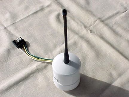
Click to zoom
Application Details
- Equipment Class
- DSC - Part 15 Security/Remote Control Transmitter
- Date of Grant
- Nov 25, 2003
- Application Purpose
- Original Equipment
- Date of Application
- Nov 25, 2003
- Equipment Note
- SET 'N TOW
- Frequency Range
- 418.00000000 - 418.00000000
- Company
- Kuntzleman Electronics, Inc.
- Country
- United States
Documents & Files
Document Text
Text extracted from the exhibit documents filed with the FCC. Open a document above to read the original.
Users Manual
Installation and use of your “SET ‘N TOW” light system “SET ‘N TOW” is made up of three units, one transmitter and two receivers, left & right. The small transmitter is attached by magnet to the towing vehicle and plugs into a four-pin flat trailer socket. The standard wire configuration is WHITE = GROUND, BROWN = TAILLIGHTS, YELLOW = LEFT TURN, GREEN = RIGHT TURN. Should you need to adapt to the plug on the transmitter make sure that configuration is followed. THE TOWING VEHICLES TAILLIGHT CIRCUIT SUPPLIES OPERATING POWER FOR THE TRANSMITTER. This means that to use the system simply turn on either the parking or headlights and the transmitter is ready. You may hot-wire the BROWN wire, so that the transmitter will be on all the time, thus eliminating the need to use the towing vehicles running lights. The receivers should be placed on the vehicle under tow in a position that the towing vehicle's driver can monitor their operation in his rear view mirrors. The lanyard rope is supplied as a safety attachment and should be used especially if the lights are attached to a vertical surface. Simply pinch it in a door, trunk, hood, or rolled up window. When placing on the vehicle, be sure that the magnetic base is clean of foreign material and is attached soundly to the vehicle under tow. The 3 position switch labeled, DAY-OFF-NIGHT, is used to turn on the receiver in either the DAY or NIGHT position. In the NIGHT position it will also turn on the taillights. The taillights are NOT operated by remote, so they must be manually turned on when using at night. The other light functions will follow what the towing vehicles lights are doing, left turn, right turn, brake, and 4 way. Each receiver has a rechargeable lead acid gel cell 12-volt battery that is recharged via an external plug. There is also an LED indicator light marked “Low Battery”. This light is designed to come on when the battery has drained to a point that it must be recharged. Each system comes with a recharging cord that can be plugged into a cigar lighter type socket to recharge the batteries. It is a good idea to keep the receivers plugged into the charging circuit while not in use, so that they will always be fully charged. Recharging can be done while the lights are in or out of service. The system will work in almost all situations; however, you may find one where they don’t. Remember the radio signals coming out of the transmitter antenna have to be received by the receiver antenna, so placement can affect operations in some cases. A longevity battery test was preformed on the system. The lights on the towing vehicle were placed in the 4 way flash mode. This put the system under the most extreme battery drain. They ran for 7 hours 40 minute before the low battery indicator came on. Optional equipment that is also available: Pump up suction cup mounts. These cups are used with the receivers when magnetic attachment to the vehicle under tow is undesirable. Note: Each system is preset with a binary address code. It is set in the transmitter and the same code is set in both receivers. All of the units are sealed to keep out moisture. So if you should, for any reason open them, make sure they are resealed when closing. INSTRUCTIONS TO THE USER. This equipment has been tested and found to comply with the limits for a class B digital device, pursuant to part 15 of the FCC Rules. These limits are designed to provide reasonable protection against harmful interference in a residential installation. This equipment generates, uses and can radiate radio frequency energy and if not installed and used in accordance with the instructions, may cause harmful interference to radio communications. However, there is no guarantee that interference will not occur in a particular installation. If this equipment does cause harmful interference to radio or television reception, which can be determined by turning the equipment off and on, user is encouraged to try to correct the interference by one or more of the following measures: Relocate the receiving antenna, increase the separation between the equipment and receiver, consult the dealer or an experienced radio/TV technician for help. Operation with non-approved equipment or unshielded cables is likely to result in interference to radio and TV reception. The user is cautioned that changes and modifications made to the equipment without approval of the manufacture could void the users authority to operate this equipment. INSTALLATION AND INSTRUCTION MANUAL SET ‘N TOW Remote Controlled Tow Lights Model KETOW1 Kuntzleman Electronics, Inc. 1660 S. Hanover St. Pottstown, PA 19465 610 326 9068
Attestation Statements
Kuntzleman Electronics, Inc. 1660 South Hanover Street, Pottstown, PA 19465 610 326 9068 - fax 610 970 907 November 12, 2003 Federal Communications Commission 7435 Oakland Mills Road Columbia, MD 21046 Gentleman This is a letter to list modifications that were added to the transmitter of “SET ‘N TOW” model KETOW1 so that it would meet compliance testing. Three resistors, in a “T” pad configuration, were added in the transmission path to the antenna. This attenuation circuit brought the level in compliance and will be incorporated during production. The resistor values and respective “R” numbers are shown on the enclosed schematic. If you have any further questions or need additional information, please feel free to give me a call at 610-326-9868. Sincerely, Richard Kuntzleman President
Cover Letter(s)
Kuntzleman Electronics, Inc. 1660 South Hanover Street, Pottstown, PA 19465 610 326 9068 - fax 610 970 907 October 27, 2003 Federal Communications Commission 7435 Oakland Mills Road Columbia, MD 21046 Gentleman This is a letter of request of confidentiality pursuant to 47 CRF 0.459, for the following “Set ‘n Tow” product: Transmitter and receivers for the operation of stop & turn signal lights for use on vehicles being towed. Under FCC Docket Number 20780 and General Docket Number 80-284 pursuant to Part 15 of FCC Rules and Regulations. Exhibit types to be held confidential are (1) schematic diagrams, (2) block diagrams, (3) and photos of any un-potted circuit cards. Removal and disassembly of such cards would destroy the product. My company has gone to considerable expense, in both time and money, in design and development of this product and would like to keep my efforts privileged due to marketing concerns. If you have any further questions or need additional information, please feel free to give me a call at 610-326-9868. Sincerely, Richard Kuntzleman President
Operational Description
Kuntzleman Electronics, Inc. 1660 South Hanover Street, Pottstown, PA 19465 610 326 9068 - fax 610 970 9078 How “SET ‘N TOW” works: The system is made up of one transmitter and two receivers. The transmitter unit has 4 wires. WHITE is –12 volts DC negative or ground, BROWN is + 12 volts DC to supply operating voltage to the transmitter. YELLOW (left) and GREEN (right) are the signal leads. When +12volts DC is applied, from a manually operated switch, to either or both it will cause the transmitter to send an operate signal to the receiver/s. When that switch is released the transmitter will deactivate in less than five seconds as defined in FCC Rule 15.231. Programmed codes set into the PIC device in the transmitter will enable it to send a start code for turn and 4 way operation, when power is removed the transmitter will then send a stop pulse to the receiver. The receiver/s are powered by their own 12 volt battery. When they receive their operate signal from the transmitter, a voltage is applied to an external lamp and it will operate in a momentary mode. In the turn and 4 way mode a PIC device in the receiver is programmed to start the flashing sequence when it receives the start pulse. Then to quit flashing when it receives the stop pulse.
Test Report
Report Number: B31031A1 FCC Part 15 Subpart B and FCC Section 15.231 Test Report Transmitter Model: Set ‘n Tow Brea Division 114 Olinda Drive Brea, CA 92823 (714) 579-0500 Agoura Division 2337 Troutdale Drive Agoura, CA 91301 (818) 597-0600 Silverado Division 19121 El Toro Road Silverado, CA 92676 (949) 589-0700 Lake Forest Division 20621 Pascal Way Lake Forest, CA 92630 (949) 587-0400 Page 1 of 15 FCC PART 15, SUBPART B and C TEST REPORT for TRANSMITTER MODEL: SET ‘N TOW Prepared for KUNTZLEMAN ELECTRONICS, INC. 1660 SOUTH HANOVER STREET POTTSTOWN, PA 19465 Prepared by:_____________________ MICHAEL CHRISTENSEN Approved by:____________________ KYLE FUJIMOTO COMPATIBLE ELECTRONICS INC. 114 OLINDA DRIVE BREA, CALIFORNIA 92823 (714) 579-0500 DATE: NOVEMBER 12, 2003 REPORT APPENDICES TOTAL BODY A B C D E PAGES 15 2 2 2 10 16 47 This report shall not be reproduced except in full, without the written approval of Compatible Electronics. Report Number: B31031A1 FCC Part 15 Subpart B and FCC Section 15.231 Test Report Transmitter Model: Set ‘n Tow Brea Division 114 Olinda Drive Brea, CA 92823 (714) 579-0500 Agoura Division 2337 Troutdale Drive Agoura, CA 91301 (818) 597-0600 Silverado Division 19121 El Toro Road Silverado, CA 92676 (949) 589-0700 Lake Forest Division 20621 Pascal Way Lake Forest, CA 92630 (949) 587-0400 Page 2 of 15 TABLE OF CONTENTS Section / Title PAGE GENERAL REPORT SUMMARY 4 SUMMARY OF TEST RESULTS 4 1. PURPOSE 5 2. ADMINISTRATIVE DATA 6 2.1 Location of Testing 6 2.2 Traceability Statement 6 2.3 Cognizant Personnel 6 2.4 Date Test Sample was Received 6 2.5 Disposition of the Test Sample 6 2.6 Abbreviations and Acronyms 6 3. APPLICABLE DOCUMENTS 7 4. DESCRIPTION OF TEST CONFIGURATION 8 4.1 Description Of Test Configuration - EMI 8 4.1.1 Cable Construction and Termination 9 5. LISTS OF EUT, ACCESSORIES AND TEST EQUIPMENT 10 5.1 EUT and Accessory List 10 5.2 EMI Test Equipment 11 6. TEST SITE DESCRIPTION 12 6.1 Test Facility Description 12 6.2 EUT Mounting, Bonding and Grounding 12 7. TEST PROCEDURES 13 7.1 Radiated Emissions (Spurious and Harmonics) Test 13 7.2 Bandwidth of the Fundamental 14 8. CONCLUSIONS 15 Report Number: B31031A1 FCC Part 15 Subpart B and FCC Section 15.231 Test Report Transmitter Model: Set ‘n Tow Brea Division 114 Olinda Drive Brea, CA 92823 (714) 579-0500 Agoura Division 2337 Troutdale Drive Agoura, CA 91301 (818) 597-0600 Silverado Division 19121 El Toro Road Silverado, CA 92676 (949) 589-0700 Lake Forest Division 20621 Pascal Way Lake Forest, CA 92630 (949) 587-0400 Page 3 of 15 LIST OF APPENDICES APPENDIX TITLE A Laboratory Recognitions B Modifications to the EUT C Additional Models Covered Under This Report D Diagrams, Charts, and Photos • Test Setup Diagrams • Radiated Emissions Photos • Antenna and Effective Gain Factors E Data Sheets LIST OF FIGURES FIGURE TITLE 1 Plot Map And Layout of Radiated Site Report Number: B31031A1 FCC Part 15 Subpart B and FCC Section 15.231 Test Report Transmitter Model: Set ‘n Tow Brea Division 114 Olinda Drive Brea, CA 92823 (714) 579-0500 Agoura Division 2337 Troutdale Drive Agoura, CA 91301 (818) 597-0600 Silverado Division 19121 El Toro Road Silverado, CA 92676 (949) 589-0700 Lake Forest Division 20621 Pascal Way Lake Forest, CA 92630 (949) 587-0400 Page 4 of 15 GENERAL REPORT SUMMARY This electromagnetic emission test report is generated by Compatible Electronics Inc., which is an independent testing and consulting firm. The test report is based on testing performed by Compatible Electronics personnel according to the measurement procedures described in the test specifications given below and in the "Test Procedures" section of this report. The measurement data and conclusions appearing herein relate only to the sample tested and this report may not be reproduced without the written permission of Compatible Electronics, unless done so in full. This report must not be used to claim product endorsement by NVLAP, NIST or any other agency of the U.S. Government. Device Tested: Transmitter Model: Set ‘n Tow S/N: N/A Product Description: See Expository Statement Modifications: The EUT was modified in order to meet the specifications. Please see list located in Appendix B. Manufacturer: Kuntzleman Electronics, Inc. 1660 South Hanover Street Pottstown, PA 19465 Test Dates: October 30 and 31, 2003 Test Specifications : EMI requirements CFR Title 47, Part 15 Subpart B; and Subpart C, Sections 15.205, 15.209 and 15.231 Test Procedure: ANSI C63.4: 2001 Test Deviations: The test procedure was not deviated from during the testing. SUMMARY OF TEST RESULTS TEST DESCRIPTION RESULTS 1 Conducted RF Emissions, 150 kHz - 30 MHz This test was not performed because the EUT operates on DC power only and cannot be plugged into the AC public mains. 2 Radiated RF Emissions, 10 kHz - 4180 MHz Complies with the Class B limits of CFR Title 47, Part 15, Subpart B; and Subpart C, sections 15.205, 15.209, and 15.231. Report Number: B31031A1 FCC Part 15 Subpart B and FCC Section 15.231 Test Report Transmitter Model: Set ‘n Tow Brea Division 114 Olinda Drive Brea, CA 92823 (714) 579-0500 Agoura Division 2337 Troutdale Drive Agoura, CA 91301 (818) 597-0600 Silverado Division 19121 El Toro Road Silverado, CA 92676 (949) 589-0700 Lake Forest Division 20621 Pascal Way Lake Forest, CA 92630 (949) 587-0400 Page 5 of 15 1. PURPOSE This document is a qualification test report based on the Electromagnetic Interference (EMI) tests performed on the Transmitter Model: Set ‘n Tow. The EMI measurements were performed according to the measurement procedure described in ANSI C63.4: 2001. The tests were performed in order to determine whether the electromagnetic emissions from the equipment under test, referred to as EUT hereafter, are within the Class B specification limits defined by CFR Title 47, Part 15, Subpart B; and Subpart C, sections 15.205, 15.209, and 15.231. Report Number: B31031A1 FCC Part 15 Subpart B and FCC Section 15.231 Test Report Transmitter Mod…
Text truncated - open the document above for the full version.
Contact Information
Applicant
Richard Kuntzleman(President)
Technical Contact
Compatible ElectronicsMichael P Christensen
[email protected]714-579-0500
114 Olinda Drive · Brea, California · United States
Test Firm
Compatible ElectronicsScott McCutchan
714-579-0500Fax: 714-579-1850
Technical Specifications
| # | Rule Parts | Frequency Range | Power Output |
|---|---|---|---|
| 1 | 15.231 | 418 MHz - 418 MHz | - |