RMM-USMS2A-AUSM Systems Transmitter
USM Systems, Ltd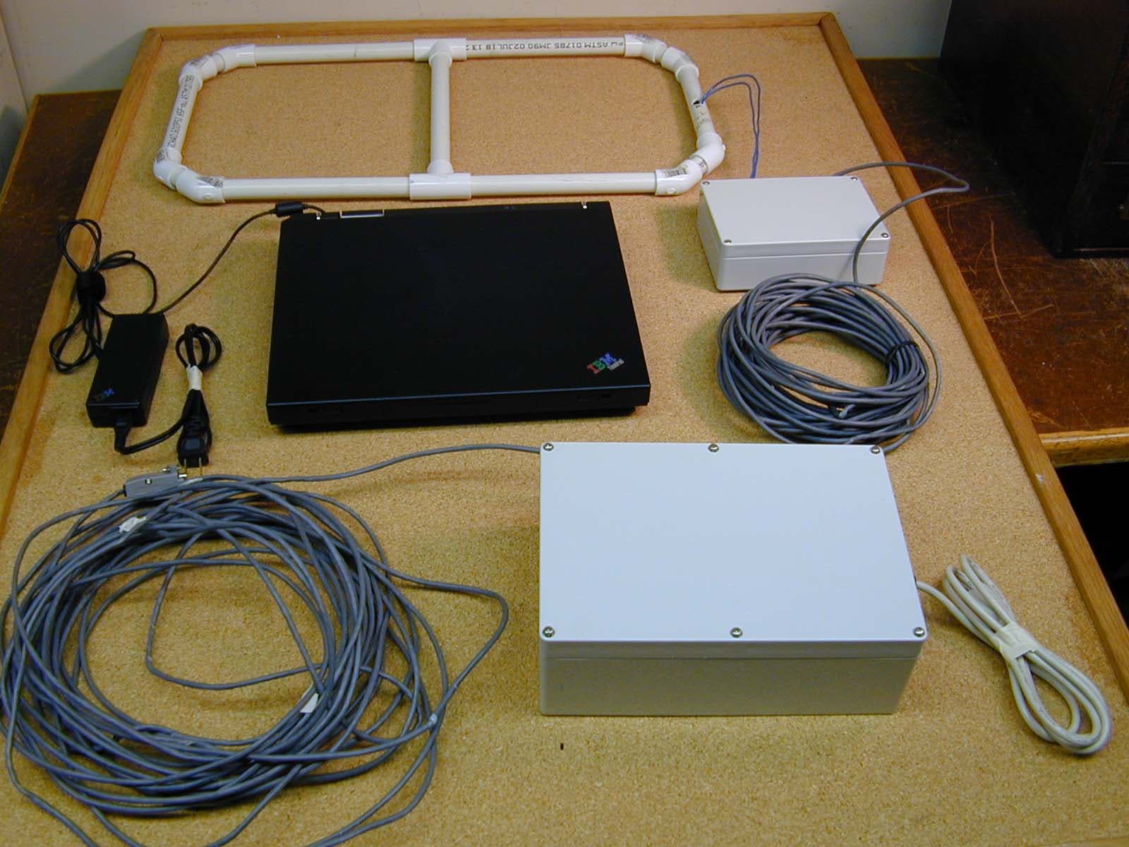
Click to zoom
Application Details
- Equipment Class
- DCD - Part 15 Low Power Transmitter Below 1705 kHz
- Date of Grant
- Mar 10, 2004
- Application Purpose
- Original Equipment
- Date of Application
- Mar 10, 2004
- Equipment Note
- USM Systems Transmitter
- Frequency Range
- 0.15400000 - 0.15400000
- Company
- USM Systems, Ltd
- Country
- United States
Documents & Files
Document Text
Text extracted from the exhibit documents filed with the FCC. Open a document above to read the original.
Users Manual
Re: Certification for USM Systems Transmitter Model: CR2A-USMS FCC ID: RMM-USMS2A-A USER'S MANUAL INFORMATION (PRELIMINARY) The User's Manual is in preparation. The following material will be contained in the manual: FCC ID: RMM-USMS2A-A This device complies with Part 15 of the FCC Rules and with RSS-210 of Industry Canada. Operation is subject to the following two conditions: (1) This device may not cause harmful interference, and (2) This device must accept any interference received, including interference that may cause undesired operation. WARNING: Changes or modifications not expressively approved by the party responsible for compliance could void the user's authority to operate the equipment.
Attestation Statements
Re: Certification for USM Systems Transmitter Model: CR2A-USMS FCC ID: RMM-USMS2A-A POWER OF ATTORNEY A letter granting Valdis V. Liepa the Power of Attorney is on file and can be provided when so requested. Re: Certification for USM Systems Transmitter Model: CR2A-USMS FCC ID: RMM-USMS2A-A REQUEST FOR CONFIDENTIALITY Pursuant to 47 CRF 0.459, USM Systems requests that a part of the subject application be held confidential. This comprises Exhibits (5) Schematics (10) Parts List (Part of Exhibit only) USM Systems has spent substantial effort in developing this product and it is one of the first of its kind in industry. Having the subject information easily available to "competition" would negate the advantage they have achieved by developing this product. Not protecting the details of the design will result in financial hardship. If there are any questions regarding this request, please contact me at the above address or call 734-483-4211, fax 734-647-2106 or e-mail [email protected]. Sincerely, Valdis V. Liepa Research Scientist University of Michigan January 31, 2004 Re: Certification for USM Systems Transmitter Model: CR2A-USMS FCC ID: RMM-USMS2A-A STATEMENT OF MODIFICATIONS There were no modifications made to the DUT by this test laboratory. (Also see Section 3.1 of the attached Test Report). _____________________ Valdis V. Liepa Research Scientist Re: Certification for USM Systems Transmitter Model: CR2A-USMS FCC ID: RMM-USMS2A-A GENERAL PRODUCT INFORMATION The device, for which certification is pursued, has been designed by: USM Systems, Ltd Suite 200, 2998 Eleven Mile Road Berkley, MI 48072 Chet Przygoda Tel: (800) 496-7603 Fax: (800) 496-7607 It will be manufactured by: USM Systems, Ltd Suite 200, 2998 Eleven Mile Road Berkley, MI 48072 Chet Przygoda Tel: (800) 496-7603 Fax: (800) 496-7607
Block Diagram
Loop Antenna Tuning Capacitor Block Main Control Unit IC: 8.0 MHz XTAL: 4.9152 MHz 25 ft. RS232 Unshielded 25 ft. multi- conductor wire Unshielded 2 ft 2 – 24 ft 2 Turns (max): 3 120 VAC
Cover Letter(s)
January 31, 2004 American Telecommunications Certification Body, Inc. 6731 Whittier Avenue Suite C110 McLean, VA 22101 RE: Certification Application FCC ID: RMM-USMS2A-A Please find enclosed application materials for certification of USM Systems CR2A- USMS Transmitter. Note: 1) portions of this submittal are filed Confidential 2) a list of the modifications made is provided in Attestations. We are requesting that the DUT be granted for a range of antennas, up to a total effective area of 72 ft 2 (24 ft 2 x 3 Turns). If there are any questions regarding the application or testing performed, please contact me at the above address or call 734-483-4211, fax 734-647-2106, or e-mail [email protected]. Sincerely, Valdis V. Liepa Research Scientist
Cover Letter(s)
January 31, 2004 Federal Communications Commission Equipment Approval Services P.O. Box 358315 Pittsburgh, PA 15251-5315 Re: Certification for USM Systems Transmitter Model: CR2A-USMS FCC ID: RMM-USMS2A-A Please find enclosed application materials for certification of USM Systems CR2A- USMS Transmitter. We tested it and found it to comply with FCC Part 15. If there are any questions regarding the application or testing performed, please contact me at the above address or call 734-483-4211, fax 734-647-2106, or e-mail [email protected]. Sincerely, Valdis V. Liepa Research Scientist
Operational Description
1.2. The CR2A reader A Cryptag Census reader identifies tags (sometimes referred to as tokens or cards) using low frequency radio signals. CR2A transmits to the tag at 153 kHz and detects the tag’s response which is at 115kHz. CR2A uses frequencies which are permitted in USA. The CR2A reader is a cost effective reader for longer range applications that do not require the full capabilities of CR1A readers. The CR2A can only be used with a single antenna loop (internal or external). With the external antenna loop fitted, the reading range depends on the size and shape of the loop as well as on the type of tag. The CR2A reader is configurable, and this is normally done in the factory. Configuration controls the output format, timings etc. Identec Ltd CR2A Reader Installation Sheet TXATXBSCN 0VHold (Card Present)Wiegand D0 (Clock)Wiegand D1 (Data)Green LED 0VScreenV+ (8V to 28V)Serial outSerial in Range Max Low Red Amber Green Noise LED Data LED Te s t Area The printed circuit board of the CR2 reader The CR2 reader can be used as a self-contained reader, using the internal antenna loop, or it can be used with an external antenna loop. Installation The reading range of the CR2 reader is approximately 1.5 metres with the internal loop, and 3 metres with an external loop 2 metres square. With such ranges it is essential to carry out a Site Survey using an MS3A Site Survey Meter to ensure that the site is free from interference. (Since the range is similar to the CR1 reader, you are advised to read the CR1 manual – much of it also applies to this reader.) The reader is mounted using the 3 holes in the base. If the reader is to be used in an exposed position the cable entry hole should be protected. (If a lot of condensation is expected, drill a drainage hole at the bottom of the reader.) All connections to the reader should use screened cables. See below for how to connect the screens. , with the screen connected to the Screen terminal. The screens should be earthed at the controller end. (If this causes problems, connect a 1nF capacitor between the screen and earth at the controller end.) Connections 0V Reference for supplies and data connections Screen All cables must be screened. See below for other details on connections. V+ Positive power supply (8 to 28V at typically 80mA) (Range drops below 13V, falling to 80% at 8V) Serial Out Pseudo-RS232 data output (9600 baud, 8 data, 1 stop bit, no parity) Serial In Only used when configuring readers 0V Extra 0V connection for data cables Hold Normally unconnected. Connect to 0V to pause Wiegand reporting. Wiegand D0 Wiegand format output D0 line. (5V with low going pulses) Wiegand D1 Wiegand format output D1 line. Green LED Connect to 0V to turn the green LED on. For Clock/Data output readers, the Hold and Wiegand lines are used as shown in the figure. Maximum cable lengths Wiegand 100 metres Serial out 10 metres (to RS232 input) Coil connections (for use with external antenna loops) Screen The cable to the coil must be screened, with the screen connected here. TXA/TXB Coil connections. Connect to the coil and tuning capacitor If an external loop is used, disconnect the internal coil. The external loop should be tuned with the correct type of capacitor, as close as possible to the loop. The capacitance required can be measured using MS3A Site Survey Meter (or adjust for minimum current consumption into the reader). Screen Connections Screened cables should be used both for the antenna cable and the power/data cable(s). In addition the screen of the power cable must be connected at one end. It is preferred that the screen is connected to the 0V line at the reader and left unconnected at the other end. If the other end of the screen must be connected, then connect a 1nF capacitor between screen connection and 0V. Screened cable, and correct connection of the cable screen, is necessary for good performance. Operation The reading range can be reduced (to 50-60%) by putting the Range link to the bottom. For full range put the link to the top. (Omitting the link is not recommended. It gives an intermediate range, but tags will cease to read very close to the reader.) When a tag is being read the amber LED flashes. The Noise LED flashes if a tag is present, or if there is interference that may affect reading range. The Data LED flashes momentarily when a tag is reported. All tags are reported on both the Wiegand and RS232 outputs. (Unless the tag does not belong to the same site as the reader.) If an external coil is fitted, tags will read within a few centimetres of the Test Area near the coil connections. Identec Ltd February 2002
Test Report
The University of Michigan Radiation Laboratory 3228 EECS Building Ann Arbor, MI 48109-2122 Tel: (734) 764-0500 Measured Radio Frequency Emissions From USM Systems Transmitter Model: CR2A-USMS Report No. 415031-196 January 31, 2004 Copyright © 2004 For: USM Systems, Ltd Suite 200, 2998 Eleven Mile Road Berkley, MI 48072 Contact: Chet Przygoda Tel: (800) 496-7603 Fax: (800) 496-7607 Tests supervised by: Measurements made by: Fred. P. Vong Report approved by: _____________________ Joseph D. Brunett Valdis V. Liepa Ryan Ringler Research Scientist Summary Tests for compliance with FCC Regulations, Part 15, Subpart C, and for compliance with Industry Canada RSS-210, were performed on USM Systems, Ltd transmitter, model CR2A-USMS. This device is subject to Rules and Regulations as a transmitter. In testing completed January 28, 2004, the device tested in the worst case met the allowed specifications for transmitter radiated emissions by 19.8 dB (see p. 7); digital emissions, Class A, were met by 2.2 dB (see p. 7); FCC/CISPR Class A conducted were met by 2.8 dB (see p. 7). 2 1. Introduction USM Systems model CR2A-USMS was tested for compliance with FCC Regulations, Part 15, adopted under Docket 87-389, April 18, 1989, and with Industry Canada RSS-210, Issue 5, November, 2001. The tests were performed at the University of Michigan Radiation Laboratory Willow Run Test Range following the procedures described in ANSI C63.4-1992 "Methods of Measurement of Radio-Noise Emissions from Low-Voltage Electrical and Electronic Equipment in the Range of 9 kHz to 40 GHz". The Site description and attenuation characteristics of the Open Site facility are on file with FCC Laboratory, Columbia, Maryland (FCC Reg. No: 91050) and with Industry Canada, Ottawa, ON (File Ref. No: IC 2057). 2. Test Procedures and Equipment Used The pertinent test equipment commonly used in our facility for measurements is listed in Table 2.1 below. The middle column identifies the specific equipment used in these tests. Table 2.1 Test Equipment. Test Instrument Eqpt. Used Manufacturer/Model Spectrum Analyzer (0.1-1500 MHz) Hewlett-Packard, 182T/8558B Spectrum Analyzer (9kHz-22GHz) X Hewlett-Packard 8593A SN: 3107A01358 Spectrum Analyzer (9kHz-26GHz) X Hewlett-Packard 8593E, SN: 3412A01131 Spectrum Analyzer (9kHz-26GHz) Hewlett-Packard 8563E, SN: 3310A01174 Spectrum Analyzer (9kHz-40GHz) Hewlett-Packard 8564E, SN: 3745A01031 Power Meter Hewlett-Packard, 432A Power Meter Anritsu, ML4803A/MP Harmonic Mixer (26-40 GHz) Hewlett-Packard 11970A, SN: 3003A08327 Harmonic Mixer (40-60 GHz) Hewlett-Packard 11970U, SN: 2332A00500 Harmonic Mixer (75-110 GHz) Hewlett-Packard 11970W, SN: 2521A00179 Harmonic Mixer (140-220 GHz) Pacific Millimeter Prod., GMA, SN: 26 S-Band Std. Gain Horn S/A, Model SGH-2.6 C-Band Std. Gain Horn University of Michigan, NRL design XN-Band Std. Gain Horn University of Michigan, NRL design X-Band Std. Gain Horn S/A, Model 12-8.2 X-band horn (8.2- 12.4 GHz) Narda 640 X-band horn (8.2- 12.4 GHz) Scientific Atlanta , 12-8.2, SN: 730 K-band horn (18-26.5 GHz) FXR, Inc., K638KF Ka-band horn (26.5-40 GHz) FXR, Inc., U638A U-band horn (40-60 GHz) Custom Microwave, HO19 W-band horn(75-110 GHz) Custom Microwave, HO10 G-band horn (140-220 GHz) Custom Microwave, HO5R Bicone Antenna (30-250 MHz) X University of Michigan, RLBC-1 Bicone Antenna (200-1000 MHz) X University of Michigan, RLBC-2 Dipole Antenna Set (30-1000 MHz) X University of Michigan, RLDP-1,-2,-3 Dipole Antenna Set (30-1000 MHz) EMCO 2131C, SN: 992 Active Rod Antenna (30 Hz-50 MHz) EMCO 3301B, SN: 3223 Active Loop Antenna (30 Hz-50 MHz) X EMCO 6502, SN:2855 Ridge-horn Antenna (300-5000 MHz) X University of Michigan Amplifier (5-1000 MHz) X Avantek, A11-1, A25-1S Amplifier (5-4500 MHz) X Avantek Amplifier (4.5-13 GHz) Avantek, AFT-12665 Amplifier (6-16 GHz) Trek Amplifier (16-26 GHz) Avantek LISN Box University of Michigan Signal Generator Hewlett-Packard 8657B 3 3. Configurations and Identification of Device Under Test The DUT is an industrial use RFID system. This system consists of a 154 kHz Tx / 115 kHz Rx module with varying LF loop antenna sizes. (An assortment of antenna sizes have been tested, limited to a maximum loop size of 24 sq. ft. with 3 turns.) A active transponder (FCC ID: JHD-CEN1,2,3,4) is used to communicate with the system. The loop antenna is connected to a series capacitor jumper box for resonating the antenna at the Tx operating frequency (154 kHz). From the capacitor box, 25 ft of twisted pair multi-conductor wire runs to the control box. Within the control box is the AC power supply, LF driver circuitry, and RS-232 interface. Another 25 ft. of RS-232 cable is used to connect the control box to a Laptop computer that receives id numbers from a transponder, as detected by the DUT. The DUT was designed and manufactured by USM Systems, Ltd, Suite 200, 2998 Eleven Mile Road, Berkley, MI 48072. It is identified as: USM Systems, Ltd Transmitter Model: CR2A-USMS FCC ID: RMM-USMS2A-A This test report demonstrates that this device is compliant with the FCC rules and regulations as a LF transmitter for all loop antennas with a minimum effective area of 2 ft 2 (2 ft 2 x 1 turn) and a maximum effective area of 72 ft 2 (24 ft 2 . x 3 turns). 3.1 EMI Relevant Modifications No EMI Relevant Modifications were performed by this test laboratory. 4. Emission Limits 4.1 Radiated Emission Limits The DUT tested falls under the category of an Intentional Radiators and the Digital Devices, subject to Subpart C, Section 15.209; and Subpart B, Section 15.109 (transmitter generated signals excluded); and Subpart A, Section 15.33. The applicable testing frequencies with corresponding emission limits are given in Tables 4.1 and 4.2 below. As a digital device, it is exempt. Table 4.1. Radiated Emission Limits (FCC: 15.205, 15.35; IC: RSS-210 (6.2.2(r), 6.3)). (Transmitter) Frequency (MHz) Fundamental and Spurious* (μV/m) 0.009-0.490 0.490-1.705 2400/F(kHz), 300m 24,000/F(kHz…
Text truncated - open the document above for the full version.
Test Setup Photos
DUT on OATS (small loop 1 ft. x 2 ft.) DUT on OATS close-up (small loop 1 ft. x 2 ft.) DUT on OATS (medium loop 2 ft. x 3 ft.) DUT on OATS close-up ( medium loop 2 ft. x 3 ft.) DUT on OATS (large loop 4 ft. x 6 ft.) D UT on OATS close-up (large loop 4 ft. x 6 ft.) Conducted Emissions Setup
Contact Information
Applicant
Chet Przygoda(President)
Technical Contact
University of Michigan/EECSValdis V Liepa
[email protected]734-483-4211
1301 Beal Avenue · Ann Arbor, Michigan · United States
Test Firm
University of MichiganValdis Liepa
Technical Specifications
| # | Rule Parts | Frequency Range | Power Output |
|---|---|---|---|
| 1 | 15C | 0.154 MHz - 0.154 MHz | - |