RN8TIPS001Tire Pressure Transmitter Activator
SPX Corporation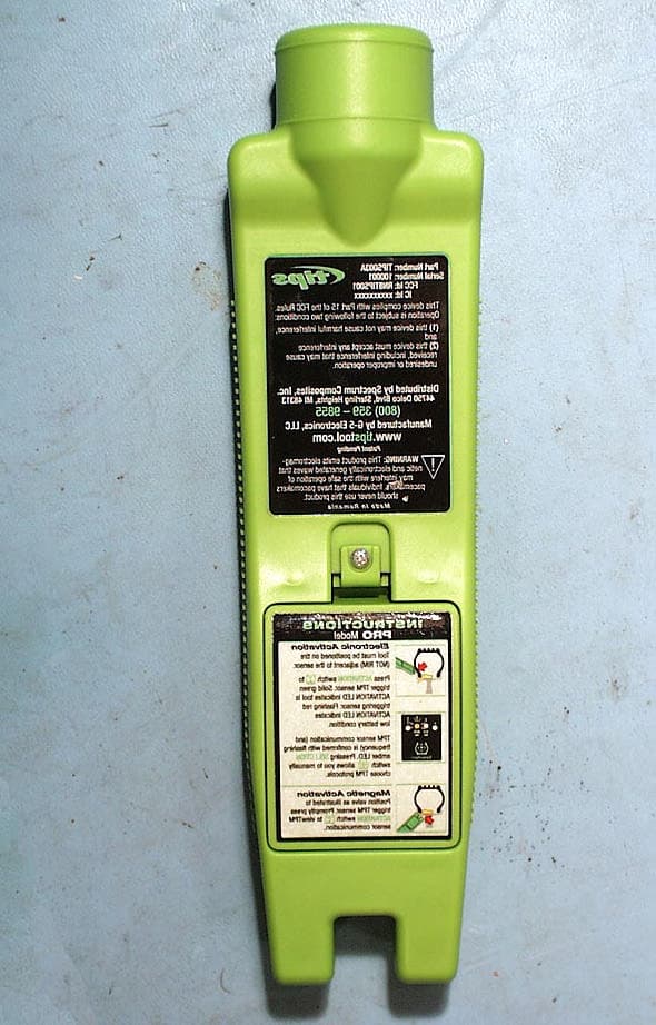
Click to zoom
Application Details
- Equipment Class
- DXT - Part 15 Low Power Transceiver, Rx Verified
- Date of Grant
- Nov 28, 2004
- Application Purpose
- Original Equipment
- Date of Application
- Nov 28, 2004
- Equipment Note
- Tire Pressure Transmitter Activator
- Frequency Range
- 0.12500000 - 0.12500000
- Company
- SPX Corporation
- Country
- United States
Documents & Files
Document Text
Text extracted from the exhibit documents filed with the FCC. Open a document above to read the original.
Users Manual
User Guide Pro Model TIPS003 1104 Manufactured under US Patent # xxxxxxxxxx, International Patents Pending 2 Table of Contents IMPORTANT: In order to assure that you receive product support services, technical updates and information pertaining to upgrades, please take a few minutes to properly register your T.I.P.S. Tool. Please either complete the warranty registration card shipped with your tool or register online at www.tipstool.com. Page Important Safety Information X Introduction X Operating Instructions T.I.P.S. Pro Tool Overview X Using the T.I.P.S. Tool X Low Battery Indication X Battery Replacement X Software Upgrades X Cleaning X Storage X Trouble Shooting X Customer Support X Specifications X Limited Warranty X 3 IMPORTANT SAFETY INSTRUCTIONS Do not discard. Retain for future reference CAUTION: TO REDUCE THE RISK OF ELECTRIC SHOCK, DO NOT REMOVE COVER (OR BACK) FOR SERVICE. NO SERVICABLE PARTS INSIDE. REFER SERVICING TO MANUFACTURER OR AUTHORIZED SERVICE CE NTER. The exclamation point with an equilateral triangle is intended to alert the user to important operating and maintenance (servicing) instructions in the literature accompanying the appliance The lightning flash with arrowhead symbol within an equilateral triangle is intended to alert the user to uninsulated "dangerous voltage" within the product enclosure that may be of sufficient ma gnitude to constitute a risk of electric shock. WARNING: This product emits magnetic and ectromagnetic waves that may interfere with the safe operation of pacemakers. Individuals that have pacemakers should never use this product. FCC Notice: Id RN8TIPS001 This tool complies with part 15 of the FCC Rules. Operation is subject to the following two conditions: 1) This tool may not cause harmful interference, and 2) This tool must accept any interference received, including interference that may cause undesired or improper operation. This equipment is an intentional transmitter. Any changes or modifications not approved by the manufacturer could void the user's authority to operate the equipment. WARNING: Risk of Explosion. This equipment has internal arcing or sparking parts that should not be exposed to flammable vapors. This equipment should be used at least 460 mm (18 inches) above the floor. Notice Information in this document is subject to change without notice. G-5 Electronics, LLC may have patents, copyrights, trademarks, or other intellectual property rights covering subject matter in this document. Information in this document may not be reproduced without the written consent of G-5 Electronics, LLC. Except as expressly provided in any license agreement, the furnishing of this document does not provide the user any license to these patents, trademarks, copyrights, or other intellectual property. Patent Pending 4 CAUTION READ THESE INSTRUCTIONS BEFORE USING Your Tire Inflation Positioning Switch (T.I.P.S.) Tool has been designed to be durable, safe, and reliable when properly used. All T.I.P.S. Tools are intended to be used only by qualified and trained personnel in a Laboratory or a light industrial repair shop environment. This equipment is an intentional transmitter. Any changes of modifications not approved by the manufacturer could void the user's authority to operate the equipment. Please read all instructions below before using. Always follow these safety instructions. If you have any question that pertains to the safe or reliable use of this tool, please call (800) 359-9855 between 9:00 am - 4:30 p.m. Eastern Time. If calling from outside the USA please call 01-586- 726-5525 or email your question to [email protected]. 1. Read all instructions. All warnings on the tool and in this manual should be adhered to. All operating and use instructions should be followed. 2. Retain Instructions The safety and operating instructions should be retained for future use. 3. Heed Warnings All warnings on the tool and in the operating instructions should be adhered to. 4. Follow Instructions All operating and use instructions should be followed. 5. Cleaning Clean with a soft dry cloth, or if necessary, a soft damp cloth. Do not use any harsh chemical solvents such as acetone, thinner, alcohol, etc as this may damage the plastic surface. 6. Water & Moisture Do not use this tool where contact or immersion in water is a possibility. Never spill liquid of any kind onto tool. 7. Storage Do not use or store the tool in an area where it exposed to direct sunlight or excessive moisture, i.e. outdoors, near wash systems, etc. 8. Use To reduce the risk of fire, do not operate the tool in the vacinity of open containers or flammable liquids. Do not use where the potential for explosive gas or vapors exists. Keep the tool away from heat generating sources. Do not operate the tool with the battery cover removed. 9. Battery Replacement Replace all six batteries promptly after receiving the low battery indication (RED ACTIVATION LED). Only size AA Alkaline type batteries should be used. Do not use rechargeable batteries. When disposing batteries please comply with all local, state, or country guidelines. 10. Servicing Do not attempt to service this tool yourself, as opening or removing covers (with the exception of the battery cover) may expose you to dangerous voltage or other hazards. Refer all servicing to authorized service personnel. Do not use this tool if it appears damaged or is not operating properly. 5 Introduction Tire Pressure Monitoring Systems, commonly known as TPM systems, will soon be installed on most of the automobiles manufactured in the world. Most of these systems use a “direct” approach which incorporates the use of wheel based transmitters or sensors (typically incorporated into the valve stem) which report tire pressure (in addition to the sensor ID) to the engine control module (ECM) or some specific controller module on the vehicle. In order to conserve batter life, these sensors are designed to transmit information to t…
Text truncated - open the document above for the full version.
Cover Letter(s)
AHD EMC Lab, 92723 M152, Dowagiac, MI 49047, (616) 424-7014 491952.DOC Cover / Confidentiality Request Letter: Page 1 of 2 NVLAP ACCREDITED NARTE Certified Engineer Professional Engineer ELITE Electronic Engineering TCB Services 1516 Centre Circle Downers Grove, IL 60515-1082 Re: ELITE Quote #EEE-Q21194TCB Application for Certification of G5 Electronics Tire Pressure Transmitter Activator under 47CFR 15.209. For G5 Electronics Transceiver TIPS family, FCC ID: RN8TIPS001 Gentlemen: On behalf of the applicant, G5 Electronics, LLC, please find attached the submittal materials for certification of the “Tire Pressure Transmitter Activator”, models ‘TIPS Basic Analog’, ‘TIPS Plus Analog’, ‘TIPS Basic’, ‘TIPS Plus’, ‘TIPS PRO’, and ‘TIPS Elite’. . The product is a low power transceiver used to activate the tire pressure monitors/sensors located in the vehicle tire. The product transmits a magnetic field at 125KHz and receives response signals at 315MHz and 434MHz. The unit evaluated, model TIPS PRO is at the high end of a product family consisting of ‘TIPS Basic Analog’, ‘TIPS Plus Analog’, ‘TIPS Basic’, ‘TIPS Plus’, ‘TIPS PRO’,and ‘TIPS Elite’. This submittal requests to have all the models included in the approval. The complete List of the Exhibits in this submittal package appears on Page 2 of this cover letter. G5 Electronics has invested considerable resources into developing this product. Pursuant to 47CRF 0.459, G5 Electronics requests that the Circuit Block Diagrams, Theory/Description of Operation, and Schematics be held confidential. The Federal Communications Commission will be notified, in writing, of any changes in the software/programming of the device that could affect the device’s RF characteristics. Your prompt consideration of this application for product certification will be greatly appreciated. Should you have any questions regarding the content of this report, kindly contact me. Sincerely, Ted Chaffee, Technical Lab Manager Narte Certified Engineer, #EMC-002025-NE tel/fax: 269. 424.7014 email: [email protected], or [email protected] Test report #0400719F FCC 15.209 for TIPS PRO FCC ID: RN8TIPS001 Tested October 15, 2004 AHD EMC Lab, 92723 M152, Dowagiac, MI 49047, (616) 424-7014 491952.DOC Cover / Confidentiality Request Letter: Page 2 of 2 Table of Contents Cover Letter / Table of Contents Total Pages 2 EXHIBIT A: ID Label / Location [2.925,2.926,2.1033(b2,7),15.19(a3)] Label description EXA_Label.doc Total Pages 1 EXHIBIT B: Description of Product [2.1033(b6)] EXB_desc.doc Total Pages 1 Circuit Block Diagram [2.1033(b5)] EXB_BlockDiagram Total Pages 1 Description of Operation [2.1033(b4)] EXB_TechnicalDescription.doc Total Pages 10 Schematic [2.1033(b5)] EXB_TIPSProSchematic.pdf Total Pages 1 Receiver IC data sheet EXB_rectICdata.pdf Total Pages 9 EXHIBIT C: Product photos Total Pages 6 Exterior views [2.1033(b7)] Two photos EXC_EUTbtm.jpg, EXC_EUTtop.jpg : Interior & Printed Circuit Boards [2.1033(b7)] Three photos EXC_EUTin.jpg, EXC_PCBtop.jpg, EXC_PCBbtm.jpg, , EXHIBIT D: User’s Manual EXD_draftManual.doc Total Pages 10 EXHIBIT E: Setup photos [2.1033(b8)] Four photos Total Pages 5 EXE_pretest.jpg, EXE_radflat.jpg, EXE_radside.jpg, EXE_radend.jpg Report of Measurements [2.1033(b6)] Total Pages 12 Table of Contents Page 2 Manufacturer/Applicant [2.1033(b1)] Page 4 Measurement/Test Facility & Equipment Page 4 Configuration/Setup [2.1033(b8)] Page 5 Test Standards / Methods Used [2.1033(b6)] Page 7 Test Methodology [2.1033(b6)] Page 7 Test Data [2.1033(b6)] Summary of Results Page 6 Radiated Field Strength [15.231(b)] Page 10 Occupied Bandwidth Page 12 Misc. EXHIBIT: RF Exposure Information [2.1093(c)] Total Pages 1
ID Label/Location Info
Test report #0400719F FCC 15.231 for TIPS PRO FCC ID: RN8TIPS001 Tested October 15, 2004 AHD EMC Lab, 92723 M152, Dowagiac, MI 49047, (269) 424-7014 491942.DOC Exhibit A: Page 1 of 2 EXHIBIT A: EQUIPMENT LABEL [2.925, 2.926, 2.1033(B2,7), 15.19(A3)] Drawing of label The FCC Identifier assigned to the EUT is FCC ID: RN8TIPS001. The Industry Canada Identifier assigned to the EUT is IC: 5494A-TIPS001. Theses identifiers will be imprinted on a 1 15/16” x 2 3/4” label with a polycarbonate overlay and permanently attached to the plastic housing using 3M adhesive 468. The identification information placed on the label is: (in highlighted area of drawing). PartNumber: TIPS003A Serial Number: xxxxxx FCC ID: RN8TIPS001 IC: 5494A-TIPS001 The following statement is also on the label. “This device complies with FCC rules Part 15. Operation is subject to the following two conditions: (1) this device may not cause harmful interference, and (2) this device must accept any interference that may be received including interference that may cause undesired operation. ID Number LOCATION The label will be placed on the exterior of the housing using a 3M adhesive that will permanently affix the label.
RF Exposure Info
Test report #0400719F FCC 15.209 for TIPS PRO FCC ID: RN8TIPS001 Tested October 15, 2004 AHD EMC Lab, 92723 M152, Dowagiac, MI 49047, (269) 424-7014 491951.DOC Misc. EXHIBIT: Page 1 of 1 MISC. EXHIBIT: RF EXPOSURE INFORMATION [2.1093(C)] The manufacturer and applicant: G5 ELECTRONICS, LLC 2727 Apache Trail Wixom, MI 48393 Product: Tire Pressure Transmitter Activator Model: TIPS PRO Applicable Rules: 47CFR Part 15.209 Pursuant to 47CFR Part 1.1307(b), 47CFR Part 2.1091(c), and 47CFR Part 2.1093(c) this transmitting device, compliant to 47CFR Part 15.209, is categorically excluded from evaluation regarding the Maximum Permissible Exposure of RF energy.
Test Report
Test report #0400719F FCC 15.209 for TIPS PRO FCC ID: RN8TIPS001 Tested October 15, 2004 AHD EMC Lab, 92723 M152, Dowagiac, MI 49047, (269) 424-7014 491950.DOC EXHIBIT E: Page 1 of 12 EXHIBIT E: REPORT OF MEASUREMENTS [2.1033(B6)] Test Report for FCC ID: RN8TIPS001 FCC Part 2.1031, Part 15 Subpart C(15.209) Report #0400719F Issued 11/01/04 MODEL TIPS PRO Prepared for: Mr. Ernie Pacsai G5 Electronics, LLC 2727 Apache Trail. Wixom, MI 48393 Test Date(s): September 7,24, October 15, 2004 data recorded by witnessed by Ted Chaffee, NCE This report prepared by: Ted Chaffee, NCE Technical Manager/Test Engineer, AHD Test report #0400719F FCC 15.209 for TIPS PRO FCC ID: RN8TIPS001 Tested October 15, 2004 AHD EMC Lab, 92723 M152, Dowagiac, MI 49047, (269) 424-7014 491950.DOC EXHIBIT E: Page 2 of 12 TABLE OF CONTENTS EXHIBIT E: Report of Measurements [2.1033(b6)] .....................................................................................1 TABLE OF CONTENTS.........................................................................................................................2 Statements Concerning this Report.......................................................................................................3 Manufacturer/Applicant [2.1033(b1)] ....................................................................................................4 Measurement/Test Site Facility & Equipment........................................................................................4 Test Site [2.948, 2.1033(b6)] ......................................................................................................4 Measurement Equipment Used [2.947(d), 15.31(b)] ....................................................................4 Tested Configuration /Setup: [2.1033(b8)] ............................................................................................5 Support Equipment & Cabling .......................................................................................................5 Setup Diagram ...............................................................................................................................5 Summary of Results: .............................................................................................................................6 Changes made to achieve compliance..........................................................................................6 Standards Applied to Test: [2.1033(b6)]................................................................................................7 Test Methodology: [2.1033(b6)].............................................................................................................7 Variance from Test Procedure.......................................................................................................7 Radiated.........................................................................................................................................8 FORMULAS AND SAMPLE CALCULATIONS: .............................................................................9 Test Data [2.1033(b6)].........................................................................................................................10 Radiated Field Strength Measurements: [15.209].......................................................................10 20dB Occupied Bandwidth (ANSI C63.4, Annex I.6)...................................................................12 Test report #0400719F FCC 15.209 for TIPS PRO FCC ID: RN8TIPS001 Tested October 15, 2004 AHD EMC Lab, 92723 M152, Dowagiac, MI 49047, (269) 424-7014 491950.DOC EXHIBIT E: Page 3 of 12 Statements Concerning this Report NVLAP Accreditation: NVLAP Lab Code 200129-0 The scope of AHD accreditation is the test methods of: IEC/CISPR 22: Limits and methods measurement of radio disturbance characteristics of information technology equipment. FCC Method – 47 CFT Part 15: Digital Devices. AS/NZS 3548: Electromagnetic Interference – Limits and Methods of Measurement of Information Technology Equipment. IEC61000-4-2 and Amend.1: ElectroStatic Discharge Immunity IEC61000-4-5: Surge Immunity Test Data: This test report contains data included in the scope of NVLAP accreditation. Subcontracted Testing: This report does not contain data produced under subcontract. Test Traceability: The calibration of all measuring and test equipment and the measured data using this equipment are traceable to the National Institute for Standards and Technology (NIST). Limitations on results: The test results contained in this report relate only to the Item(s) tested. Any electrical or mechanical modification made to the test item subsequent to the test date shall invalidate the data presented in this report. Any electrical or mechanical modification made to the test item subsequent to this test date shall require an evaluation to verify continued compliance. Limitations on copying: This report shall not be reproduced, except in full, without the written approval of AHD. Limitations of the report: This report shall not be used to claim product endorsement by NVLAP, FCC, or any agency of the US Government. Statement of Test Results Uncertainty: Following the guidelines of NAMAS publication NIS81 and NIST Technical Note 1297, the Measurement Uncertainty at a 95% confidence level is determined to be: ± 1.4 dB Test report #0400719F FCC 15.209 for TIPS PRO FCC ID: RN8TIPS001 Tested October 15, 2004 AHD EMC Lab, 92723 M152, Dowagiac, MI 49047, (269) 424-7014 491950.DOC EXHIBIT E: Page 4 of 12 Manufacturer/Applicant [2.1033(b1)] The manufacturer and applicant: G5 Electronics, LLC 2727 Apache Trail. Wixom, MI 48393 Measurement/Test Site Facility & Equipment Test Site [2.948, 2.1033(b6)] The AHD test facility is centered on 9 acres of rural property near Sister Lakes, Michigan. The mailing address is 92723 M-152, Dowagiac, Michigan 49047. This test facility is NVLAP accredited (LabCode 200129-0). It has been …
Text truncated - open the document above for the full version.
Contact Information
Applicant
Bill W Wittliff(Project Engineer)
Non-Technical Contact
AHDTed N Chaffee
[email protected]269-424-7014
Test Firm
AHD (Amber Helm Development, L.C.)Gordon Helm
Technical Specifications
| # | Rule Parts | Frequency Range | Power Output |
|---|---|---|---|
| 1 | 15C | 0.125 MHz - 0.125 MHz | - |