RNP70939000Radio Remote Control
Zieher KG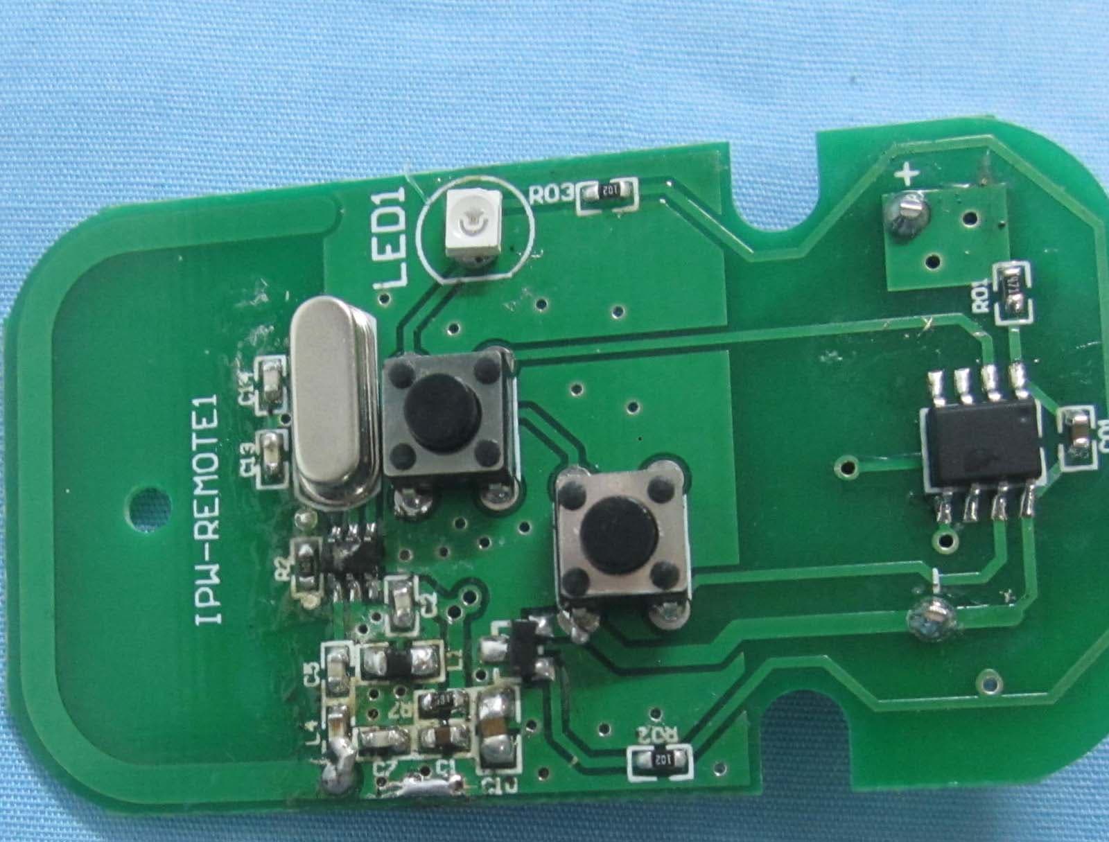
Click to zoom
Application Details
- Equipment Class
- DSC - Part 15 Security/Remote Control Transmitter
- Date of Grant
- Mar 06, 2013
- Application Purpose
- Original Equipment
- Date of Application
- Mar 06, 2013
- Equipment Note
- Radio Remote Control
- Frequency Range
- 433.83810000 - 433.83810000
- Company
- Zieher KG
- Country
- Germany
Documents & Files
Document Text
Text extracted from the exhibit documents filed with the FCC. Open a document above to read the original.
Users Manual
Rechargeable LED-light with radio remote control: Items: 8150 rechargeable LED-light 8151 radio remote control for item 8150 The new and more compact rechargeable LED-lights can be controlled with a remote control. The lighting colour for the complete buffet can be changed by pressing only one button. So Zieher‘s „Lightning Buffet“ becomes still more flexible and remains independent from any power supply and spatial requirement! The system offers the following advantages: - buffet set-up on the outside, next to the pool and in the center of a room - no troublesome cables and controllers that might get into the guests‘ or the personnel‘s way - remote control item 8151 (please order separately) controls up to 20 LED-lights at the same time / range up to 15 m - 7 fixed colours and 3 special programs manageable via remote control (white, green, red, blue, yellow, violet, turquoise, flickering-candle-effect, colour change, colour gradient) - 3 different brightness-settings selectable (100% - 70% - 50%, only adjustable directly at the LED-light) - fixedly integrated high-end batteries guarantee a running-time up to 20 hrs, depending on the brightness-setting - LED-light item 8150 is waterproof up to 1 m - charging base can be mounted on a wall and features a space-saving cable spool user manual for items 8151 1. Necessary accessories (please order separately): 8151: radio remote control, with CE and FCC labelling, incl. battery CR2032 (3V 10mA) 2. Start-up and functions: 3a) Item 8150 LED-light: Unpacking: The LED-light item 8150 will be delivered precharged and can be used immediately after unpacking. Due to previous storing time and a certain amount of self discharge of the battery, we still advise to charge the LED-light on a charging base item 8152... before first use. The blue charging control light shows the current charging status, once the light goes out the battery is fully charged. Switch on: To switch on the LED-light, please press one of the two buttons on the bottom = button brightness-setting or = button colour gradient Switch off: To switch off the LED-light, please press one of the buttons on the bottom = button brightness-setting or = button colour gradient for 3 seconds Functions of brightness-setting button - starting from off-mode: 1x press = switch on with 100 % brightness +1x press = switch from 100 % to 70 % brightness +1x press = switch from 70 % to 50 % brightness +1x press = switch off without saving the current brightness-setting - starting from the on-mode with a chosen brightness-setting: press for 3 seconds = LED-light switches off saving the previously chosen brightnesssetting. IMPORTANT: If the chosen brightness-setting (100 % / 70 % / 50 %) is supposed to be the pre-adjustment for a later use via remote control, the light must be switched off using the 3-second-variant. (See example, number 5.) Functions of colour gradient button - starting from off-mode: 1x press = switch on with 100% brightness and starting of the slow colour gradient with the colour red +1x press = halting the colour gradient at the desired colour +1x press = continuation of the colour gradient at the previously chosen colour IMPORTANT: This process (start and halting of the colour gradient) can be executed as many times as necessary until the desired colouring is found! - starting from the on-mode: press for 3 seconds = LED-light switches off This link will then remain active for the total runtime resp. for 10 hours (standbymode) starting on the switching off of the LED-light. One remote control can be used to control as many as 20 LED-lights at the same time. But to do so it is necessary to connect the remote control to each of the LED-lights separately, as described above. IMPORTANT: The light has a 10 hour standby-mode and at any time during this time it can be controlled with the remote control. Please note that the link needs to be reestablished every time the 10 hours of standby-mode have run out after switching off the LED-light and after each recharging process! (Please check out the example, number 5.) Handling / function in connection with LED-light item 8150: To make the handling of the remote control as easy as possible, all functions can be accessed via these two buttons: Functions of the colour-change button: After establishing the radio link between remote control and LED-light as described in „How to establish the radio link between remote control and LED-light item 8150“, you can choose from 7 different colours, a flickering-candle-effect, an automated colour-change and an automated colour gradient in a recurring rhythm, by repeatedly pressing this colour-change button. Sequence: ..., white, green, red, blue, yellow, violet, flickering-candle-effect, turquoise, colourchange Please note that the previously chosen brightness (via the button for the brightness-setting at the LED-light) cannot be changed with the remote control and that it will remain unchanged even if the colours or effects are changed. A change in brightness can only be effected using the button on the bottom of the LED-light. For technical reasons a 100% synchronization of the running speed (during use of several lights) cannot be guaranteed in the modes colour change and colour gradient. Functions of the colour-synchronizing button: This button is used especially when several LED-lights are controlled via one remote control. In case of one LED-light not being in sync with the others, e. g. due to some radio interference, it can be synchronized with the others by pressing this button. Following this all lights will resume the chosen colour. So if not all of the lights on your buffet show the desired colouring ... don‘t worry. Simply press this button once and all the lights in use show the same colour again. Changing the battery in the remote control item 8151: After some time the LED-lights might not respond properly to the impulses from the remote control any more. In this case the battery will need to be …
Text truncated - open the document above for the full version.
External Photos
Zieher KG Model: 8151 REPORT NO.: STR13018039I FCC PART 15.231 EXHIBIT 2 - EUT EXTERNAL PHOTOGRAPHS EUT View 1 EUT View 2 Zieher KG Model: 8151 REPORT NO.: STR13018039I FCC PART 15.231 EUT View 3 EUT View 4 Zieher KG Model: 8151 REPORT NO.: STR13018039I FCC PART 15.231 EUT View 5 EUT View 6
ID Label/Location Info
Zieher KG Model: 8151 REPORT NO.: STR13018039I FCC PART 15.231 EXHIBIT 1- PRODUCT LABELING Proposed FCC ID Label Format FCC ID: RNP70939000 This device complies with Part 15 of the FCC Rules. Operation is subject to the following two conditions: (1) This device may not cause harmful interference, and (2) this device must accept any interference received, including interference that may cause undesired operation. Specifications : Text is Black in color and justified. Labels are printed in indelible ink on permanent adhesive silk-screened onto the EUT or shall be affixed at a conspicuous location on the EUT. Proposed Label Location on EUT FCC ID Label Location
ID Label/Location Info
Zieher KG Model: 8151 REPORT NO.: STR13018039I FCC PART 15.231 EXHIBIT 1- PRODUCT LABELING Proposed FCC ID Label Format FCC ID: RNP70939000 This device complies with Part 15 of the FCC Rules. Operation is subject to the following two conditions: (1) This device may not cause harmful interference, and (2) this device must accept any interference received, including interference that may cause undesired operation. Specifications : Text is Black in color and justified. Labels are printed in indelible ink on permanent adhesive silk-screened onto the EUT or shall be affixed at a conspicuous location on the EUT. Proposed Label Location on EUT FCC ID Label Location
Internal Photos
Zieher KG Model: 8151 REPORT NO.: STR13018039I FCC PART 15.231 EXHIBIT 3 - EUT INTERNAL PHOTOGRAPHS EUT Housing and Board View Solder Board-Component View 1 Zieher KG Model: 8151 REPORT NO.: STR13018039I FCC PART 15.231 Solder Board-Component View 2 Antenna View: Ant. 433.8381MHz
Test Report
Zieher KG Model: 8151 REPORT NO.: STR13018039I PAGE 1 OF 18 FCC PART 15.231 FCC Part 15C Measurement and Test Report For Zieher KG Kulmbacher Str. 15-95502 Himmelkron FCC ID: RNP70939000 FCC Rules: FCC Part 15.231 Product Description: radio remote control Tested Model: 8151 Report No.: STR13018039I Tested Date: 2013-01-04 to 2013-02-17 Issued Date: 2013-02-25 Tested By: Seven Song / Engineer Reviewed By: Lahm Peng / EMC Manager Approved & Authorized By: Jandy so / PSQ Manager Prepared By: SEM.Test Compliance Service Co., Ltd 3/F, Jinbao Commerce Building, Xin'an Fanshen Road, Bao'an District, Shenzhen, P.R.C.(518101) Tel.: +86-755-33663308 Fax.: +86-755-33663309 Website: www.semtest.com.cn Note: This test report is limited to the above client company and the product model only. It may not be duplicated without prior permitted by SEM.Test Compliance Service Co., Ltd Zieher KG Model: 8151 REPORT NO.: STR13018039I PAGE 2 OF 18 FCC PART 15.231 TABLE OF CONTENTS 1. GENERAL INFORMATION ...................................................................................................................................3 1.1 PRODUCT DESCRIPTION FOR EQUIPMENT UNDER TEST (EUT)...............................................................................3 1.2 TEST STANDARDS...................................................................................................................................................4 1.3 TEST METHODOLOGY.............................................................................................................................................4 1.4 TEST FACILITY.......................................................................................................................................................4 1.5 EUT SETUP AND TEST MODE.................................................................................................................................5 2. SUMMARY OF TEST RESULTS ...........................................................................................................................6 3. ANTENNA REQUIREMENT ..................................................................................................................................7 3.1 STANDARD APPLICABLE.........................................................................................................................................7 3.2 TEST RESULT..........................................................................................................................................................7 4. RADIATED EMISSIONS .........................................................................................................................................8 4.1 MEASUREMENT UNCERTAINTY..............................................................................................................................8 4.2 STANDARD APPLICABLE.........................................................................................................................................8 4.3 TEST EQUIPMENT LIST AND DETAILS.....................................................................................................................9 4.4 TEST PROCEDURE...................................................................................................................................................9 5.5 CORRECTED AMPLITUDE & MARGIN CALCULATION............................................................................................10 5.6 ENVIRONMENTAL CONDITIONS............................................................................................................................10 5.7 SUMMARY OF TEST RESULTS/PLOTS....................................................................................................................10 5. 20DB BANDWIDTH ...............................................................................................................................................13 5.1 STANDARD APPLICABLE.......................................................................................................................................13 5.2 TEST EQUIPMENT LIST AND DETAILS...................................................................................................................13 5.3 TEST PROCEDURE.................................................................................................................................................13 5.4 ENVIRONMENTAL CONDITIONS............................................................................................................................13 5.5 SUMMARY OF TEST RESULTS/PLOTS....................................................................................................................13 6. TRANSMISSION TIME.........................................................................................................................................15 6.1 STANDARD APPLICABLE.......................................................................................................................................15 6.2 TEST EQUIPMENT LIST AND DETAILS...................................................................................................................15 6.3 TEST PROCEDURE.................................................................................................................................................15 6.4 ENVIRONMENTAL CONDITIONS............................................................................................................................15 6.5 SUMMARY OF TEST RESULTS/PLOTS....................................................................................................................15 7. DUTY CYCLE .........................................................................................................................................................15 7.1 STANDARD APPLICABLE.......................................................................................................…
Text truncated - open the document above for the full version.
Test Setup Photos
Zieher KG Model: 8151 REPORT NO.: STR13018039I FCC PART 15.231 EXHIBIT 4 - TEST SETUP PHOTOGRAPHS Radiation Emission Test Setup (Below 30MHz) Radiation Emission Test Setup (30MHz to 1GHz) Zieher KG Model: 8151 REPORT NO.: STR13018039I FCC PART 15.231 Radiation Emission Test Setup (Above 1GHz)
Contact Information
Applicant
Andrea Schmidt(Purchaser)
Test Firm
SEM.Test Compliance Service Co., Ltd.Jandy So
Technical Specifications
| # | Rule Parts | Frequency Range | Power Output |
|---|---|---|---|
| 1 | 15.231 | 433.8381 MHz - 433.8381 MHz | - |