RO3DPR1005AV RECEIVER
Woori Technology Inc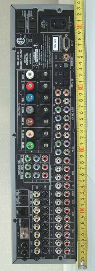
Click to zoom
Application Details
- Equipment Class
- JBP - Part 15 Class B Computing Device Peripheral
- Date of Grant
- May 20, 2004
- Application Purpose
- Original Equipment
- Date of Application
- May 20, 2004
- Equipment Note
- AV RECEIVER
- Company
- Woori Technology Inc
- Country
- South Korea
Documents & Files
Document Text
Text extracted from the exhibit documents filed with the FCC. Open a document above to read the original.
Users Manual
DPR 2005 DIGITAL PATH RECEIVER 3Introduction 4Important Safety Information 4Unpacking 5Front-Panel Controls 8Rear-Panel Connections 11Main Remote Control Functions 15Zone II Remote Control Functions 16Installation and Connections 19System Configuration 19Speaker Placement 19System Setup 20Input Setup 22Audio Setup 22Surround Setup 24Speaker Setup 26Delay Settings 27Output Level Adjustment 27Using EzSet 28Manual Output Level Adjustment 30Operation 30Basic Operation 30Source Selection 306/8-Channel Direct Input 30Volume and Tone Control 31Surround Mode Selection 31Digital Audio Playback 32Surround Mode Chart 35Tuner Operation 35Tape Recording 35Front-Panel Connections 36Output Level Trim Adjustment 37Advanced Features 37Front-Panel Display Fade 37Display Brightness 37Turn-On Volume Level 37Semi-OSD Settings 38Full-OSD Time-Out Adjustment 39Multiroom Operation 39Multiroom Setup 39Surround Amplifier Channel Assignment 40Multiroom Operation 41Configuring the Remote 41Programming Remote Codes 41Preprogrammed Code Entry 42Automatic Code Entry 42Learning Commands 43Changing Devices 44Macro Programming 46Punch-Through Configuration 47EzSet Configuration 48Renaming 49Resetting the Remote 51Troubleshooting Guide 51Processor Reset 52Technical Specifications See trademark acknowledgements on page 52. 2TABLE OF CONTENTS Typographical Conventions In order to help you use this manual with the remote control, front-panel controls and rear-panel connections, certain conventions have been used. EXAMPLE– (bold type) indicates a specific remote control or front-panel button, or rear-panel connection jack EXAMPLE– (OCR type) indicates a message that is visible on-screen or on the front-panel information display EXAMPLE– (Synchro type) indicates a message that is displayed on the remote control’s LCD screen 1– (number in a square) indicates a specific front-panel control A– (letter in a square) indicates a front-panel control that is behind the drop-down door ¡– (number in a circle) indicates a rear-panel connection a– (number in an oval) indicates a button or indicator on the remote å– (letter in an oval) indicates a button on the Zone II remote DPR 2005 OM 3/8/04 1:45 PM Page 2 INTRODUCTION Thank You for Choosing Harman Kardon ® With the purchase of a Harman Kardon DPR 2005, you are about to begin many years of listening enjoy- ment. Thanks to its completely digital path system, the DPR 2005 is truly a receiver for the new millennium. The DPR 2005 has a wide range of features and options that accommodate virtually any combination of speakers, room size and program sources. It is as easy to operate as it is to set up, but in order to take maximum advantage of the many advanced technologies within your new DPR, it is strongly recommended that you take a few minutes to read this owner’s manual. If you have any questions about this product, its instal- lation or its operation, we recommend that you contact your dealer or installer, as they are your best source of local information. You may also access a wealth of information and assistance by visiting our Web site at www.harmankardon.com. Description and Features Harman Kardon’s breakthrough Digital Path Receiver technology, of which the DPR 2005 is the second generation, keeps signals in the digital domain from the input to the output. Along with the newly designed PWM digital amplifier, this not only reduces signal degradation caused by digital-to-analog conversion stages; the increased efficiency makes it possible to reduce the DPR’s size and weight without sacrificing performance. The DPR 2005 is designed to serve as the hub of your home entertainment system, providing a variety of listening options. When playing movies or other pro- gramming from digital formats such as DVD or HDTV, the DPR decodes Dolby* Digital, Dolby Digital EX, DTS ® and DTS-ES. ® Two-channel stereo and matrix surround sources benefit from the new Pro Logic IIx technology and DTS Neo:6. ® A Harman Kardon exclu- sive in receivers is the latest version of Logic 7 ® to create a wider, more enveloping sound field and more defined surround channel positioning, regardless of the type of source material. Additional processing options include MP3 decoding when connected to a compati- ble computer and HDCD ® for enhanced CD playback. Advanced technology is also at work even when only two speakers are used.Dolby Virtual Speakermodes and Harman International’s proprietary VMAx ® are both available to create enveloping sound fields from the front left and right speakers, while Dolby Headphone circuitry creates an amazing sense of openness with headphones. Along with the many listening options, the DPR 2005 offers numerous settings that let you customize the system. A Quadruple Crossover bass management system configures each speaker group for a different crossover setting, while the assignable, wide bandwidth component video inputs may be linked to any video source. To further enhance the viewing experience with digital video sources or advanced digital video dis- plays, the DPR 2005’s A/V Sync Delay feature allows you to compensate for the loss of lip sync common in many video processing systems by delaying the audio signal independently for each input. An advanced ver- sion of Harman Kardon’s patented EzSet remote com- pletes the package, making it easier than ever to set system output levels and to program the remote to operate virtually any program source. The DPR 2005’s multizone options and a standard Zone II remote control make it possible to listen to a separate source in one room while the main home theater uses a different source. Thanks to assignable rear surround channel amplifiers, you may create a basic remote listening zone without any additional equipment. The unit’s Multiroom outputs may also be used to feed an optional, external power amplifier and volume control. For one-wire multiroom connectivity, the DPR 2005 is A-BUS Ready, ® requiring only a sin- gle Category 5/5e cable and …
Text truncated - open the document above for the full version.
Block Diagram
DPR2005-WIRING-MP02_0312.sch-1 - Fri Mar 12 11:10:22 2004 DPR2005-1005 DSP CLK BLOCK.sch-1 - Tue Mar 23 15:31:20 2004
External Photos
2000 Nemko Korea EMC Lab. WOORI Technology Inc. FCC ID: RO3DPR1005 Page 34 of 53 Test Report No.: NK2EE319.FCC FCC Certification z Front View 2000 Nemko Korea EMC Lab. WOORI Technology Inc. FCC ID: RO3DPR1005 Page 35 of 53 Test Report No.: NK2EE319.FCC FCC Certification z Rear View
ID Label/Location Info
2000 Nemko Korea EMC Lab. WOORI Technology Inc. FCC ID: RO3DPR1005 Page 26 of 53 Test Report No.: NK2EE319.FCC FCC Certification – The sample label shown shall be permanently affixed at a conspicuous location on the device and be readily visible to the user at the time of purchase. FCC ID: RO3DPR1005 (Bottom Chassis Label) Labelling Requirements
Internal Photos
2000 Nemko Korea EMC Lab. WOORI Technology Inc. FCC ID: RO3DPR1005 Page 36 of 53 Test Report No.: NK2EE319.FCC FCC Certification z Inside View (without Top Cover & Front) 2000 Nemko Korea EMC Lab. WOORI Technology Inc. FCC ID: RO3DPR1005 Page 37 of 53 Test Report No.: NK2EE319.FCC FCC Certification z Inside View (without Digital Amp. PCB) 2000 Nemko Korea EMC Lab. WOORI Technology Inc. FCC ID: RO3DPR1005 Page 38 of 53 Test Report No.: NK2EE319.FCC FCC Certification z Digital AMP. Board Top View 2000 Nemko Korea EMC Lab. WOORI Technology Inc. FCC ID: RO3DPR1005 Page 39 of 53 Test Report No.: NK2EE319.FCC FCC Certification z Digital AMP. Board Bottom View 2000 Nemko Korea EMC Lab. WOORI Technology Inc. FCC ID: RO3DPR1005 Page 40 of 53 Test Report No.: NK2EE319.FCC FCC Certification z Processor Board Top View 2000 Nemko Korea EMC Lab. WOORI Technology Inc. FCC ID: RO3DPR1005 Page 41 of 53 Test Report No.: NK2EE319.FCC FCC Certification z Processor Board Bottom View 2000 Nemko Korea EMC Lab. WOORI Technology Inc. FCC ID: RO3DPR1005 Page 42 of 53 Test Report No.: NK2EE319.FCC FCC Certification z Video Board Top View 2000 Nemko Korea EMC Lab. WOORI Technology Inc. FCC ID: RO3DPR1005 Page 43 of 53 Test Report No.: NK2EE319.FCC FCC Certification z Video Board Bottom View 2000 Nemko Korea EMC Lab. WOORI Technology Inc. FCC ID: RO3DPR1005 Page 44 of 53 Test Report No.: NK2EE319.FCC FCC Certification z Outlet Board Top View 2000 Nemko Korea EMC Lab. WOORI Technology Inc. FCC ID: RO3DPR1005 Page 45 of 53 Test Report No.: NK2EE319.FCC FCC Certification z Outlet Board Bottom View 2000 Nemko Korea EMC Lab. WOORI Technology Inc. FCC ID: RO3DPR1005 Page 46 of 53 Test Report No.: NK2EE319.FCC FCC Certification z RS232 Board Top View 2000 Nemko Korea EMC Lab. WOORI Technology Inc. FCC ID: RO3DPR1005 Page 47 of 53 Test Report No.: NK2EE319.FCC FCC Certification z RS232 Board Bottom View 2000 Nemko Korea EMC Lab. WOORI Technology Inc. FCC ID: RO3DPR1005 Page 48 of 53 Test Report No.: NK2EE319.FCC FCC Certification z SMPS Power Board Top View 2000 Nemko Korea EMC Lab. WOORI Technology Inc. FCC ID: RO3DPR1005 Page 49 of 53 Test Report No.: NK2EE319.FCC FCC Certification z SMPS Power Board Bottom View 2000 Nemko Korea EMC Lab. WOORI Technology Inc. FCC ID: RO3DPR1005 Page 50 of 53 Test Report No.: NK2EE319.FCC FCC Certification z Tuner Board Top View 2000 Nemko Korea EMC Lab. WOORI Technology Inc. FCC ID: RO3DPR1005 Page 51 of 53 Test Report No.: NK2EE319.FCC FCC Certification z Tuner Board Bottom View
Test Report
2000 Nemko Korea EMC Lab. WOORI Technology Inc. FCC ID: RO3DPR1005 Page 1 of 53 Test Report No.: NK2EE319.FCC FCC Certification Nemko Korea CO., Ltd. 300-2, Osan-Ri, Mohyun-Myun, Yongin-City, Kyungki-Do, KOREA TEL(031)322-2333 FAX(031)322-2332 FCC EVALUATION REPORT FOR CERTIFICATION Manufacture : Woori Technology Inc. Dates of Tests : May 08 – May 18, 2004 WooriTG. Bldg., 1595-1, Bongcheon-7Dong, Test Report No. : NK 2E E 319.FCC Kwanak-Gu, Seoul, Korea, 151-835 Test Site : Nemko Korea Co., Ltd. EMC site, Korea. Attn : D. S. Cho FCC ID MODEL BRAND NAME CONTACT PERSON FCC Rule Part(s) : Part 15 & 2 Classification : FCC Class B Device (AV Receiver) Port/Connector(s) : Audio INOUT (24), 8CH Direct IN (8), Pre-OUT (8), Digital Coaxial IN/OUT (4), Component Video IN/OUT (3), S-Video IN/OUT (9), Composite Video IN/OUT (9), Remote IN/OUT (2), Multi Room (1), RS-232 (1), A-BUS (1), Antenna FM/AM (2), Speaker (7), Headphone (1) The device bearing the trade name and model specified above has been shown to comply with the applicable technical standards as indicated in the measurement report and was tested in accordance with the measurement procedures specified in ANSI C63.4-1992. The test results of this report are deemed satisfactory evidence of compliance with Industry Canada Interference-Causing Equipment Standard ICES-003. I attest to the accuracy of data and all measurements reported herein were performed by me or were made under my supervision and are correct to the best of my knowledge and belief. I assume full responsibility for the completeness of these measurements and vouch for the qualifications of all persons taking them. Test By : J. Y. YU Reviewed By : H.H. Kim Engineer Manager & Chief Engineer RO3DPR1005 Harman Kardon WooriTG. Bldg., 1595-1, Bongcheon-7Dong, Kwanak-Gu, Seoul, Korea D. S. Cho 2000 Nemko Korea EMC Lab. WOORI Technology Inc. FCC ID: RO3DPR1005 Page 2 of 53 Test Report No.: NK2EE319.FCC FCC Certification TABLE OF CONTENTS SCOPE INTRODUCTION (Site Description) PRODUCT INFORMATION DESCRIPTION OF TEST (Conducted Emissions) DESCRIPTION OF TEST (Radiated Emissions) LIST OF SUPPORT EQUIPMENT USED TEST DATA (Conducted Emissions) TEST DATA (Radiated Emissions) PLOTS OF EMISSION Conducted Emissions Diagram SAMPLE CALCULATIONS ACCURACY of MEASUREMENT LIST of TEST EQUIPMENT RECOMMENDATION/CONCLUSION APPENDIX A - LABELLING REQUIREMENTS APPENDIX B - CIRCUIT DIAGRAM APPENDIX C - PHOTOGRAPHS of TEST SET-UP LINE-Conducted Test Picture Radiated Test Picture Antenna Power Conducted Test Picture APPENDIX D - EUT PHOTOGRAPHS APPENDIX E - USER’s MANUAL APPENDIX F – SCHEMATIC DIAGRAMS 3 5 6 7 8 9 10 11 13 14-17 18 19 20 21 26 27 28 29 31 32 33 52 53 2000 Nemko Korea EMC Lab. WOORI Technology Inc. FCC ID: RO3DPR1005 Page 3 of 53 Test Report No.: NK2EE319.FCC FCC Certification MEASUREMENT REPORT Scope - Measurement and determination of electromagnetic emissions (EME) of radio frequency devices including intentional and/or unintentional radiators for compliance with the technical rules and regulations of the Federal Communications Commission under FCC part 15. Responsible Party* : Contact Person : Factory: WOORI Technology Inc. Mr. Y. C. Shin Guangzhou Telefield Ltd. No. 1 Industrial Area, Zhuliao, Guanzhou Baiyun Area, Guangdong Province, P.R. China. z FCC ID: RO3DPR1005 z Trade / Model: DPR1005 z Brand Name: Harman Kardon z EUT Type: z Port/Connectors: z Classification: z Rule Part(s): z Test Procedure(s): z Dates of Test: z Place of Tests: z Test Report No.: AV R e c e i v e r Audio INOUT (24), 8CH Direct IN (8), Pre-OUT (8), Digital Coaxial IN/OUT (4), Component Video IN/OUT (3), S-Video IN/OUT (9), Composite Video IN/OUT (9), Remote IN/OUT (2), Multi Room (1), RS-232 (1), A-BUS (1), Antenna FM/AM (2), Speaker (7), Headphone (1) FCC Class B FCC Part 15 & Part 2, ICES-003 ANSI C63.4 (1992) May 08 – May 18, 2004 Nemko Korea Co., Ltd. EMC Site NK 2E E 319. FCC * NOTE: Please refer to the duties and responsibilities of the Responsible Party attached. 2000 Nemko Korea EMC Lab. WOORI Technology Inc. FCC ID: RO3DPR1005 Page 4 of 53 Test Report No.: NK2EE319.FCC FCC Certification The measurement procedure described in American National Standard for Methods of Measurement of Radio-Noise Emissions from Low-Voltage Electrical and Electronic Equipment in the Range of 9kHz to 40GHz (ANSI C63.4-1992) was used in determining radiated and conducted emissions emanating from WOORI Technology Inc. FCC ID : RO3DPR1005, AV Receiver. These measurement tests were conducted at Nemko Korea Co., Ltd. EMC Laboratory . The site address is The area of Nemko Korea Corporation LTD. EMC Test Site is located in a mountain area at 50 kilometers (30 miles) southeast and Seoul International Airport (Kimpo Airport), 30 kilometers (18miles) south-southeast from central Seoul. It is located in the valley surrounded by mountains in all directions where ambient radio signal conditions are quiet and a favorable area to measure the radio frequency interference on open field test site for the computing and ISM devices manufactures. The detailed description of the measurement facility was found to be in compliance with the requirements of 2.948 according to ANSI C63.4 on October 19, 1992. 2000 Nemko Korea EMC Lab. WOORI Technology Inc. FCC ID: RO3DPR1005 Page 5 of 53 Test Report No.: NK2EE319.FCC FCC Certification Fig. 1. The map above shows the Seoul in Korea vicinity area. The map also shows Nemko Korea Corporation Ltd. EMC Lab and Kimpo Airport. Nemko Korea Co., Ltd. 2000 Nemko Korea EMC Lab. WOORI Technology Inc. FCC ID: RO3DPR1005 Page 6 of 53 Test Report No.: NK2EE319.FCC FCC Certification PRODUCT INFORMATION Equipment Description: The Equipment Under Test (EUT) is the WOORI Technology Inc. FCC ID: RO3DPR1005, AV Receiver. Clock : 20.0 MHz (Y1), 12.288 MHz (Y2), 14.31818 MHz (Y100), 17.734 MHz (Y101), 7.2 MHz (X-Tal) Chipset(s) : CPU 100P-NEC (IC62), CS42528CQ (IC61), LC74763 (IC33), LC72131M (IC02) Port(s) : Audio INOUT (24), 8…
Text truncated - open the document above for the full version.
Test Setup Photos
2000 Nemko Korea EMC Lab. WOORI Technology Inc. FCC ID: RO3DPR1005 Page 29 of 53 Test Report No.: NK2EE319.FCC FCC Certification z Conducted Test Picture (Tuner Mode) 2000 Nemko Korea EMC Lab. WOORI Technology Inc. FCC ID: RO3DPR1005 Page 30 of 53 Test Report No.: NK2EE319.FCC FCC Certification z Conducted Test Picture (Others Mode) 2000 Nemko Korea EMC Lab. WOORI Technology Inc. FCC ID: RO3DPR1005 Page 31 of 53 Test Report No.: NK2EE319.FCC FCC Certification z Radiated Test Picture 2000 Nemko Korea EMC Lab. WOORI Technology Inc. FCC ID: RO3DPR1005 Page 32 of 53 Test Report No.: NK2EE319.FCC FCC Certification z Antenna Power Conducted Test Picture
Contact Information
Applicant
Dae-woo Lee(Engineer)
Test Firm
Nemko Korea Co., LtdHyun Kim
Technical Specifications
| # | Rule Parts | Frequency Range | Power Output |
|---|---|---|---|
| 1 | 15B | - | - |
Other Applications from Woori Technology Inc
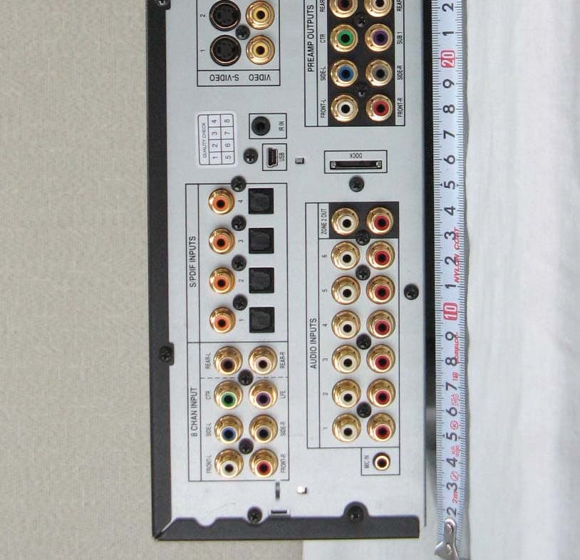
RO3MV-5
Jun 12, 2007AV Processor Preamplifier
Equipment Class
JBP - Part 15 Class B Computing Device Peripheral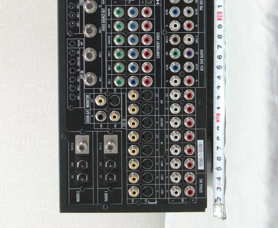
RO3AVR21EN
Sep 25, 2006AV RECEIVER
Equipment Class
JBP - Part 15 Class B Computing Device Peripheral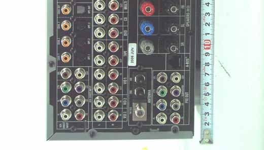
RO3AVR445
Jul 18, 2006AV RECEIVER
Equipment Class
JBP - Part 15 Class B Computing Device Peripheral
RO3AVR645
Jun 01, 2006AV RECEIVER
Equipment Class
JBP - Part 15 Class B Computing Device Peripheral
RO3AVR745
May 23, 2006AV RECEIVER
Equipment Class
JBP - Part 15 Class B Computing Device Peripheral