ROE1WTX-2470Audio-Video Transmitter
vArch, Inc. dba vArc Systems, Inc.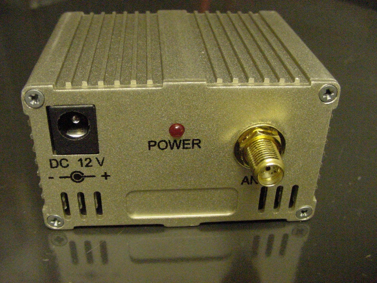
Click to zoom
Application Details
- Equipment Class
- TNB - Licensed Non-Broadcast Station Transmitter
- Date of Grant
- Jan 12, 2004
- Application Purpose
- Original Equipment
- Date of Application
- Jan 12, 2004
- Equipment Note
- Audio-Video Transmitter
- Frequency Range
- 2470.00000000 - 2470.00000000
- Country
- United States
Documents & Files
Document Text
Text extracted from the exhibit documents filed with the FCC. Open a document above to read the original.
Users Manual
Rhein Tech Laboratories Client: vArc Systems, Inc. 360 Herndon Parkway Model: 1WTX-2470 Suite 1400 FCC ID: ROE1WTX-2470 Herndon, VA 20170 Standards: FCC Part 90 http://www.rheintech.com Report Number: 2003213 37 of 51 APPENDIX K: MANUAL Please see the following pages. USER’S MANUAL iBEAM Transmitter Module Model Number: 1WTX-2470 FCC ID NUMBER: ROE1WTX-2470 vArc Systems, Inc. 280 N. 8 th Street, Suite 30 Boise, ID 83702 (208)344-8002 (208)344-8385 fax [email protected] Description and Application The iBEAM transmitter module (Model 1WTX-2470) is a long range video transmitter intended for business and industrial use. The 1WTX-2470 accepts input from an NTSC video source. The 1WTX-2470 is supplied with the following: (1) iBEAM transmitter module (1) 12 volt DC battery pack (1) charging dock (1) video camera (2) RCA video cables (1) Receiver (1) Directional antenna (1) 12 volt DC 500mA power supply The 1WTX-2470 is ideal for Residential construction Commercial construction Manufacturing Security Deployment of the System The system is shipped with power and video cables attached and is ready to use. 1. Turn the camera power switch to CAMERA. 2. Turn the transmitter power switch on. 3. For best range, direct the antenna in the genral direction of your receiver. 4. Charge the transmitter and camera batteries after use. Viewing the Video 1. Connect the receiver to the provided 12 volt DC power supply. 2. Orient the antenna towards the transmitter. 3. From the Video Out on the receiver, connect the RCA cable to any video input for recording or viewing. Notices This equipment may only be operated under a Part 90 station license issued by the FCC for Business, Industrial or Public Safety purposes. The user is responsible for operating this equipment in compliance with FCC Rules. Operation of this equipment without a valid FCC License could result in the issuance of fines to the user or seizure of the equipment. This equipment is only for use with a standard NTSC audio/video signal with pre- emphasis. Use with any other signal will void the transmitter’s FCC compliance and it will be unlawful to operate the equipment in the United States. This device is certified as a mobile device and is to be used in mobile applications only. A mobile device is defined as a transmitting device designed to be used in other than fixed locations and to be generally used in such a way that a separation distance of at least 20 cm is maintained between the transmitter's radiating structures and the body of the user and nearby persons. All users of this device must maintain a minimum distance of 20 cm between the antenna and the body of the user. Additionally, the user must maintain a minimum distance of 20 cm between the antenna and nearby persons. This device is not authorized for use in body worn configurations. Any changes or modification to this equipment without the express authorization of the manufacturer could void the user’s authority to operate this equipment. FCC ID Number: ROE1WTX-2470
Block Diagram
Rhein Tech Laboratories Client: vArc Systems, Inc. 360 Herndon Parkway Model: 1WTX-2470 Suite 1400 FCC ID: ROE1WTX-2470 Herndon, VA 20170 Standards: FCC Part 90 http://www.rheintech.com Report Number: 2003213 27 of 51 APPENDIX B: AGENCY AUTHORIZATION Please see the following page.
Block Diagram
Rhein Tech Laboratories Client: vArc Systems, Inc. 360 Herndon Parkway Model: 1WTX-2470 Suite 1400 FCC ID: ROE1WTX-2470 Herndon, VA 20170 Standards: FCC Part 90 http://www.rheintech.com Report Number: 2003213 27 of 51 APPENDIX B: AGENCY AUTHORIZATION Please see the following page.
Block Diagram
Rhein Tech Laboratories Client: vArc Systems, Inc. 360 Herndon Parkway Model: 1WTX-2470 Suite 1400 FCC ID: ROE1WTX-2470 Herndon, VA 20170 Standards: FCC Part 90 http://www.rheintech.com Report Number: 2003213 28 of 51 APPENDIX C: CONFIDENTIALITY REQUEST Please see the following page.
Block Diagram
Rhein Tech Laboratories Client: vArc Systems, Inc. 360 Herndon Parkway Model: 1WTX-2470 Suite 1400 FCC ID: ROE1WTX-2470 Herndon, VA 20170 Standards: FCC Part 90 http://www.rheintech.com Report Number: 2003213 29 of 51 APPENDIX D: ATTESTATION LETTER Please refer to the following page.
Cover Letter(s)
American Telecommunications Certification Body Inc. 6731 Whittier Ave, McLean, VA 22101 December 16, 2003 RE: vARC Systems Inc. FCC ID: ROE1WTX-2470 I have a few comments on this Application. 1) Please provide a Tune Up procedure for this device. Response : No tune up procedure is necessary for this device; please refer to the revised attestation letter, uploaded as a cover letter exhibit with this response, for an explanation. 2) Please provide a conformation that only the single frequency of 2470 is requested for this transmitter. External photographs seem to indicate that four channels are available. Response : An attestation was previously uploaded as a Cover Letter exhibit, and was entitled “2003213 vARC Systems FCC Test Report APX D Attest.pdf”. A revised version of this same exhibit was uploaded with this response. 3) Please note that F3E is reserved for FM telephony only. This device transmits both FM voice and video. Please correct requested emission designator. Response : The requested emission designator has been changed to F8W; please refer to the revised test report uploaded with this response. 4) The Circuit Description appears to indicate that this device is for use in the Part 18 ISM band. Please correct this document. Response : Reference to ISM has been removed from the circuit description; please refer to the revised operational description uploaded with this response. 5) The rationale in 14.2 of the Test Report is incorrect. Please review. Response : The rationale has been reviewed and changed as applicable; please refer to the revised test report uploaded with this response. 6) Please help me identify where in the instructions that NTSC audio and video pre-emphasis is required by the Applicant for proper operation. Response : Please refer to the revised user manual uploaded with this response. 7) Please the necessary bandwidth calculations. Please indicate how “D = .25MHz” was determined without any test data to support this conclusion. Response : Since NTSC uses a 3.58 video carrier and the test equipment was modulated 100%, the correct deviation for the video aspect is 3.58, the audio FM deviation is 250 kHz. The report has been modified to reflect this change. 8) Please indicate how the forward and reflected power was accounted for during the substitution method of transmitter spurious emission testing. Response : It has been verified using a power splitter to measure forward and reflected power that the substitution method used was valid. American Telecommunications Certification Body Inc. 6731 Whittier Ave, McLean, VA 22101 9) Additional installation instructions and RF Exposure user warnings are required within the Manual. Please review. Response : Please refer to the revised user manual uploaded with this response. 10) The Operational Description seems to indicate that this device may be capable of operation above the ~646 mW indicated on Form 731. Please review and comment. Response : Please refer to the revised operational description uploaded with this response. William H. Graff President and Examining Engineer mailto: [email protected] The items indicated above must be submitted before processing can continue on the above referenced application. Failure to provide the requested information may result in application termination. Correspondence should be considered part of the permanent submission and may be viewed from the Internet after a Grant of Equipment Authorization is issued. Please do not respond to this correspondence using the email reply button. In order for your response to be processed expeditiously, you must submit your documents through the AmericanTCB.com website. Also, please note that partial responses increase processing time and should not be submitted. Any questions about the content of this correspondence should be directed to the sender.
Cover Letter(s)
American Telecommunications Certification Body Inc. 6731 Whittier Ave, McLean, VA 22101 January 8, 2004 RE: vARC Systems Inc. FCC ID: ROE1WTX-2470 I have a few comments on this Application. 1.) The Schematics show several components (coils, potentiometers and capacitors) which are adjustable – even if only during factory assembly. Therefore it is reasonable to assume a Tune Up or adjustment procedure exists. Please provide requested exhibit. Response : Please refer to the factory-only tune up procedure uploaded with this response. 2.) Please review the necessary bandwidth calculations. Please provide measurement data showing D = .25. Response : We mistakenly submitted an incorrect “D” value with the original application. A supporting document with measurements and calculations is uploaded with this response. 3.) Additional installation instructions and RF Exposure user warnings are required within the Manual. Please review. Response : This comment is not valid, per your statement during our telephone conversation January 8, 2004. 4.) The final page of the Operational Description seems to indicate that this device may be capable of operation above 650mW. Please note that +30dBm is equal to 1 watt. Is it possible for the RF Pout to be set to a value between 0.65 and 1 watt? Response : Please refer to the revised operational description uploaded with this response. William H. Graff President and Examining Engineer mailto: [email protected] The items indicated above must be submitted before processing can continue on the above referenced application. Failure to provide the requested information may result in application termination. Correspondence should be considered part of the permanent submission and may be viewed from the Internet after a Grant of Equipment Authorization is issued. Please do not respond to this correspondence using the email reply button. In order for your response to be processed expeditiously, you must submit your documents through the AmericanTCB.com website. Also, please note that partial responses increase processing time and should not be submitted. Any questions about the content of this correspondence should be directed to the sender.
Cover Letter(s)
American Telecommunications Certification Body Inc. 6731 Whittier Ave, McLean, VA 22101 December 16, 2003 RE: vARC Systems Inc. FCC ID: ROE1WTX-2470 I have a few comments on this Application. 1) Please provide a Tune Up procedure for this device. Response : No tune up procedure is necessary for this device; please refer to the revised attestation letter, uploaded as a cover letter exhibit with this response, for an explanation. 2) Please provide a conformation that only the single frequency of 2470 is requested for this transmitter. External photographs seem to indicate that four channels are available. Response : An attestation was previously uploaded as a Cover Letter exhibit, and was entitled “2003213 vARC Systems FCC Test Report APX D Attest.pdf”. A revised version of this same exhibit was uploaded with this response. 3) Please note that F3E is reserved for FM telephony only. This device transmits both FM voice and video. Please correct requested emission designator. Response : The requested emission designator has been changed to F8W; please refer to the revised test report uploaded with this response. 4) The Circuit Description appears to indicate that this device is for use in the Part 18 ISM band. Please correct this document. Response : Reference to ISM has been removed from the circuit description; please refer to the revised operational description uploaded with this response. 5) The rationale in 14.2 of the Test Report is incorrect. Please review. Response : The rationale has been reviewed and changed as applicable; please refer to the revised test report uploaded with this response. 6) Please help me identify where in the instructions that NTSC audio and video pre-emphasis is required by the Applicant for proper operation. Response : Please refer to the revised user manual uploaded with this response. 7) Please the necessary bandwidth calculations. Please indicate how “D = .25MHz” was determined without any test data to support this conclusion. Response : Since NTSC uses a 3.58 video carrier and the test equipment was modulated 100%, the correct deviation for the video aspect is 3.58, the audio FM deviation is 250 kHz. The report has been modified to reflect this change. 8) Please indicate how the forward and reflected power was accounted for during the substitution method of transmitter spurious emission testing. Response : It has been verified using a power splitter to measure forward and reflected power that the substitution method used was valid. American Telecommunications Certification Body Inc. 6731 Whittier Ave, McLean, VA 22101 9) Additional installation instructions and RF Exposure user warnings are required within the Manual. Please review. Response : Please refer to the revised user manual uploaded with this response. 10) The Operational Description seems to indicate that this device may be capable of operation above the ~646 mW indicated on Form 731. Please review and comment. Response : Please refer to the revised operational description uploaded with this response. William H. Graff President and Examining Engineer mailto: [email protected] The items indicated above must be submitted before processing can continue on the above referenced application. Failure to provide the requested information may result in application termination. Correspondence should be considered part of the permanent submission and may be viewed from the Internet after a Grant of Equipment Authorization is issued. Please do not respond to this correspondence using the email reply button. In order for your response to be processed expeditiously, you must submit your documents through the AmericanTCB.com website. Also, please note that partial responses increase processing time and should not be submitted. Any questions about the content of this correspondence should be directed to the sender.
Cover Letter(s)
American Telecommunications Certification Body Inc. 6731 Whittier Ave, McLean, VA 22101 January 8, 2004 RE: vARC Systems Inc. FCC ID: ROE1WTX-2470 I have a few comments on this Application. 1.) The Schematics show several components (coils, potentiometers and capacitors) which are adjustable – even if only during factory assembly. Therefore it is reasonable to assume a Tune Up or adjustment procedure exists. Please provide requested exhibit. Response : Please refer to the factory-only tune up procedure uploaded with this response. 2.) Please review the necessary bandwidth calculations. Please provide measurement data showing D = .25. Response : We mistakenly submitted an incorrect “D” value with the original application. A supporting document with measurements and calculations is uploaded with this response. 3.) Additional installation instructions and RF Exposure user warnings are required within the Manual. Please review. Response : This comment is not valid, per your statement during our telephone conversation January 8, 2004. 4.) The final page of the Operational Description seems to indicate that this device may be capable of operation above 650mW. Please note that +30dBm is equal to 1 watt. Is it possible for the RF Pout to be set to a value between 0.65 and 1 watt? Response : Please refer to the revised operational description uploaded with this response. William H. Graff President and Examining Engineer mailto: [email protected] The items indicated above must be submitted before processing can continue on the above referenced application. Failure to provide the requested information may result in application termination. Correspondence should be considered part of the permanent submission and may be viewed from the Internet after a Grant of Equipment Authorization is issued. Please do not respond to this correspondence using the email reply button. In order for your response to be processed expeditiously, you must submit your documents through the AmericanTCB.com website. Also, please note that partial responses increase processing time and should not be submitted. Any questions about the content of this correspondence should be directed to the sender.
Cover Letter(s)
American Telecommunications Certification Body Inc. 6731 Whittier Ave, McLean, VA 22101 January 8, 2004 RE: vARC Systems Inc. FCC ID: ROE1WTX-2470 I have a few comments on this Application. 1.) The Schematics show several components (coils, potentiometers and capacitors) which are adjustable – even if only during factory assembly. Therefore it is reasonable to assume a Tune Up or adjustment procedure exists. Please provide requested exhibit. 2.) Please review the necessary bandwidth calculations. Please provide measurement data showing D = .25. 3.) Additional installation instructions and RF Exposure user warnings are required within the Manual. Please review. 4.) The final page of the Operational Description seems to indicate that this device may be capable of operation above 650mW. Please note that +30dBm is equal to 1 watt. Is it possible for the RF Pout to be set to a value between 0.65 and 1 watt? William H. Graff President and Examining Engineer mailto: [email protected] The items indicated above must be submitted before processing can continue on the above referenced application. Failure to provide the requested information may result in application termination. Correspondence should be considered part of the permanent submission and may be viewed from the Internet after a Grant of Equipment Authorization is issued. Please do not respond to this correspondence using the email reply button. In order for your response to be processed expeditiously, you must submit your documents through the AmericanTCB.com website. Also, please note that partial responses increase processing time and should not be submitted. Any questions about the content of this correspondence should be directed to the sender.
Cover Letter(s)
American Telecommunications Certification Body Inc. 6731 Whittier Ave, McLean, VA 22101 December 16, 2003 RE: vARC Systems Inc. FCC ID: ROE1WTX-2470 I have a few comments on this Application. 1.) Please provide a Tune Up procedure for this device. 2.) Please provide a conformation that only the single frequency of 2470 is requested for this transmitter. External photographs seem to indicate that four channels are available. 3.) Please note that F3E is reserved for FM telephony only. This device transmits both FM voice and video. Please correct requested emission designator. 4.) The Circuit Description appears to indicate that this device is for use in the Part 18 ISM band. Please correct this document. 5.) The rationale in 14.2 of the Test Report is incorrect. Please review. 6.) Please help me identify where in the instructions that NTSC audio and video pre-emphasis is required by the Applicant for proper operation. 7.) Please the necessary bandwidth calculations. Please indicate how “D = .25MHz” was determined without any test data to support this conclusion. 8.) Please indicate how the forward and reflected power was accounted for during the substitution method of transmitter spurious emission testing. 9.) Additional installation instructions and RF Exposure user warnings are required within the Manual. Please review. 10.) The Operational Description seems to indicate that this device may be capable of operation above the ~646 mW indicated on Form 731. Please review and comment. William H. Graff President and Examining Engineer mailto: [email protected] The items indicated above must be submitted before processing can continue on the above referenced application. Failure to provide the requested information may result in application termination. Correspondence should be considered part of the permanent submission and may be viewed from the Internet after a Grant of Equipment Authorization is issued. Please do not respond to this correspondence using the email reply button. In order for your response to be processed expeditiously, you must submit your documents through the AmericanTCB.com website. Also, please note that partial responses increase processing time and should not be submitted. Any questions about the content of this correspondence should be directed to the sender.
External Photos
Rhein Tech Laboratories Client: vArc Systems, Inc. 360 Herndon Parkway Model: 1WTX-2470 Suite 1400 FCC ID: ROE1WTX-2470 Herndon, VA 20170 Standards: FCC Part 90 http://www.rheintech.com Report Number: 2003213 40 of 51 APPENDIX M: EXTERNAL PHOTOGRAPHS PHOTOGRAPH 4: FRONT VIEW Rhein Tech Laboratories Client: vArc Systems, Inc. 360 Herndon Parkway Model: 1WTX-2470 Suite 1400 FCC ID: ROE1WTX-2470 Herndon, VA 20170 Standards: FCC Part 90 http://www.rheintech.com Report Number: 2003213 41 of 51 PHOTOGRAPH 5: BACK VIEW Rhein Tech Laboratories Client: vArc Systems, Inc. 360 Herndon Parkway Model: 1WTX-2470 Suite 1400 FCC ID: ROE1WTX-2470 Herndon, VA 20170 Standards: FCC Part 90 http://www.rheintech.com Report Number: 2003213 42 of 51 PHOTOGRAPH 6: ANTENNA Rhein Tech Laboratories Client: vArc Systems, Inc. 360 Herndon Parkway Model: 1WTX-2470 Suite 1400 FCC ID: ROE1WTX-2470 Herndon, VA 20170 Standards: FCC Part 90 http://www.rheintech.com Report Number: 2003213 43 of 51 PHOTOGRAPH 7: BATTERY
ID Label/Location Info
Rhein Tech Laboratories Client: vArc Systems, Inc. 360 Herndon Parkway Model: 1WTX-2470 Suite 1400 FCC ID: ROE1WTX-2470 Herndon, VA 20170 Standards: FCC Part 90 http://www.rheintech.com Report Number: 2003213 32 of 51 APPENDIX G: LABEL INFORMATION A sample of the FCC ID label, which is placed on the bottom of the transmitter, appears below. The following page shows a photograph of the label location on the EUT. FCC ID Label Sample Rhein Tech Laboratories Client: vArc Systems, Inc. 360 Herndon Parkway Model: 1WTX-2470 Suite 1400 FCC ID: ROE1WTX-2470 Herndon, VA 20170 Standards: FCC Part 90 http://www.rheintech.com Report Number: 2003213 33 of 51 PHOTOGRAPH 1: FCC ID LABEL LOCATION FCC ID LABEL HERE
Internal Photos
Rhein Tech Laboratories Client: vArc Systems, Inc. 360 Herndon Parkway Model: 1WTX-2470 Suite 1400 FCC ID: ROE1WTX-2470 Herndon, VA 20170 Standards: FCC Part 90 http://www.rheintech.com Report Number: 2003213 44 of 51 APPENDIX N: INTERNAL PHOTOGRAPHS PHOTOGRAPH 8: TOP WITH CASE REMOVED Rhein Tech Laboratories Client: vArc Systems, Inc. 360 Herndon Parkway Model: 1WTX-2470 Suite 1400 FCC ID: ROE1WTX-2470 Herndon, VA 20170 Standards: FCC Part 90 http://www.rheintech.com Report Number: 2003213 45 of 51 PHOTOGRAPH 9: BOTTOM SHOWING HEAT SHIELD Rhein Tech Laboratories Client: vArc Systems, Inc. 360 Herndon Parkway Model: 1WTX-2470 Suite 1400 FCC ID: ROE1WTX-2470 Herndon, VA 20170 Standards: FCC Part 90 http://www.rheintech.com Report Number: 2003213 46 of 51 PHOTOGRAPH 10: BOTTOM OF SHIELD Rhein Tech Laboratories Client: vArc Systems, Inc. 360 Herndon Parkway Model: 1WTX-2470 Suite 1400 FCC ID: ROE1WTX-2470 Herndon, VA 20170 Standards: FCC Part 90 http://www.rheintech.com Report Number: 2003213 47 of 51 PHOTOGRAPH 11: TOP OF SHIELD Rhein Tech Laboratories Client: vArc Systems, Inc. 360 Herndon Parkway Model: 1WTX-2470 Suite 1400 FCC ID: ROE1WTX-2470 Herndon, VA 20170 Standards: FCC Part 90 http://www.rheintech.com Report Number: 2003213 48 of 51 PHOTOGRAPH 12: TOP OF PCB1 Rhein Tech Laboratories Client: vArc Systems, Inc. 360 Herndon Parkway Model: 1WTX-2470 Suite 1400 FCC ID: ROE1WTX-2470 Herndon, VA 20170 Standards: FCC Part 90 http://www.rheintech.com Report Number: 2003213 49 of 51 PHOTOGRAPH 13: BOTTOM OF PCB1 Rhein Tech Laboratories Client: vArc Systems, Inc. 360 Herndon Parkway Model: 1WTX-2470 Suite 1400 FCC ID: ROE1WTX-2470 Herndon, VA 20170 Standards: FCC Part 90 http://www.rheintech.com Report Number: 2003213 50 of 51 PHOTOGRAPH 14: TOP OF PCB2 Rhein Tech Laboratories Client: vArc Systems, Inc. 360 Herndon Parkway Model: 1WTX-2470 Suite 1400 FCC ID: ROE1WTX-2470 Herndon, VA 20170 Standards: FCC Part 90 http://www.rheintech.com Report Number: 2003213 51 of 51 PHOTOGRAPH 15: BOTTOM OF PCB2
Internal Photos
Rhein Tech Laboratories Client: vArc Systems, Inc. 360 Herndon Parkway Model: 1WTX-2470 Suite 1400 FCC ID: ROE1WTX-2470 Herndon, VA 20170 Standards: FCC Part 90 http://www.rheintech.com Report Number: 2003213 44 of 51 APPENDIX N: INTERNAL PHOTOGRAPHS PHOTOGRAPH 8: TOP WITH CASE REMOVED Rhein Tech Laboratories Client: vArc Systems, Inc. 360 Herndon Parkway Model: 1WTX-2470 Suite 1400 FCC ID: ROE1WTX-2470 Herndon, VA 20170 Standards: FCC Part 90 http://www.rheintech.com Report Number: 2003213 45 of 51 PHOTOGRAPH 9: BOTTOM SHOWING HEAT SHIELD Rhein Tech Laboratories Client: vArc Systems, Inc. 360 Herndon Parkway Model: 1WTX-2470 Suite 1400 FCC ID: ROE1WTX-2470 Herndon, VA 20170 Standards: FCC Part 90 http://www.rheintech.com Report Number: 2003213 46 of 51 PHOTOGRAPH 10: BOTTOM OF SHIELD Rhein Tech Laboratories Client: vArc Systems, Inc. 360 Herndon Parkway Model: 1WTX-2470 Suite 1400 FCC ID: ROE1WTX-2470 Herndon, VA 20170 Standards: FCC Part 90 http://www.rheintech.com Report Number: 2003213 47 of 51 PHOTOGRAPH 11: TOP OF SHIELD Rhein Tech Laboratories Client: vArc Systems, Inc. 360 Herndon Parkway Model: 1WTX-2470 Suite 1400 FCC ID: ROE1WTX-2470 Herndon, VA 20170 Standards: FCC Part 90 http://www.rheintech.com Report Number: 2003213 48 of 51 PHOTOGRAPH 12: TOP OF PCB1 Rhein Tech Laboratories Client: vArc Systems, Inc. 360 Herndon Parkway Model: 1WTX-2470 Suite 1400 FCC ID: ROE1WTX-2470 Herndon, VA 20170 Standards: FCC Part 90 http://www.rheintech.com Report Number: 2003213 49 of 51 PHOTOGRAPH 13: BOTTOM OF PCB1 Rhein Tech Laboratories Client: vArc Systems, Inc. 360 Herndon Parkway Model: 1WTX-2470 Suite 1400 FCC ID: ROE1WTX-2470 Herndon, VA 20170 Standards: FCC Part 90 http://www.rheintech.com Report Number: 2003213 50 of 51 PHOTOGRAPH 14: TOP OF PCB2 Rhein Tech Laboratories Client: vArc Systems, Inc. 360 Herndon Parkway Model: 1WTX-2470 Suite 1400 FCC ID: ROE1WTX-2470 Herndon, VA 20170 Standards: FCC Part 90 http://www.rheintech.com Report Number: 2003213 51 of 51 PHOTOGRAPH 15: BOTTOM OF PCB2
RF Exposure Info
Rhein Tech Laboratories Client: vArc Systems, Inc. 360 Herndon Parkway Model: 1WTX-2470 Suite 1400 FCC ID: ROE1WTX-2470 Herndon, VA 20170 Standards: FCC Part 90 http://www.rheintech.com Report Number: 2003213 30 of 51 APPENDIX E: ANTENNA SPECIFICATIONS Please refer to the following page. 5.5 dBi Gain 2.4 GHz Omni Directional Antenna Description The 5.5 dBi 2.4 GHz Omni Directional Antenna features a 360 degree horizontal transmission pattern and a 50 degree vertical transmission pattern. The transmit/receive element can be tilted in relation to the base to direct signal where it is needed (0, 45, 90 degrees). Specifications Parameter Min Typ Max Units Frequency Range 2400 2485 MHz Gain 5.5 dBi VSWR 1.5:1 Impedance 50 OHM Input Power 10 W Operating Temperature -10 +60 Deg C Weight 0.9 (25) oz (gr) Dimension 7.75 x 0.5D (197 x 12.7D) in (mm) Antenna Plots @ 2450 MHz
RF Exposure Info
Rhein Tech Laboratories Client: vArc Systems, Inc. 360 Herndon Parkway Model: 1WTX-2470 Suite 1400 FCC ID: ROE1WTX-2470 Herndon, VA 20170 Standards: FCC Part 90 http://www.rheintech.com Report Number: 2003213 30 of 51 APPENDIX E: ANTENNA SPECIFICATIONS Please refer to the following page. 5.5 dBi Gain 2.4 GHz Omni Directional Antenna Description The 5.5 dBi 2.4 GHz Omni Directional Antenna features a 360 degree horizontal transmission pattern and a 50 degree vertical transmission pattern. The transmit/receive element can be tilted in relation to the base to direct signal where it is needed (0, 45, 90 degrees). Specifications Parameter Min Typ Max Units Frequency Range 2400 2485 MHz Gain 5.5 dBi VSWR 1.5:1 Impedance 50 OHM Input Power 10 W Operating Temperature -10 +60 Deg C Weight 0.9 (25) oz (gr) Dimension 7.75 x 0.5D (197 x 12.7D) in (mm) Antenna Plots @ 2450 MHz
RF Exposure Info
Rhein Tech Laboratories Client: vArc Systems, Inc. 360 Herndon Parkway Model: 1WTX-2470 Suite 1400 FCC ID: ROE1WTX-2470 Herndon, VA 20170 Standards: FCC Part 90 http://www.rheintech.com Report Number: 2003213 26 of 51 APPENDIX A: RF EXPOSURE From FCC 1.1310 Table 1(B), the maximum permissible RF exposure for a transmitter operating at this frequency in an uncontrolled environment is 1 mW/cm 2 . The electric field generated for a 1 mW/cm 2 exposure (S) is calculated as follows: )4/()( 2 dGPS×××=π where: S = Power density P = Transmitter conducted power in watts G = Numeric gain d = distance to radiation center Fundamental Operating Frequency: 2470 MHz Maximum Rated Output Power: 1.0 Watts (1000 mW) Measured Maximum Output Power: 0.646 Watts (646 mW) Antenna Gain =5.5 dBi; Numeric Gain = 3.55 S = (1000 X 3.55)/ (4 x Pi X 20 2 ) = 0.7 mW/cm 2 Under normal operating conditions, the antenna is designed to maintain a separation distance of 20 cm from all persons. The EUT is for mobile configurations. Calculated Power Density: Antenna Gain = 5.5 dBi Conducted Power (mW) = 1000 Separation Distance = 20 cm FCC Power density Limit Calculated Power density at 20 cm 1 mW/cm 2 0.7 wW/cm 2
Test Report
Engineering and Testing for EMC and Safety Compliance C C E E R R T T I I F F I I C C A A T T I I O O N N R R E E P P O O R R T T FCC PART 90 vARC Systems, Inc. 280 N. 8 th Street, Suite 30 Boise, Idaho 83702 MODEL: 1WTX-2470 FCC ID: ROE1WTX-2470 December 8, 2003 STANDARDS REFERENCED FOR THIS REPORT PART 2: 2001 FREQUENCY ALLOCATIONS AND RADIO TREATY MATTERS; GENERAL RULES AND REGULATIONS PART 15: 2003 RADIO FREQUENCY DEVICES - §15.109: RADIATED EMISSIONS LIMITS PART 90: 2001 PRIVATE LAND MOBILE RADIO SERVICES ANSI C63.4-1992 STANDARD FORMAT MEASUREMENT/TECHNICAL REPORT PERSONAL COMPUTER AND PERIPHERALS ANSI/TIA/EIA603- 2002 L AND MOBILE FM OR PM COMMUNICATIONS EQUIPMENT MEASUREMENT AND PERFORMANCE STANDARDS Frequency Range Output Power Conducted (W) Frequency Tolerance (ppm) Emission Designator 2470 MHz 0.646 3.4 15M7F8W REPORT PREPARED BY TEST ENGINEER: DAN BALTZELL Document Number: 2003213 / QRTL03-173 No part of t…
Text truncated - open the document above for the full version.
Contact Information
Applicant
Tom Allen
Technical Contact
Rhein Tech LaboratoriesDesmond Fraser
[email protected]703 689 0368
360 Herndon Parkway · Herndon, Virginia · United States
Test Firm
Rhein Tech Laboratories, Inc.Rick McMurray
Technical Specifications
| # | Rule Parts | Frequency Range | Power Output | Emission | Tolerance |
|---|---|---|---|---|---|
| 1 | 90 | 2.47 GHz - 2.47 GHz | 650.00 mW | 5M40F8W | 3.4000000000 ppm |