RQL232695ULTRA-SMALL TRANSMITTER
Larco, Division of Atek Companies, Inc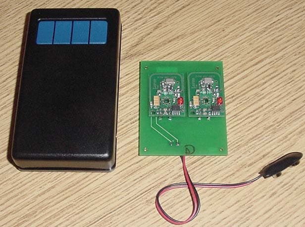
Click to zoom
Application Details
- Equipment Class
- DSC - Part 15 Security/Remote Control Transmitter
- Date of Grant
- Dec 21, 2003
- Application Purpose
- Original Equipment
- Date of Application
- Dec 21, 2003
- Equipment Note
- ULTRA-SMALL TRANSMITTER
- Frequency Range
- 433.42000000 - 434.42000000
- Country
- United States
Documents & Files
Document Text
Text extracted from the exhibit documents filed with the FCC. Open a document above to read the original.
Users Manual
1902 13th Street SE • PO Box 547 • Brainerd, MN 56401 phone 218-829-9797 • toll free phone 800-523-6996 • fax 218-829-0139 • toll free fax 800-589-3705 www.larcomfg.com AD14-December 2003 Ultra-Small Receiver Installation NOTE: Read this manual in its entirety before installing any Larco transmitter or receiver. It is important to complete the programming procedure before installing the receiver in its final location. The installer must have access to the receiver’s programming button and must be able to view the receiver’s LED (Light Emitting Diode) during the programming process. System The Larco Ultra-Small Transmitters and Receivers operate at 433.92 MHz (acceptable in the United States, Canada and any European Union member state) and employ code-hopping technology, reducing false activations. The receiver only operates after learning a transmitter’s signal through the simple procedure outlined on the next page. This programming procedure eliminates the need to set dip switches and involves a simple press of the programming button located on the top cover of the receiver (see drawings below for details). Installation NOTE: Complete the programming procedure on the next page before placing the receiver in its final location. 1. Mount the receiver in a location so that the antenna is not surrounded by metal. Metal attenuates RF signals causing a reduction in range and inconsistency of signal reception. Door operator motors and controls may also cause radio frequency interference. Locate the receiver away from the door control’s motor and power supply. If the receiver is mounted in a metal enclosure, drill a hole in the enclosure and thread as much of the antenna as possible through the hole. This reduces the effects the metal enclosure will have on the receiver’s reception. 2. The receiver comes equipped with a wiring harness for easy installation. Follow the color- coding scheme below the diagram at right. Diagram 2: Receiver Wiring Harness. Yellow Wire: Normally Closed Relay Output Brown Wire: Normally Closed Relay Output Common Connection Purple Wire: 12 VDC Power (NOTE: DO NOT connect 12 VAC Power) Black Wire: Ground Red Wire: 24VAC/24VDC Power Brown wire with White Stripe: Normally Open Relay Output Common Connection Orange Wire: Normally Open Relay Output Diagram 1: Receiver (left) and Transmitter (right) Dimensional Diagrams Ultra-Small Receiver Installation, Cont’d Programming Procedures NOTE: Prior to programming, make sure the receiver’s LED blinks red when power is applied. If the receiver’s LED is not blinking red, disconnect then reconnect the power. Programming transmitter(s) into the receiver’s memory: The receiver can learn up to 12 transmitters. Follow the steps below to program your receiver. Repeat steps 1-3 for each transmitter. 1. Press the receiver’s programming button for less than 2 seconds and release. The LED should change from flashing red to solid green, indicating the receiver has entered its programming mode. 2. Activate and release the transmitter once and confirm that the receiver’s LED changes to red. This indicates the receiver is learning the transmitter’s code. 3. Wait a few seconds and then activate the transmitter a second time. The receiver’s LED should now blink green several times indicating that it is ending its learning procedure. When the procedure has ended, the LED should be flashing red. Programming the receiver’s output activation time: When the receiver is activated, its outputs will stay in the minimum activation state for approximately 1.5 seconds (default). This time can be adjusted to stay in the activation state for up to 4 hours. Follow the steps below to adjust the receiver’s output activation time. 1. Press the receiver’s programming button for 4 seconds and release. The LED should be solid red. This indicates the receiver is in the activation time programming mode. 2. Activate and release the transmitter. 3. When the desired time has elapsed (up to 4 hours) activate the transmitter again. The receiver’s LED should blink green several times indicating it is ending the procedure. When the procedure has ended, the LED should be flashing red. The receiver and transmitter comply with FCC part 15/15.231-2001, Industry Canada RSS-210-2003, EN55022A-2000, EN55024-2001, EN300-220-3 V1.1.1-2000, and EN301-489-1 V1.2.1-2000. Operation is subject to the following two conditions: (1) This device may not cause harmful interference, and (2) this device must accept any inerference received, including interference that may cause undesired operation. This product may be susceptible to local transmissions being generated near the transmitter’s fundamental frequency. Testing has shown some susceptibility in a frequency range of 416-440 MHz. NOTE: This equipment has been tested and found to comply with the limits for a Class B digital device, pursuant to part 15 of the FCC rules. These limits are designed to provide reasonable protection against harmful interference in a residential installation. This equipment generates, uses and can radiate radio frequency energy and, if not installed and used in accordance with the instructions, may cause harmful interference to radio communications. However, there is no guarantee that interference will not occur in a particular installation. If this equipment does cause harmful interference to radio or television reception, which can be determined by turning the equipment off and on, the user is encouraged to try to correct interference by one or more of the following measures: (a) Reorient or relocate the receiving antenna. (b) Increase the separation between the equipment and receiver. (c) Connect the equipment into an outlet on a circuit different from that to which the receiver is connected (d) Consult the dealer or an experienced radio/TV technician for help. The user is cautioned that any internal modifications, either replacement of or modification of any component, of the transmitter or receiver could vi…
Text truncated - open the document above for the full version.
Block Diagram
LARCO DIVISION OF ACROMETAL ULTRA SMALL TRANSMITTER BLOCK DIAGRAM 1 of 1 International Certification Services, Inc.
External Photos
LARCO DIVISION OF ACROMETAL ULTRA SMALL TRANSMITTER EXTERNAL EUT PHOTOS 4 INCH VERSION JAMB SWITCH 6 INCH VERSION BARE BOARD REMOTE 2 SWITCH VERSION 1 of 2 International Certification Services, Inc. Remote 4 Switch Ultra Small Transmitter version 2 of 2 International Certification Services, Inc.
ID Label/Location Info
Labels for the Larco Transmitter (Bare Board version as well as each of the five packaged versions) Ultra-Small 433MHz Transmitter Label for use on the transmitter itself and on each of the five package versions: The version for the transmitter is 2” x 0.5” with the writing centered in the right half of the label. The left side is left unprinted and is used to wrap around the battery cable of the transmitter and adhere to the back of the other side of the label. The packaged version is 1.25” x 0.75” and is affixed to the back side of the plastic box of each of the five package versions. FCC ID RQL 232695 CANADA: RSS/CNR YYY ZZZZ-ZZZ-ZZZZZ ULTRA-SMALL 233882 1 of 2 International Certification Services, Inc. LARCO DIVISION OF ACROMETAL ULTRA SMALL TRANSMITTER FCC LABEL LOCATION 4 INCH VERSION JAMB SWITCH 6 INCH VERSION BARE BOARD REMOTE 2, 4 SWITCH VERSION Label for bare board transmitter 2 of 2 International Certification Services, Inc.
Internal Photos
LARCO DIVISION OF ACROMETAL ULTRA SMALL TRANSMITTER INTERNAL EUT PHOTOS Internal PC Foil Antenna Transmitter Bare Board 1 of 6 International Certification Services, Inc. LARCO DIVISION OF ACROMETAL ULTRA SMALL TRANSMITTER INTERNAL EUT PHOTOS 4 Inch Switch 2 of 6 International Certification Services, Inc. LARCO DIVISION OF ACROMETAL ULTRA SMALL TRANSMITTER INTERNAL EUT PHOTOS 6 Inch Switch 3 of 6 International Certification Services, Inc. LARCO DIVISION OF ACROMETAL ULTRA SMALL TRANSMITTER INTERNAL EUT PHOTOS Jamb Switch 4 of 6 International Certification Services, Inc. LARCO DIVISION OF ACROMETAL ULTRA SMALL TRANSMITTER INTERNAL EUT PHOTOS Remote Switch (2 button) 5 of 6 International Certification Services, Inc. LARCO DIVISION OF ACROMETAL ULTRA SMALL TRANSMITTER INTERNAL EUT PHOTOS Remote Switch (4 button) 6 of 6 International Certification Services, Inc.
Operational Description
OPERATIONAL DESCRIPTION When the transmit button is pushed the code hopping IC (“pulse modulator” in the above picture) is enabled. This chip sends out a series of data bits corresponding to its programmed and individual transmitter ID combined with the programmed company ID according to a code hopping algorithm, plus a few extra data bits that tell which of the enable pins to the code hopping chip were enabled. There are four enables on the chip but we only use one for most of our applications and two for the dual channel remote transmitter and two again on each of the two transmitter boards in the four channel remote transmitter. The bits coming out of the code hoping IC turn the saw filer on and off so that a “1” data bit turns the transmitter “on” and a “0” bit turns the transmitter “off”. A transistor in the output amplifies the signal. A capacitor and resistor (not shown) take the original button press and extend the enable time to several seconds (around 25s) so the transmitter can repeat the message many times making it more likely that the receiver will get the message.
Schematics
LARCO DIVISION OF ACROMETAL ULTRA SMALL TRANSMITTER SCHEMATIC 1 of 1 International Certification Services, Inc.
Test Report
TEST REPORT #211103 STANDARD: FCC PART 15 SUBPART C--INTENTIONAL RADIATORS SECTION 15. 231 PERIODIC OPERATION IN THE BAND 40.66-40.70 MHZ AND ABOVE 70 MHZ EQUIPMENT TESTED: LARCO DIVISION OF ACROMETAL MODEL: ULTRASMALL TRANSMITTER TEST DATE: 21 NOVEMBER 2003 INTERNATIONAL CERTIFICATION SERVICES, INC. 1100 Falcon Avenue Glencoe, MN 55336 Tele: 320-864-4444 Fax: 320-864-6611 2 of 16 International Certification Services, Inc. Prepared for: Test agent: Test location: Prepared by: . Larco Division of Acrometal 1902 13 th Street SE Brainerd, MN 56401 International Certification Services, Inc. 1100 Falcon Avenue Glencoe, MN 55336 Tele: 320-864-4444 Fax: 320-864-6611 International Certification Services, Inc. 1100 Falcon Avenue Glencoe, MN 55336 Tele: 320-864-4444 Fax: 320-864-6611 International Certification Services, Inc. 1100 Falcon Avenue Glencoe, MN 55336 International Certification Services represents to the client that testing is done in accordance with standard procedures applicable and that reported test results are accurate within generally accepted commercial ranges of accuracy. This report only applies to the specific samples tested under stated test conditions. It is the manufacturer’s responsibility to assure that additional production units of this model are manufactured with identical electrical and mechanical components. International Certification Services shall have no liability for any deductions, inferences or generalizations drawn by the client or others from this report. This report is the confidential property of the client. As a mutual protection to our clients, the public and ourselves, extracts from the test report shall not be reproduced except in full without our written approval. 3 of 16 International Certification Services, Inc. 1.0 TEST SUMMARY TEST REPORT: #211103 COMPANY: AGENT:International Certification Services, Inc. PHONE:320-864-4444 TEST DATE: EQUIPMENT UNDER TEST: GENERAL TEST SUMMARY: VERIFICATION / CERTIFICATION STATUS: MODIFICATIONS NECESSARY: TESTED AND WRITTEN BY Duane R. Bagdons Larco Division of Acrometal 21 November, 2003 Ultra Small Transmitter (433.92 Mhz) The testing was performed at International Certification Services, Inc. at 1100 Falcon Ave, Glencoe, MN 55336 The Larco Division of Acrometal, Model: Ultra Small Transmitter (433.92 Mhz) was found to be in compliance with the FCC Part 15 Subpart C, Section 15.231 requirements. None 4 of 16 International Certification Services, Inc. Applicable Standards 47 CFR Ch.1 (10-1-98 Edition) FCC Part 15Radio Frequency Devices Subpart CIntentional Radiators Section 15.231Periodic operation in the band 40.66-40.70 Mhz and above 70 Mhz. 2.1Referenced Standards ANSI C63.4-2000Methods of Measurement of Radio-Noise Emissions from Low-Voltage Electrical and Electronic Equipment in the Range of 9 Khz to 40 Ghz. 2.2 Equipment Units Tested The equipment tested is a very small transmitter that is packaged 6 different versions. The same transmitter board is used in each configuration. The different packages listed in this report are 1) the Jamb Switch, 2) the 4 inch switch, 3) the 6 inch switch, 4) the Remote 2 switch version 5) Remote 4 switch Version and 6) a Bare Board Transmitter. The only difference between these 6 models are the enclosure packaging and the Remote devices have a daughter board added to include 2 push button switches or 4 push button switches to control output devices. The transmitter pc board is identical on all of the models. The Remote 4 Switch version has two identical transmitters in the same package. Photos of each of these devices are shown below: 1) Jamb Switch 2) 4 inch Switch 5 of 16 International Certification Services, Inc. 2.3 Equipment and Cable Configuration See photo of the EUT test configuration setup in Attachment A 2.4 List of Test Equipment 6) Bare Transmitter Board 4) Remote Two Switch Transmitter Test Equipment Spectrum Analyzer Preamp Preamp Dipole Antenna Biconalog Periodic Antenna Ridge Guide Antenna Signal Generator Multimeter Temperature Chamber Temperature Probe Near Field Probe Spectrum Analyzer Model Hewlett Packard 8566B MiniCircuits ZKL-1042j Schwartzbeck UHAP-10dB Electro Metrics EM-6917B EMCO 3115 Wavetek 2520 Fluke 70 III Thermotron S-1.2 Omega HH23 EMCO 7405 HP8591E S/N 2115A00853 DP10150323 164 106 2483 6271013 78021032 Calibration Due Date 10/17/04 10/16/04 N/A 03/18/04 03/25/04 06/04/04 N/A N/A 09/13/04 N/A 11/13/04 5) Remote 4 Switch Transmitter 3) 6 inch Switch 6 of 16 International Certification Services, Inc. Measurement cable losses, and antenna correction factors are included in the data sheets. The Resolution BW was set at 1 Mhz and the Video BW was set at 1 Hz with a Span of 0 Hz to perform the correct average detected measurements. 2.5 Units of Measurement. All measurements were taken in dBuV/m with the antenna located at 3 meters distance from the EUT. Frequency measurements are recorded in Mhz 2.6TEST FACILITY The open area test site (OATS) and conducted measurement facility used to collect the data was International Certification Services, Inc. at 1100 Falcon Ave. in Glencoe, MN 55336. This site has been certified to be in compliance with the normalized site attenuation section of CISPR 16-1. (See FCC Registration number: 91103 and Industry Canada File number: IC 3701.) International Certification Services, Inc. is also a registered appointed EMC test laboratory for TUV Rheinland Product Safety GmbH, a competent body. 2.6 LABORATORY ACCREDITATION International Certification Services, Inc. maintains A2LA accreditation to ISO/IEC 17025 for this specific tests listed in A2LA Certificate Number 2055.01 and meets the relevant quality systems requirements of ISO 9001:1994. 2.7 Measurement Procedures The antenna was placed at a distance of 3 meters from the EUT. The EUT was set on an insulating table in the OATS site and rotated through 360 degrees to determine the worst case EUT orientation. The antenna was then positioned vertical and horizontal to …
Text truncated - open the document above for the full version.
Test Setup Photos
10 of 16 International Certification Services, Inc. Ultra-Small Transmitter (433.92 Mhz) Radiated Emissions Test Configuration
Contact Information
Applicant
Daniel Pehrson
Test Firm
International Certification Services Inc.Duane Bagdons
Technical Specifications
| # | Rule Parts | Frequency Range | Power Output |
|---|---|---|---|
| 1 | 15.231 | 433.42 MHz - 434.42 MHz | - |
Other Applications from Larco, Division of Atek Companies, Inc
RQL336806
Dec 16, 2007Microwave Motion Sensor
Equipment Class
FDS - Part 15 Field Disturbance Sensor