RQNKL007ID-Lock
Kernel Technology Co., Ltd.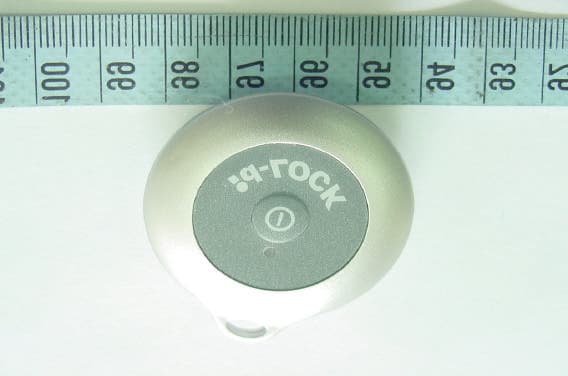
Click to zoom
Application Details
- Equipment Class
- DSC - Part 15 Security/Remote Control Transmitter
- Date of Grant
- Mar 03, 2004
- Application Purpose
- Original Equipment
- Date of Application
- Mar 03, 2004
- Equipment Note
- ID-Lock
- Frequency Range
- 315.00000000 - 315.00000000
- Company
- Kernel Technology Co., Ltd.
- Country
- Taiwan
Documents & Files
Document Text
Text extracted from the exhibit documents filed with the FCC. Open a document above to read the original.
Users Manual
id-LOCK An ideal wireless lock for your PC Table of Contents I. IMPORTANT NOTE FCC Information Declaration of Conformity II. QUICK INSTALLATION GUIDE III. INTRODUCTION How It Works System Requirement Specifications Package IV. HARDWARE Hardware Installation Hardware Removal V. SOFTWARE Software Installation Password Setting Product ID Validation Software Removal VI. USER GUIDE VII. FREQUENTLY ASKED QUESTIONS VIII. OPERATION NOTICE I. IMPORTANT NOTE To comply with the FCC RF exposure compliance requirements, no change to the antenna or the device is permitted. Any change to the antenna or the device could result in the device exceeding the RF exposure requirements and void user s authority to operate the device. FCC Information The equipment has been tested and found to comply with the limits for a Class B Digital Device, pursuant to part 15 of the FCC Rules. These limits are designed to provide reasonable protection against harmful interference in a residential installation. This equipment generates, uses and can radiate radio frequency energy and, if not installed and used in accordance with the instruction, may cause harmful interference to radio communication. However, there is no grantee that interference will not occur in a particular installation. If this equipment dose cause harmful interference to radio or television reception, which can be determined by turning the equipment off and on, the user is encouraged to try to correct the interference by one or more of the following measures: • Reorient or relocate the receiving antenna. • Increase the separation between the equipment and receiver. • Connect the equipment into an outlet on a circuit different from that to which the receiver is connected. • Consult the dealer or an experienced radio/TV technician for help. The user should not modify or change this equipment without written approval from the manufacturer. Modification could void authority to use this equipment. Declaration of Conformity Model No.: KL-007 FCC ID: RQNKL007 This device complies with part 15 of the FCC Rules. Operation is subject to the following two conditions: (1) This device may not cause harmful interference, and (2) This device must accept any interference received, including interference that may cause undesired operation. II. QUICK INSTALLATION GUIDE Follow Steps below to install your id-LOCK in minutes. Step 1 Before installing the software, make sure the id-LOCK receiver is properly inserted into USB port of your PC. Step 2 Insert enclosed CD-ROM into CD-ROM drive of your PC and follows the on-screen installation guide. Step 3 Key in the Password (Security Code) for backup in case of device failure or loss. It's advisable to keep this Password in mind. Step 4 Do the ID Validation procedure in order to associate your id-LOCK transmitter with the designated PC. Step 5 For detailed information or questions about id-LOCK , simply move your mouse to the id-LOCK taskbar icon and right click the mouse button, then select " User Manual " in the popup menu. III. INTRODUCTION How It Works • The id-LOCK is composed of a wireless transmitter and a receiver. Simply plug the receiver into USB port of your PC and carry the small, lower power consumption transmitter with you. • Your PC in use will be automatically locked when you are away from it for about 2 to 5 meters*. • Your PC automatically resumes normal operation when you return to the effective range. • When the PC is locked, you can also enter preset password to unlock it if your transmitter and/or receiver are not available. • One transmitter can be shared among several PC’s. * Environmental factors may adversely affect the signal range. System Requirement • IBM Compatible PC • Windows 98 SE, ME, 2000 or XP • Available USB Port • CD-ROM Drive Specifications • Operation Frequency: 315MHz / FCC; 434MHz / CE. • Power Supply: Transmitter - DC 3V/2.8mA; Receiver - DC 5V/20mA. • Size: Transmitter - 46 x 42 x 14mm; Receiver - 65 x 19 x 10mm • Weight: Transmitter (include CR-2032 battery) - 9g; Receiver - 9g Package • Transmitter Unit x 1 • Receiver Unit x 1 • 3V Battery (CR-2032) x 1 • CD-ROM x 1 • Lanyard x 1 • USB Extension Cable x 1 IV. HARDWARE Hardware Installation 1. Insert the id-LOCK receiver into USB port of your PC and the PC shall automatically detect if the hardware is properly installed. 2. If your PC fails to detect the receiver during software installation, following window will be displayed. Repeat above step and click Check Again or exit the setup program. 3. If the following window is displayed on the screen, click OK button to cancel the installation. 4. Double check to see if : • the USB port is fully functional and • the id-LOCK receiver is properly inserted into the USB port. • If you are going to use id-LOCK through a USB Hub connected to your PC, please insert id-LOCK receiver into USB port of your PC first during installation. Hardware Removal Simply unplug the id-LOCK receiver from the USB port. V. SOFTWARE Software Installation 1. Place enclosed CD-ROM that comes with the id-LOCK in the CD-ROM drive and your PC will automatically run the installation program. The screen will look like what shown below. Simply follow the on-screen instructions step by step to install the software. Click OK to start the installation. 2. When the software is being installed, the screen will look similar to the one below. 3. Click "OK" to confirm the installation is completed. Password Setting 1. After the software installation is completed, you will be asked to set the Password (Security Code). The id- LOCK software accommodates a password with up to 64 alpha-numeric characters. The alpha-numeric characters in password are case insensitive. Product ID Validation After you set up the Password successfully, an ID Validation procedure has to be completed in order to associate your id-LOCK transmitter with the designated PC before using the product. 1. Please make sure the id-LOCK transmitter is turned off, …
Text truncated - open the document above for the full version.
Cover Letter(s)
1 Mike Kuo From: S. S. Liou Sent: March032004Wednesday 8:32 PM To: Mike Kuo Cc: R00/ Subject: Re: Kernel Technology Co., Ltd., FCC ID:RQNKL007, AN04T3706 Dear Mike, The requirement in section 15.231(e) stating that "Intentional radiators may operate at a periodic rate exceeding that specified in paragraph (a) and may be employed for any type of operation, including operation prohibited in paragraph (a), ... In addition, devices operated under the provisions of this paragraph shall be provided with a means for automatically limiting operation so that the duration of each transmission shall not be greater than one second and the silent period between transmissions shall be at least 30 times the duration of the transmission but in no case less than 10 seconds." This device transmits pules train of 75ms each time and the silent period lasts 12 seconds which is longer than 75ms*30=2.25second and also the 10 seconds requirement. Best regards, ================================ S. S. Liou Engineer / EMC Dep. II ETC ----- Original Message ----- From: "Mike Kuo" <[email protected]> To: "ETC/Iris (E-mail)" "Liou, S. S. (E-mail)" Cc: "Will Yauo (E-mail)" Sent: Thursday, March 04, 2004 11:35 AM Subject: FW: Kernel Technology Co., Ltd., FCC ID:RQNKL007, AN04T3706 > > > -----Original Message----- > From: CERTADM > Sent: Wednesday, March 03, 2004 7:35 PM > To: Mike Kuo > Subject: Kernel Technology Co., Ltd., FCC ID:RQNKL007, AN04T3706 > > > Notice_content > ------------- > Question #1: Based upon the device description in the user manual. Once it > is powered on, it will transmit continuously to the receiver. Only when the > transmitter is away for 2-3 meter, the receiver can not receive the signal, > then receiver will lock the PC. With this understanding in mind, the > transmitter is transmitting continuously which does not comply with 15.231 > definition as periodical transmitter. Please provide technical > justification to demonstrate that this device is periodical transmitter. > > Best Regards > > Mike Kuo > The items indicated above must be submitted before processing can continue > on the above referenced application. Failure to provide the requested 2 > information within 30 days of the original e-mail date may result in > application dismissal and forfeiture of the filing fee. Also, please note > that partial responses increase processing time and should not be submitted. > Any questions about the content of this correspondence should be directed to > the e-mail address listed below the name of the sender.
External Photos
ETC Report No.:ET92R-12-120-06 FCC ID.: RQNKL007 Rev. No 1.0 CONSTRUCTED PHOTOS of EUT Top View of EUT Top View of EUT
ID Label/Location Info
id-LOCKFCC This statement will be placed in User Manual: This device complies with part 15 of the FCC Rules. Operation is subject to the following two conditions: (1) This device may not cause harmful interference, and (2) This device must accept any interference received, including interference that may cause undesired operation. FCC ID: RQNKL007 15mm 3mm On the back of id-LOCK transmitter
Internal Photos
ETC Report No.:ET92R-12-120-06 FCC ID.: RQNKL007 Rev. No 1.0 CONSTRUCTED PHOTOS of EUT Internal View of EUT ETC Report No.:ET92R-12-120-06 FCC ID.: RQNKL007 Rev. No 1.0 CONSTRUCTED PHOTOS of EUT Component View of Main PCB Solder View of Main PCB
Operational Description
INTRODUCTION How It Works †• The id-LOCK is composed of a wireless transmitter and a receiver. Simply plug the receiver into USB port of your PC and carry the small, lower power consumption transmitter with you. †• Your PC in use will be automatically locked when you are away from it for about 2 to 5 meters*. †• Your PC automatically resumes normal operation when you return to the effective range. †• When the PC is locked, you can also enter preset password to unlock it if your transmitter and/or receiver are not available. †• One transmitter can be shared among several PC’s. * Environmental factors may adversely affect the signal range. System Requirement †• IBM Compatible PC †• Windows 98 SE, ME, 2000 or XP †• Available USB Port †• CD-ROM Drive Specifications †• Operation Frequency: 315MHz / FCC †• Power Supply: Transmitter - DC 3V/2.8mA; Receiver - DC 5V/20mA. †• Size: Transmitter - 46 x 42 x 14mm; Receiver - 65 x 19 x 10mm †• Weight: Transmitter (include CR-2032 battery) - 9g; Receiver - 9g
Test Report
Rev. No 1.0 FCC Part 15 EMI TEST REPORT of E.U.T. : Id-LOCK FCC ID. : RQNKL007 MODEL : KL-007 Working Frequency : 315 MHz for APPLICANT : Kernel Technology Co., Ltd. ADDRESS : No. 8, Lane 76, Ta-Chin St., Sec. 1, Taichung, 402, Taiwan, R.O.C. Test Performed by ELECTRONICS TESTING CENTER, TAIWAN NO. 34, LIN 5, DING FU TSUN, LINKOU HSIANG TAIPEI HSIEN, TAIWAN, R.O.C. Tel:(02)26023052 Fax:(02)26010910 http://www.etc.org.tw ; e-mail : [email protected] Report Number : ET92R-12-120-06 ETC Report No.:ET92R-12-120-06 FCC ID.: RQNKL007 Rev. No 1.0 Table of Contents Page 1. GENERAL INFORMATION.....................................................................................................................................................1 1.1 PRODUCT DESCRIPTION...........................................................................................................................................................1 1.2 CHARACTERISTICS OF DEVICE:...............................................................................................................................................1 1.3 TEST METHODOLOGY..............................................................................................................................................................1 1.4 TEST FACILITY..........................................................................................................................................................................1 2. DEFINITION AND LIMITS.......................................................................................................................................................2 2.1 DEFINITION................................................................................................................................................................................2 2.2 RESTRICTED BANDS OF OPERATION.....................................................................................................................................2 2.3 LIMITATION...............................................................................................................................................................................2 2.4 LABELING REQUIREMENT.......................................................................................................................................................4 2.5 USER INFORMATION.................................................................................................................................................................4 3 SYSTEM TEST CONFIGURATION.........................................................................................................................................5 3.1 JUSTIFICATION..........................................................................................................................................................................5 3.2 DEVICES FOR TESTED SYSTEM...............................................................................................................................................5 4. RADIATED EMISSION MEASUREMENT.............................................................................................................................6 4.1 APPLICABLE STANDARD.........................................................................................................................................................6 4.2 MEASUREMENT PROCEDURE..................................................................................................................................................6 4.3 TEST DATA.................................................................................................................................................................................8 4.3.1 Tx Fundamental and Harmonics..................................................................................................................................8 4.3.2 Other Emissions...............................................................................................................................................................9 4.4 FIELD STRENGTH CALCULATION........................................................................................................................................10 4.5 ACTIVATE TIME......................................................................................................................................................................10 4.6 CALCULATION OF DUTY FACTOR.......................................................................................................................................10 4.7 RADIATED TEST EQUIPMENT...............................................................................................................................................11 4.8 MEASURING INSTRUMENT SETUP.......................................................................................................................................11 4.9 RADIATED MEASUREMENT PHOTOS...................................................................................................................................12 5. BANDWIDTH OF EMISSION...............................................................................................................................................13 5.1 APPLICABLE STANDARD PLOT GRAPHIC OF BANDWIDTH............................................................................................13 5.2 BANDWIDTH TEST EQUIPMENT...........................................................................................................................................13 5.3 PLOT GRAPHIC OF BANDWIDTH..........................................................................................................................................13 6. CONDUCTED EMISSION MEASUREMENT......................................................................................................................14 6.1 DESCRIPTION..............…
Text truncated - open the document above for the full version.
Test Setup Photos
ETC Report No.:ET92R-12-120-06 FCC ID.: RQNKL007 Rev. No 1.0 Radiated Measurement Photos
Contact Information
Applicant
Kevin Lin(Project Manager)
Test Firm
Electronics Testing Center, TaiwanWin-Po Tsai
Technical Specifications
| # | Rule Parts | Frequency Range | Power Output |
|---|---|---|---|
| 1 | 15.231(e) | 315 MHz - 315 MHz | - |