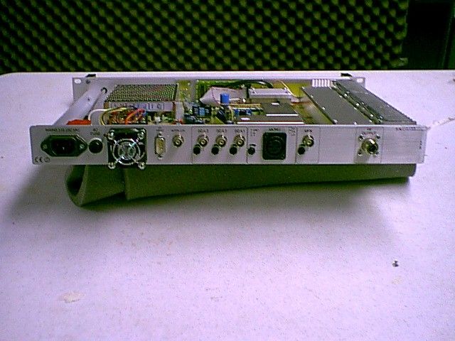
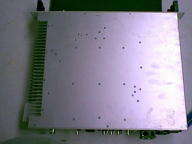
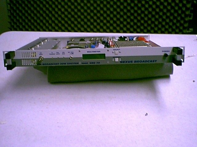
RR4NBE20FM Exciter for Broadcast Use
Nexus Broadcast Products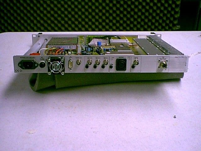
Click to zoom
Application Details
- Equipment Class
- TBC - Licensed Broadcast Station Transmitter
- Date of Grant
- Apr 13, 2004
- Application Purpose
- Original Equipment
- Date of Application
- Apr 13, 2004
- Equipment Note
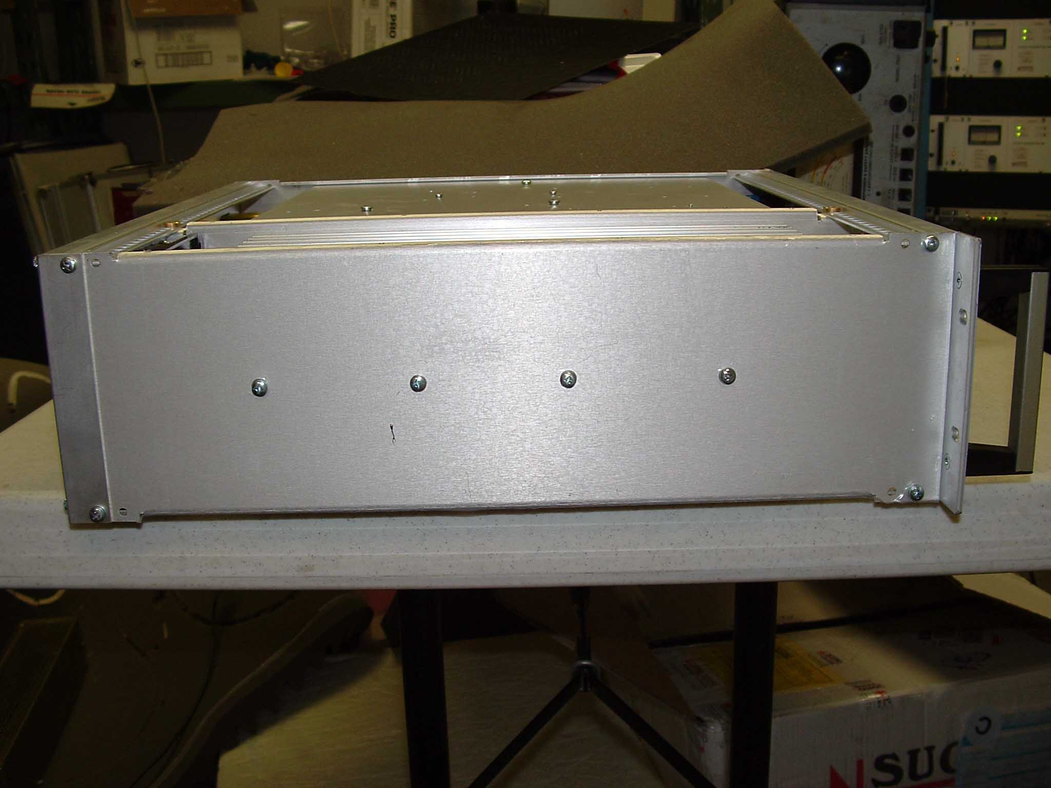
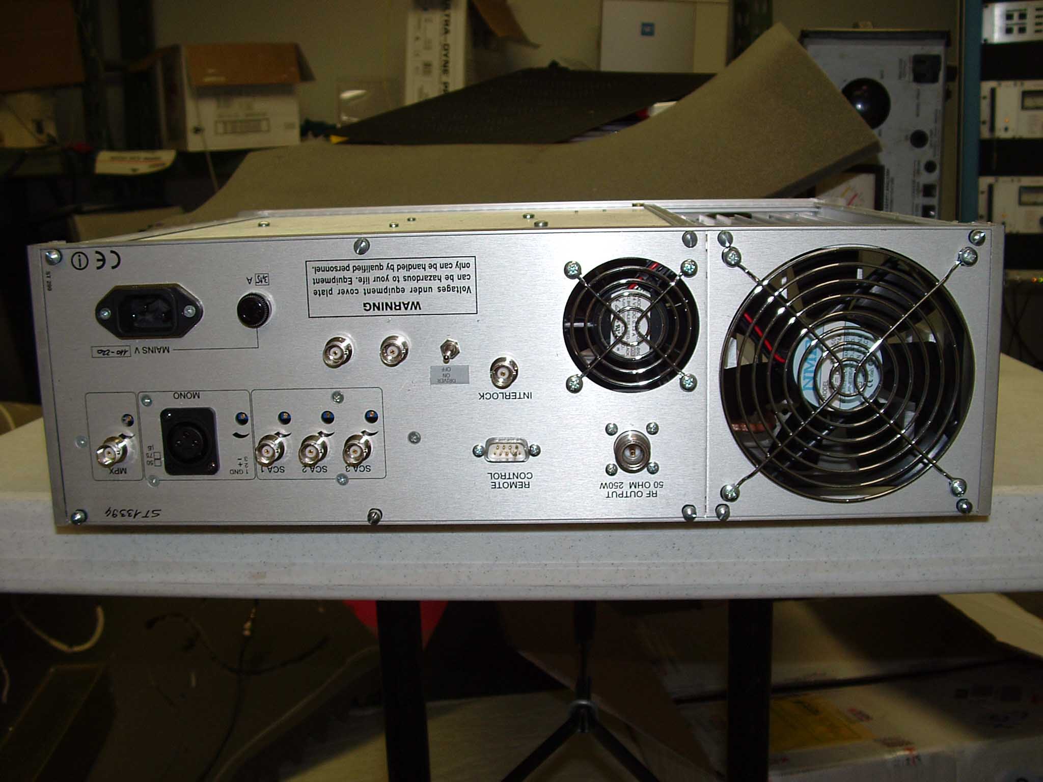
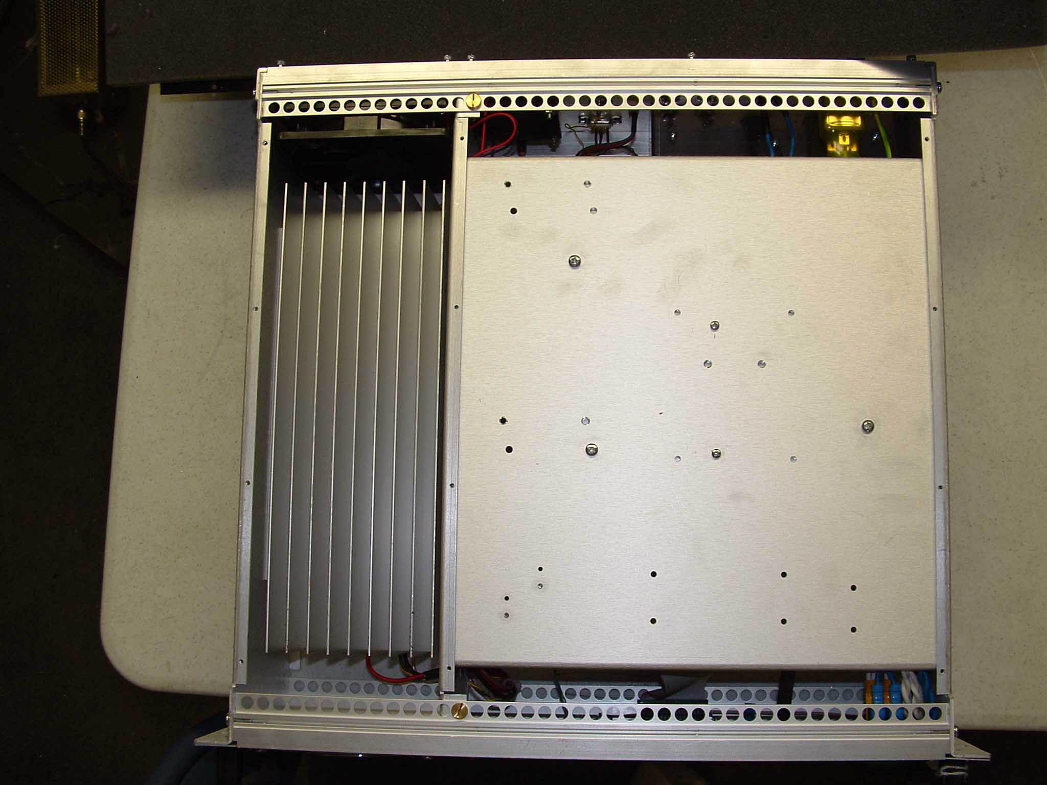
- FM Exciter for Broadcast Use
- Frequency Range
- 88.10000000 - 107.90000000
- Company
- Nexus Broadcast Products
- Country
- United States
Documents & Files

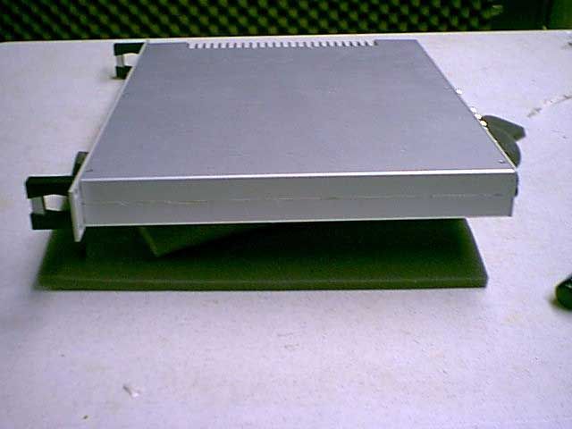
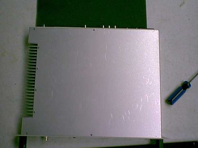
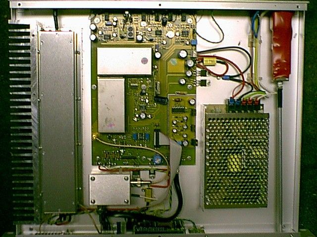
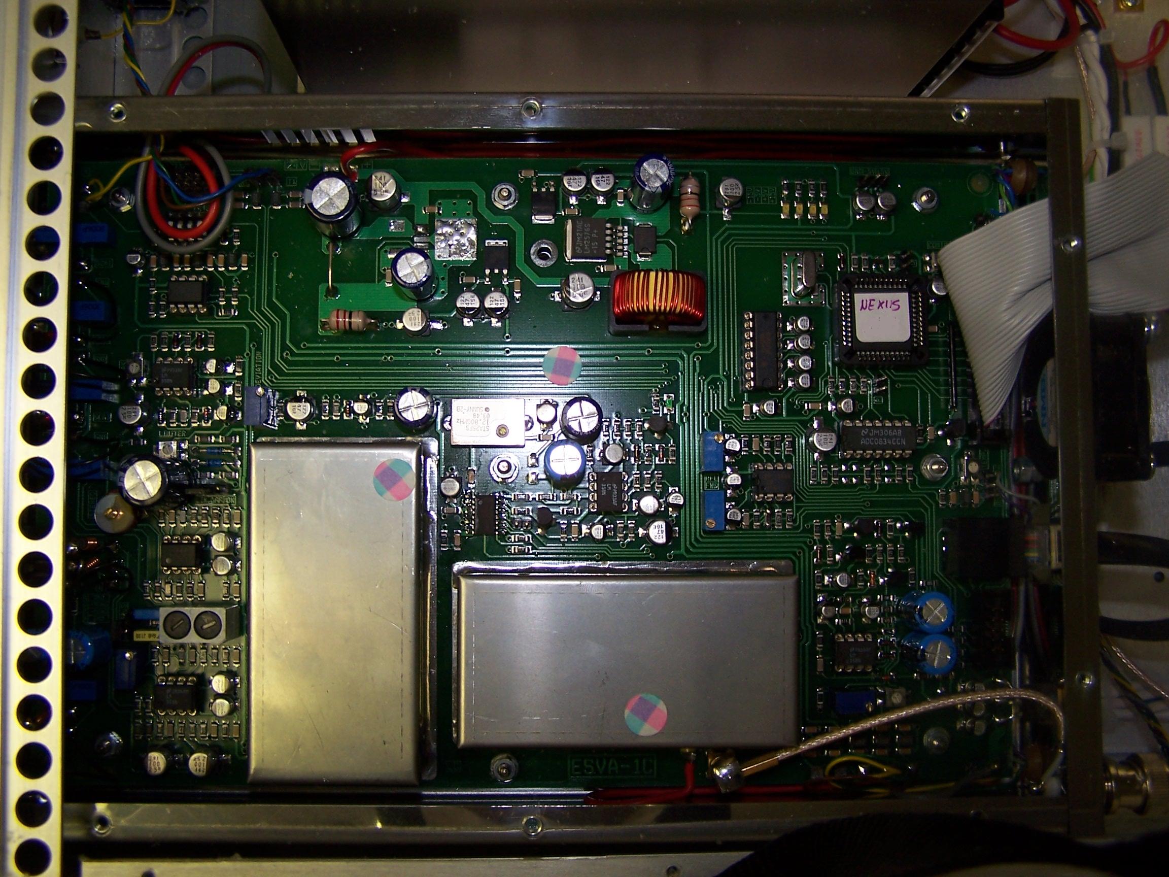
Document Text
Text extracted from the exhibit documents filed with the FCC. Open a document above to read the original.
Users Manual
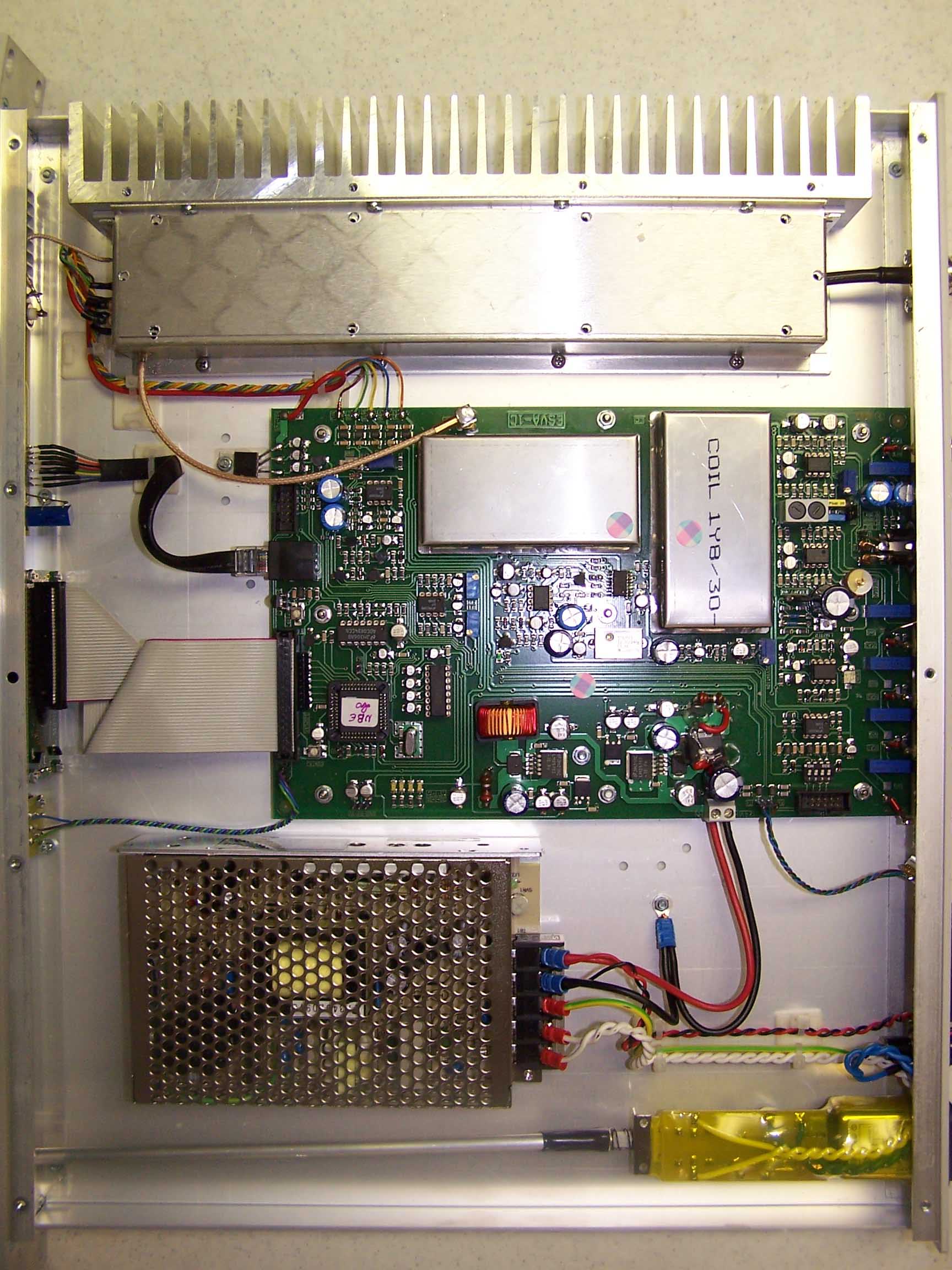
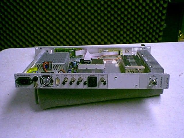
NEXUS BROADCAST PRODUCTS Please observe safety precautions when handling this unit. This equipment contains dangerous currents and high voltages. This manual is written as a general guide for those having previous knowledge and experience with this kind of equipment. It is not intended to contain a complete statement of all safety warnings which should be observed by personnel in using this or other electronic equipment. Nexus Broadcast is not responsible for injury or damage resulting from improper procedures or practices by untrained/unqualified personnel in the handling of this unit. Please observe all local codes and fire protection standards in the operations of this unit. CAUTION: always disconnect power before opening covers or removing any part of this unit. Use appropriate grounding procedures to short out capacitors and high voltage points before servicing. Any damage to the goods must be reported to the carrier in writing on the shipment receipt. Any discrepancy or damage discovered subsequent to delivery, shall be reported to Nexus Broadcast within seven (7) days from its receipt. Nexus Broadcast extends to the original end-user purchaser all original manufacturers warranties which are transferable and all claims are to be made directly to Nexus Broadcast per indicated procedures. All manufacturers warranties will be supported by Nexus Broadcast to ensure precise and speedy service where possible. Nexus Broadcast shall not be liable for any damage of whatsoever nature, arising out of or in connection whit the product or its use thereof. NEXUS BROADCAST PRODUCTS Nexus Broadcast's warranty shall not include: !Re-shipment of the unit to Nexus Broadcast for repair purposes; !Any unauthorized repair/modification; !Incidental/consequential damages as a result of any defect; !Nominal non-incidental defects; !Re-shipment costs or insurance of the unit or replacement units/parts. Warranty shall come into force from invoice date and for the period of the manufactures warranty. To claim your rights under this warranty: Contact the dealer or distributor where you purchased the unit. Describe the problem and ask if he has an easy solution. Dealers and Distributors are supplied with all the information about problems that may occur and usually they can repair the unit quicker than what the manufacturer could do. Very often installing errors are discovered by dealers. If your dealer cannot help you, contact Nexus Broadcast and explain the problem. If it is decided to return the unit to the factory, Nexus Broadcast will mail you a regular authorization with all the necessary instructions to send back the goods. When you receive the authorization, you can return the unit. Pack it carefully for the shipment, preferably using the original packing and seal the package perfectly. The customer always assumes the risks of loss (i.e., Nexus Broadcast is never responsible for damage or loss), until the package reaches Nexus Broadcast premises. For this reason, we suggest you to insure the goods for the whole value. NEXUS BROADCAST PRODUCTS (PREPAID) to the address specified by Nexus Broadcast's service manager on the authorization. DO NOT RETURN UNITS WITHOUT OUR AUTHORIZATION AS THEY WILL BE REFUSED. Be sure to enclose a written technical report where mention all the problems found and a copy of your original invoice establishing the starting date of the warranty. Replacement and warranty parts may be order from the following address. Be sure to include the equipment model and serial number as well as part description and part number. Nexus Broadcast P.O. Box 433 500 East Main #20 Mount Vernon, TX 75457 Tel. 903-524-4166 Fax 903-524-2260 Email:[email protected] NEXUS BROADCAST PRODUCTS The model NBE-25 is an FM broadcast exciter transmitter based upon a totally solid state design, using the latest modern and reliable techniques on the market. The main characteristics of the equipment are: !Output power adjustable from frontal panel between 0 to 20 Watts, with automatic power control, the output power does not vary with change of temperature. !Protection for excessive reflected power: if it goes over 5 W the incident power is reduced to ensure the reflection level does not exceed 5 W; !The power stage allows open circuit and short circuit operation of the output, due to use of an MRF173 MOSFET that has a maximum RF power of 80 W; !The control-interface unit is an microprocessor which by using the front panel push buttons can program the VCO frequency from 87.50 MHz to 108.00 Mhz. In order to change the frequency a password is required. This exciter is built into one 19" rack space, comprising a number of interconnections between modules mounted internally on the bottom of the apparatus, for easy removal and replacement. NEXUS BROADCAST PRODUCTSNEXUS BROADCAST PRODUCTS NEXUS BROADCAST PRODUCTS Connected a 50ohm load or 50 ohm antenna to the RF output, connect the equipment into a mains supply (100-r240 VAC) with earth point. The equipment is factory pre-set to 0 W. Switch ON the power switch and the yellow V POWER led will light. The Display will show: WAIT SELECT SETTING After 3 seconds the green PLL LOCK led will light and the Display will show an increasing bar, after a further 5 seconds the green ON AIR led will light and there will be output power. WAIT SELECT SETTING At this point the Display will show the next parameter: Level Modulation (MOD > Forward Power (FRW 5.0W); Reflected Power (RFL 0.4W). MOD > FRW5.0W RFL 0.4W SELECT SETTING The default frequency is 98.000 MHz. To display the frequency push the SETTING key. In order to display the parameter push the SELECT key. NEXUS BROADCAST PRODUCTS NEXUS BROADCAST PRODUCTS NEXUS BROADCAST PRODUCTS NEXUS BROADCAST PRODUCTS NEXUS BROADCAST
Users Manual
Before being shipped, each apparatus must pass a 48 hour quality control test. Most failures can be detected bv means of intermittent operation during this test. Nevertheless, a component may fail, but only after a longer period of operation. NEXUS BROADCAST Warrants that all products of its own manufacture conform to NEXUS BROADCAST specifications and are free from defects in material and workmanship when used under normal operating conditions and within the service conditions for which they were furnished. The obligation of NEXUS BROADCAST hereunder shall expire one (1) year after delivery and is limited to repairing, or at its option, replacing without charge, any such product which in NEXUS BROADCAST'S sole opinion proves to be defective within the scope of this warranty. This is NEXUS BROADCAST'S sole warranty with respect to the products delivered hereunder. No statement, representation agreement or understanding, oral or written, made by an agent, distributor, representative or employee of, which is not contained in this warranty will be binding upon NEXUS BROADCAST, unless made in writing and executed by an NEXUS BROADCAST makes no other warranty of any kind whatsoever, expressed or implied, and all implied warranties of merchantability and fitness for a particular use which exceed the above stated obligation are hereby disclaimed by NEXUS BROADCAST and excluded from this agreement. Under no circumstances shall NEXUS BROADCAST be liable to Buyer, in contract or in tort, for any special, indirect, incidental or consequential damages, losses or delays however caused. SHIPPING TO MANUFACTURER FOR REPAIR OR ADJUSTMENT NEXUS BROADCAST must be notified in writing of the defect or nonconformity within the warranty period and the affected product returned to NEXUS BROADCAST'S factory or to an authorized service center within thirty (30) days after discovery of such defect or nonconformity. Shipment shall not be made without prior authorization by NEXUS BROADCAST. All shipments to NEXUS BROADCAST, should be sent prepaid. The instrument should be shipped in the original packing carton; or if it is not available, use any suitable container that is rigid and of adequate size. If a substitute container is used, the instrument should be wrapped in paper and surrounded with at least four inches of excelsior or similar shock-absorbing material.
Block Diagram
VCO AUDIO INPUT RF DRVER RF AMPLIFIER PLL LIMITER TCXO 12.8 MHz LPF DIRECTIONAL COUPLER POWER SWITCHING SUPPLY SIGNAL INTERFACE MICROCONTROLLER DISPLAY N E X U S MPX MONO SCA ADJ RS232 VDCVAC RF OUTPUT MHz 98.000 Mod. NBE20 1.0 FUNCTIONAL SCHEMATIC B 11Tuesday, December 23, 2003 Title SizeDocument NumberRev Date:Sheetof NEXUS BROADCASTNEXUS BROADCAST
Operational Description
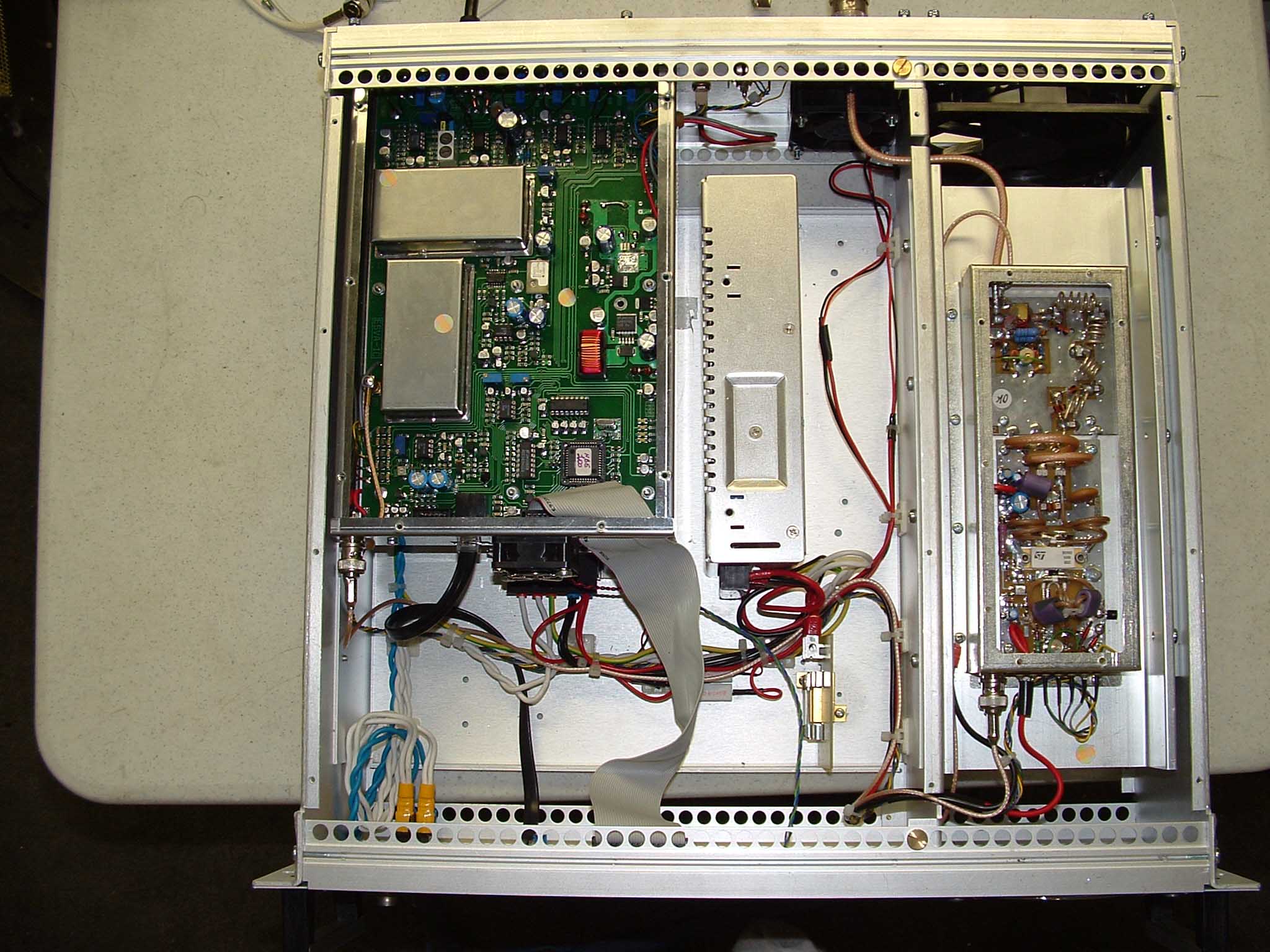
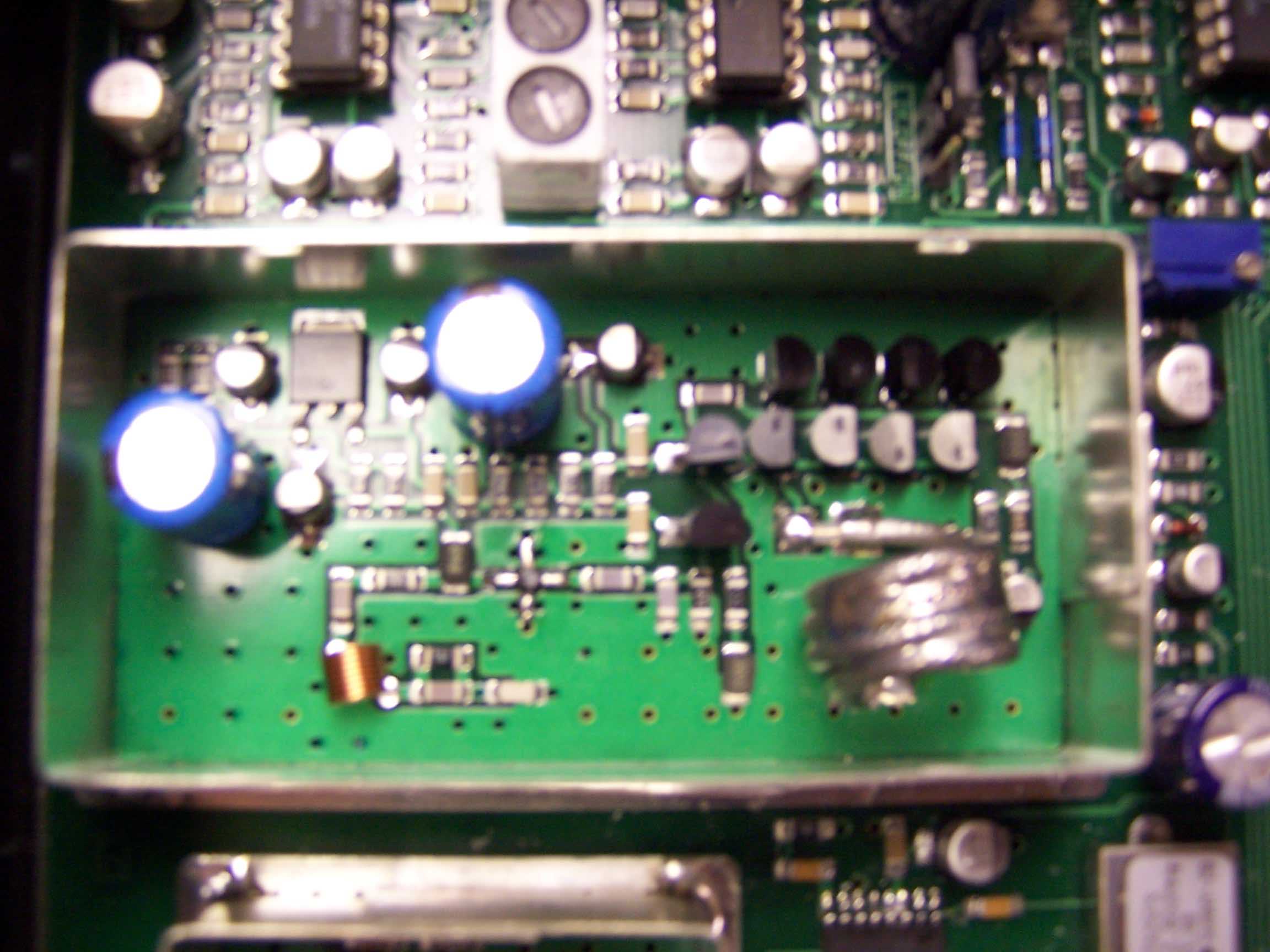
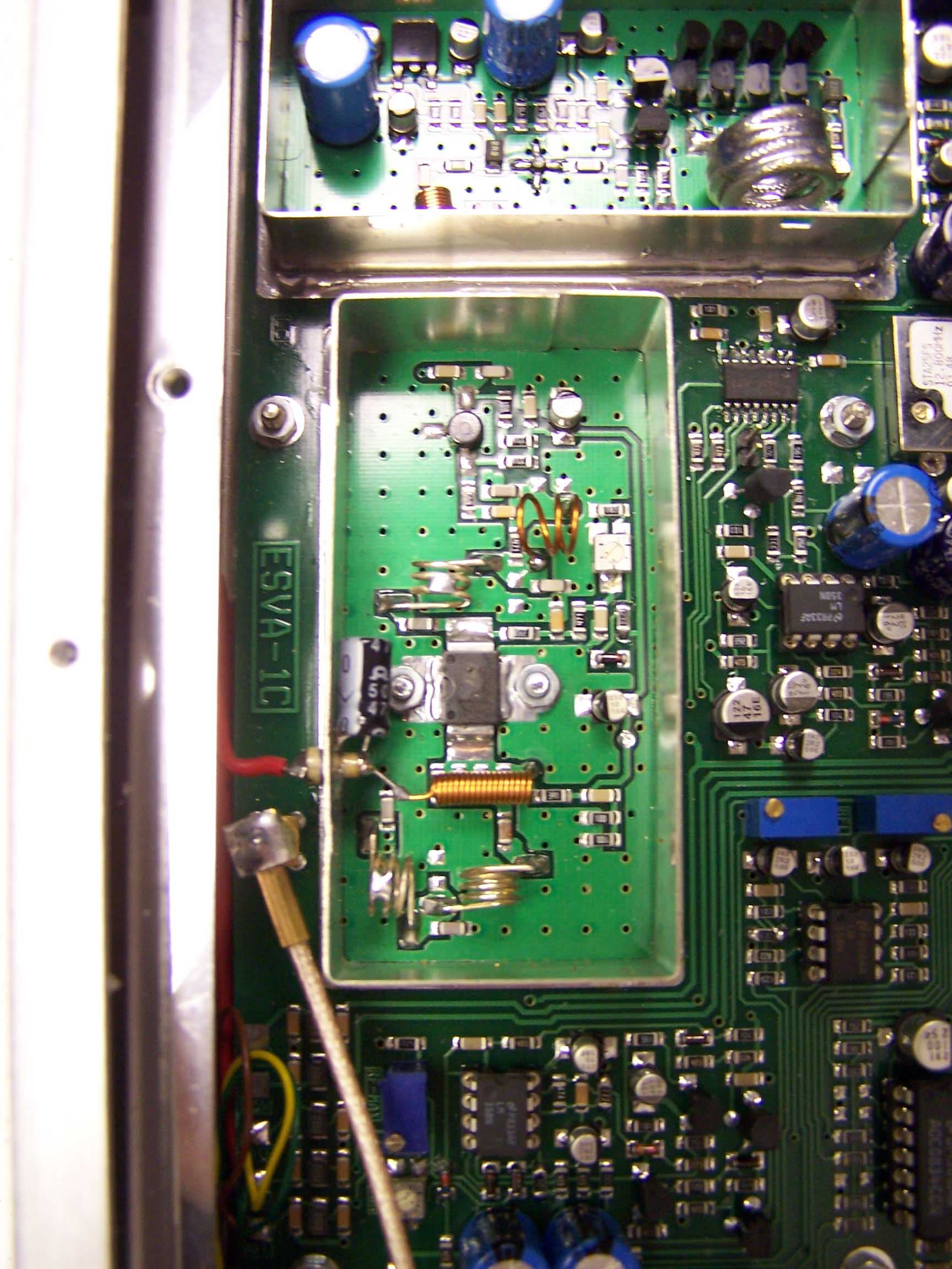
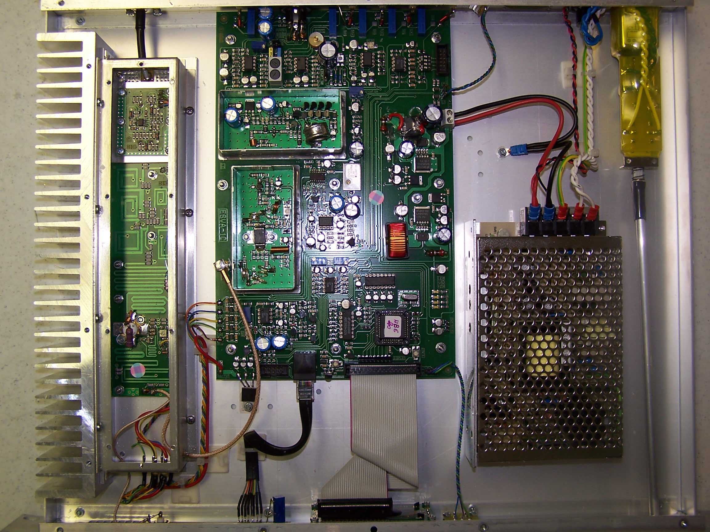
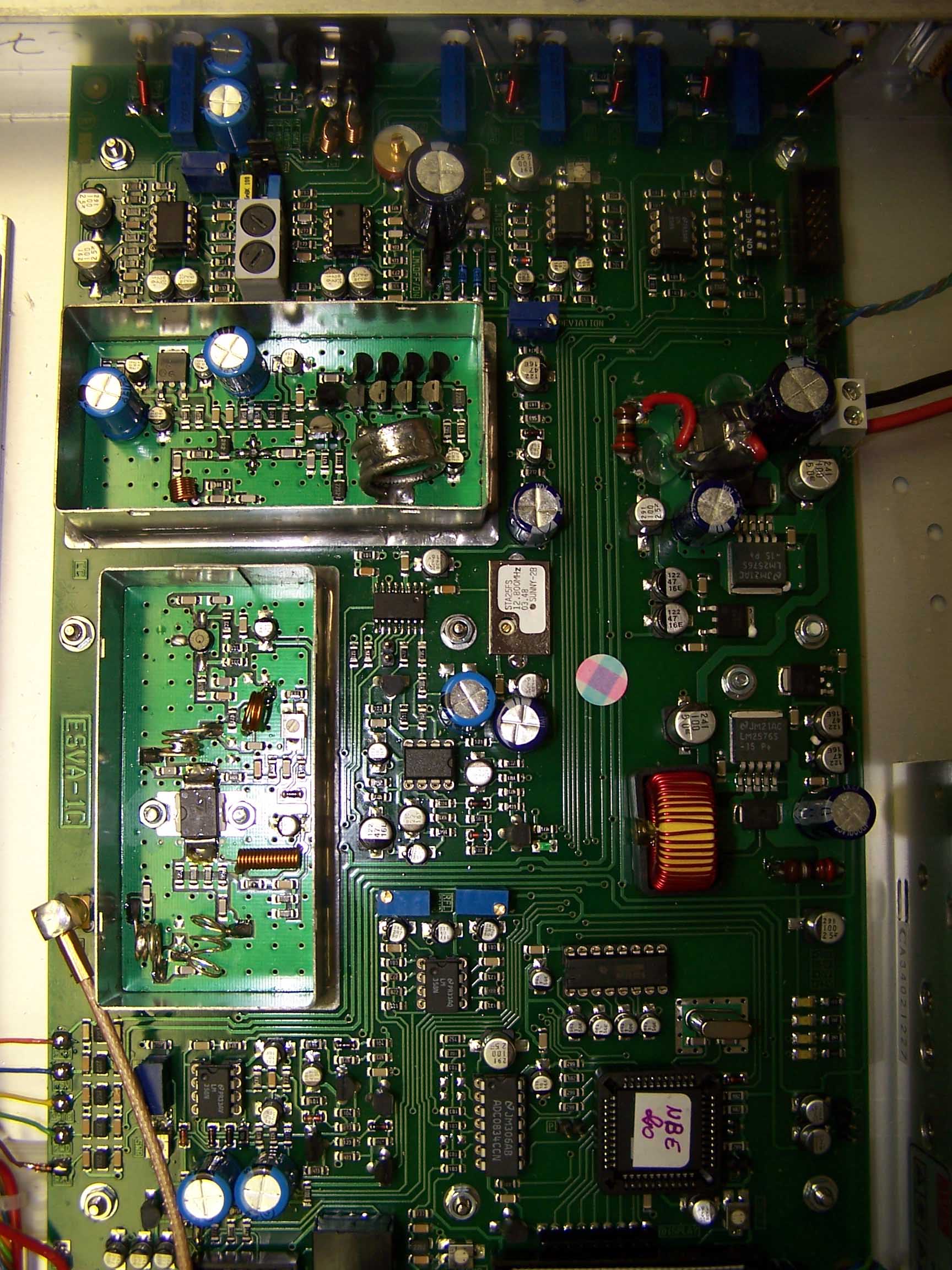
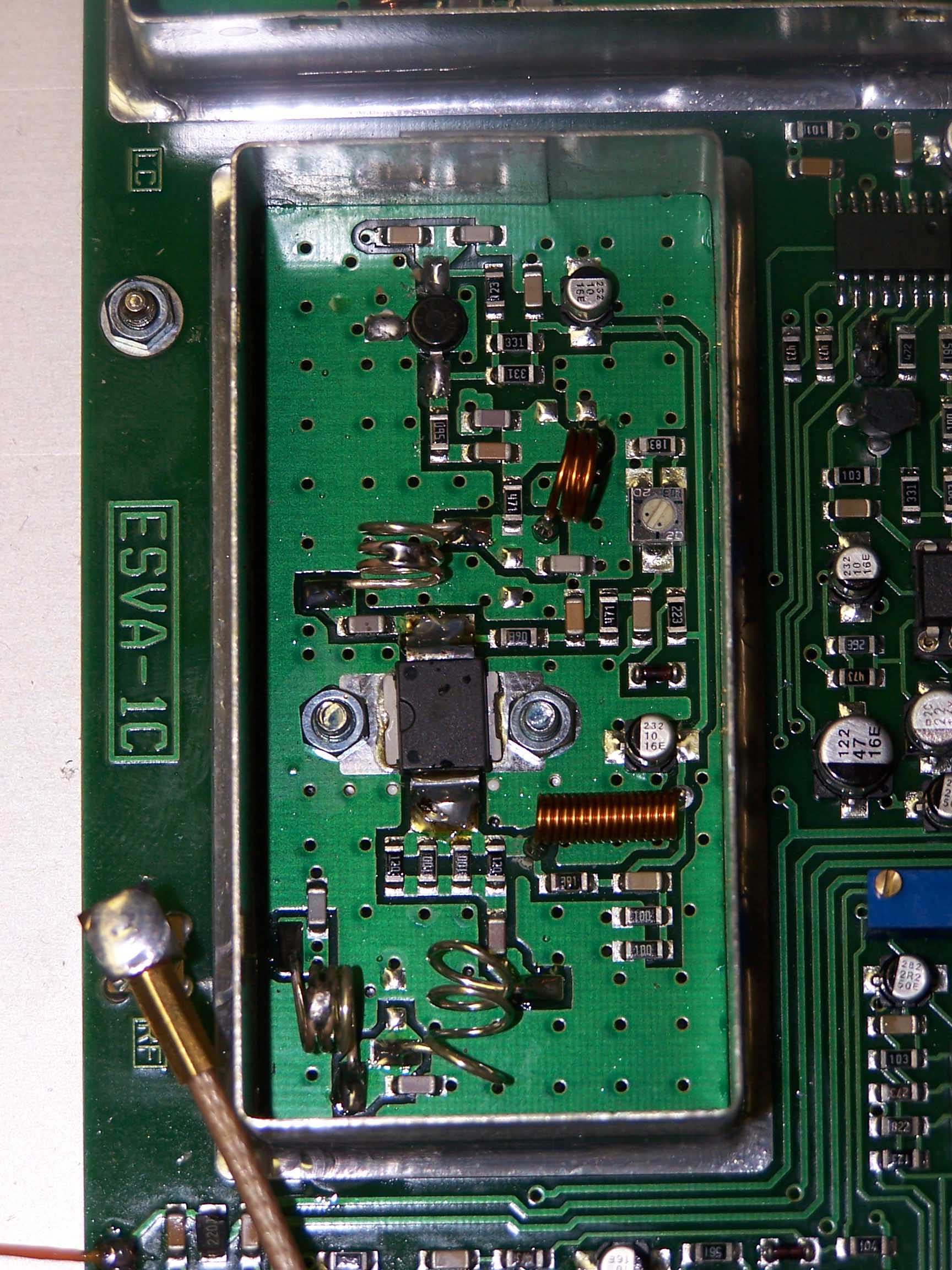
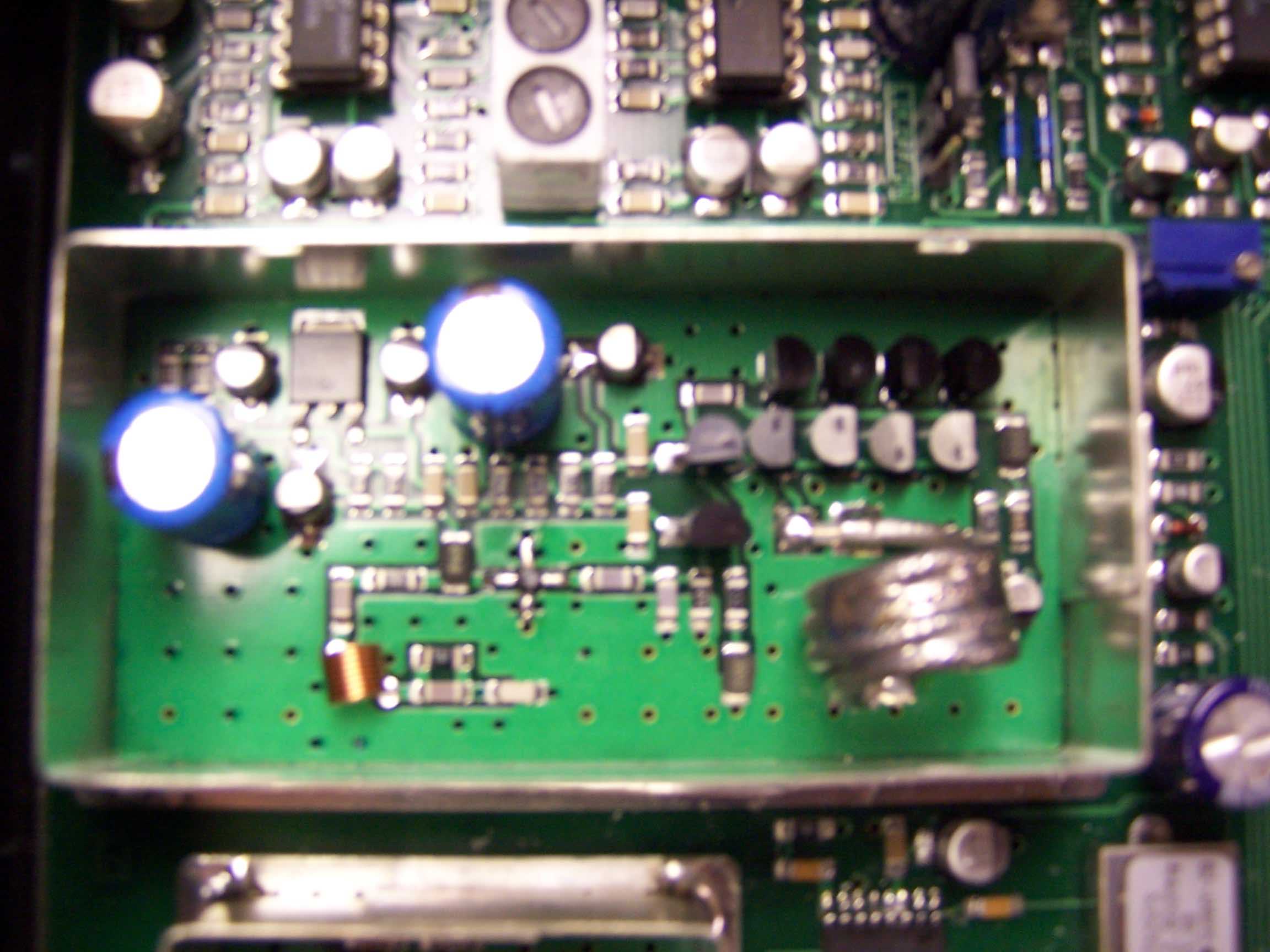
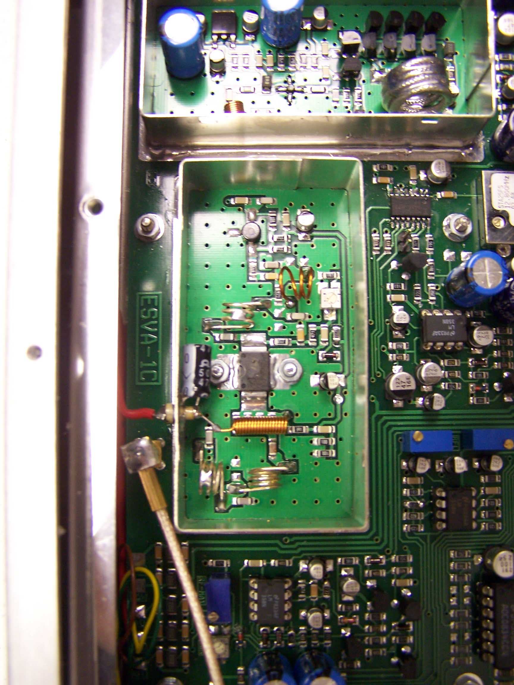
FM TRANSMITTER NBE20 Technical features of RF driver section and RF final power stage The driver stage is placed in the main board and it is composed by two active devices, the first one is a BFR96S working on AB class that has an output of 0,2W, then the true driving device is an LDMOS mod. PD55003 by ST Microelectronics, and below the technical working specifications: Vcc 15 V Idq 6 mA IDC at Full Power 610 mA Power Gain >13 dB Output Power > 2.5W Frequency range87.5 – 108 MHz Polarization B class The signal, after going out from the driver, goes to the final power stage made by a Mos-Fet mod. BLF245 by Philips and then to a low pass filter made by printed circuit inductances in order to be very stable during the time, then the signal passes trough a directional coupler for sampling the forward and reflected RF power. Below the technical specifications of the power stage: Vcc 24 V Idq 2.6 mA IDC at Full Power 1.7 A Power Gain >9 dB Output Power > 20W Frequency range 87.5 – 108 MHz Polarization B class Below the low pass filter specifications: Insertion Loss @ 175 MHz > 60dB In band return loss < - 30dB Here below we can see a photo of the NBE 20 RF module amplifier
Operational Description
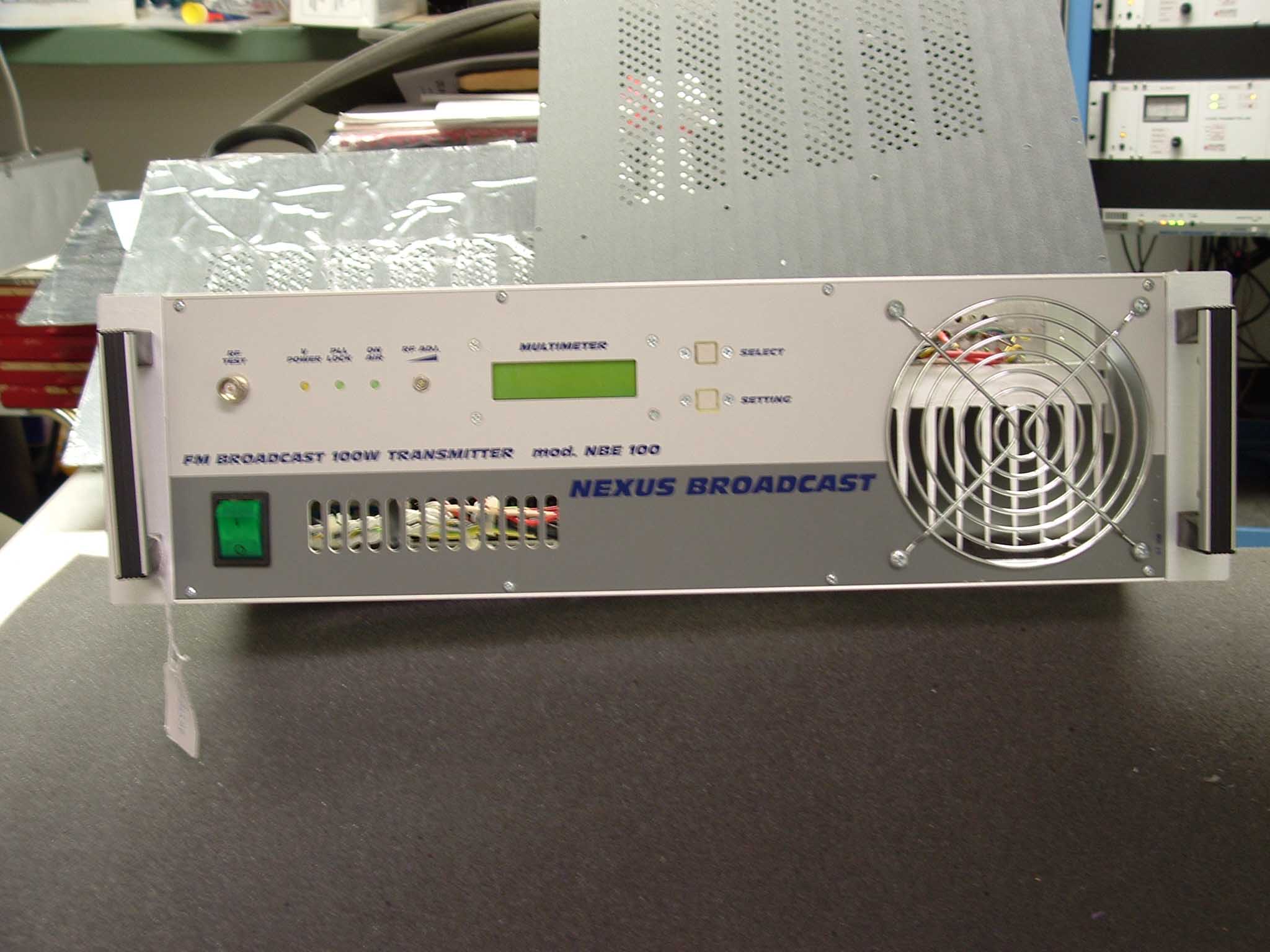
FM TRANSMITTER NBE100 Technical features of RF driver section and RF final power stage The driver stage is placed in the main board and it is composed by two active devices, the first one is a BFR96S working on AB class that has an output of 0,2W, then the true driving device is an LDMOS mod. PD55003 by ST Microelectronics, and below the technical working specifications: Vcc 15 V Idq 25 mA IDC at Full Power 850 mA Power Gain >13 dB Output Power > 4W Frequency range87.5 – 108 MHz Polarization B class The signal, after going out from the driver, goes to the final power stage made by a double Mos-Fet mod. SD2932 by ST and then to a low pass filter and a notch circuit tuned on 176MHz, after then the signal passes trough a directional coupler for sampling the forward and reflected RF power. Below the technical specifications of the power stage: Vcc 46 V Idq 40 mA IDC at Full Power 5.5 A Power Gain >14 dB Output Power > 100W Frequency range 87.5 – 108 MHz Polarization B class Below the low pass filter specifications: In band insertion loss < 0.3dB Insertion Loss @ 175 MHz > 60dB In band return loss < - 30dB Here below we can see a photo of the NBE 100 RF module amplifier
Operational Description
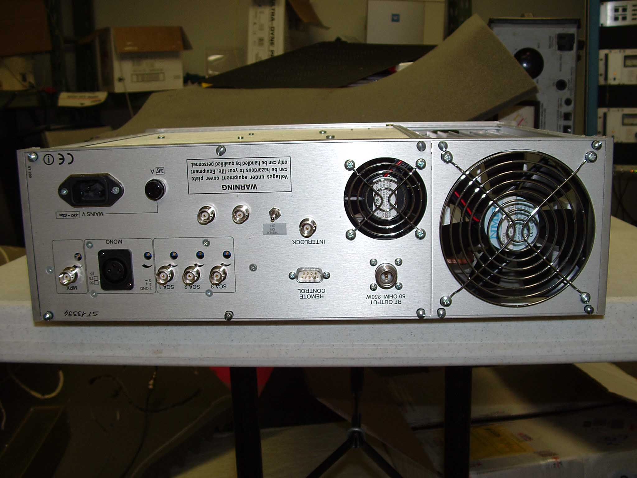
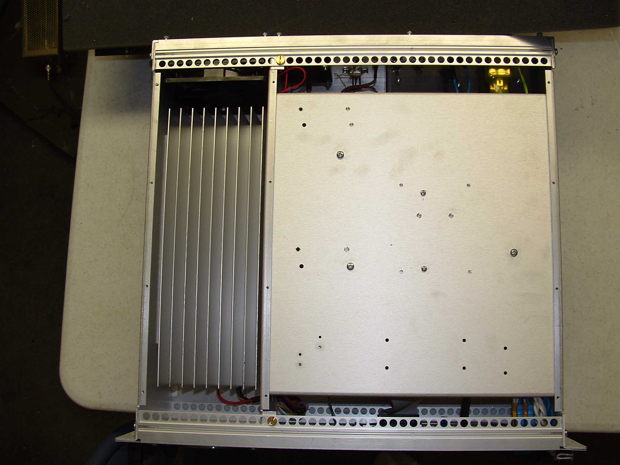
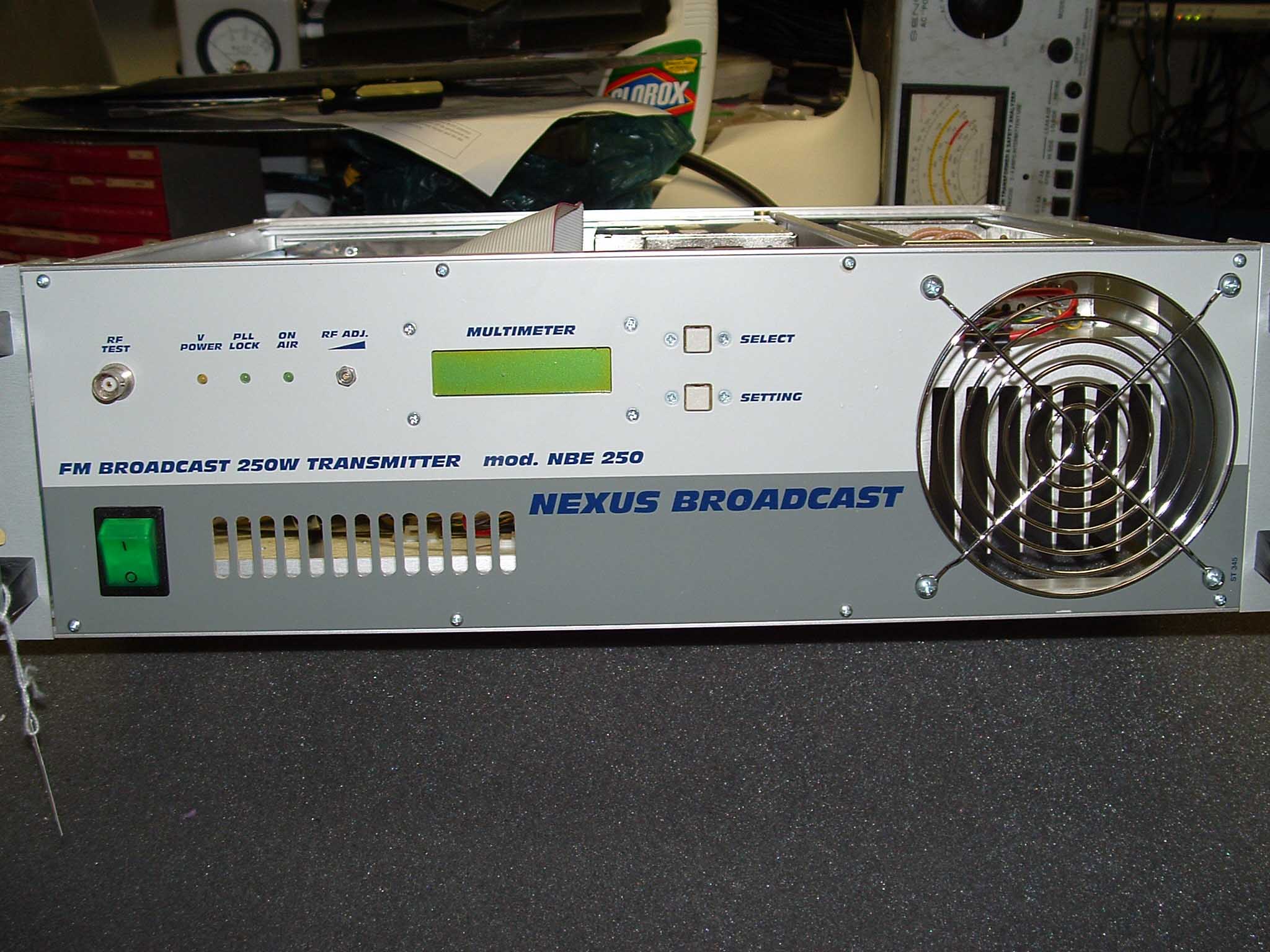
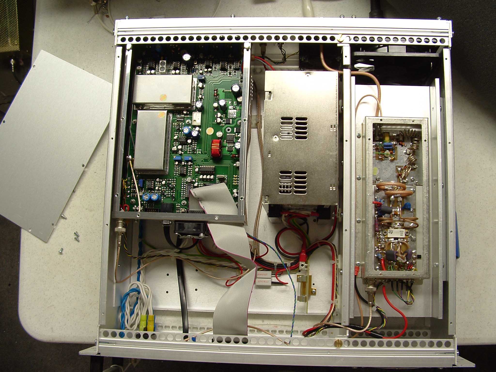
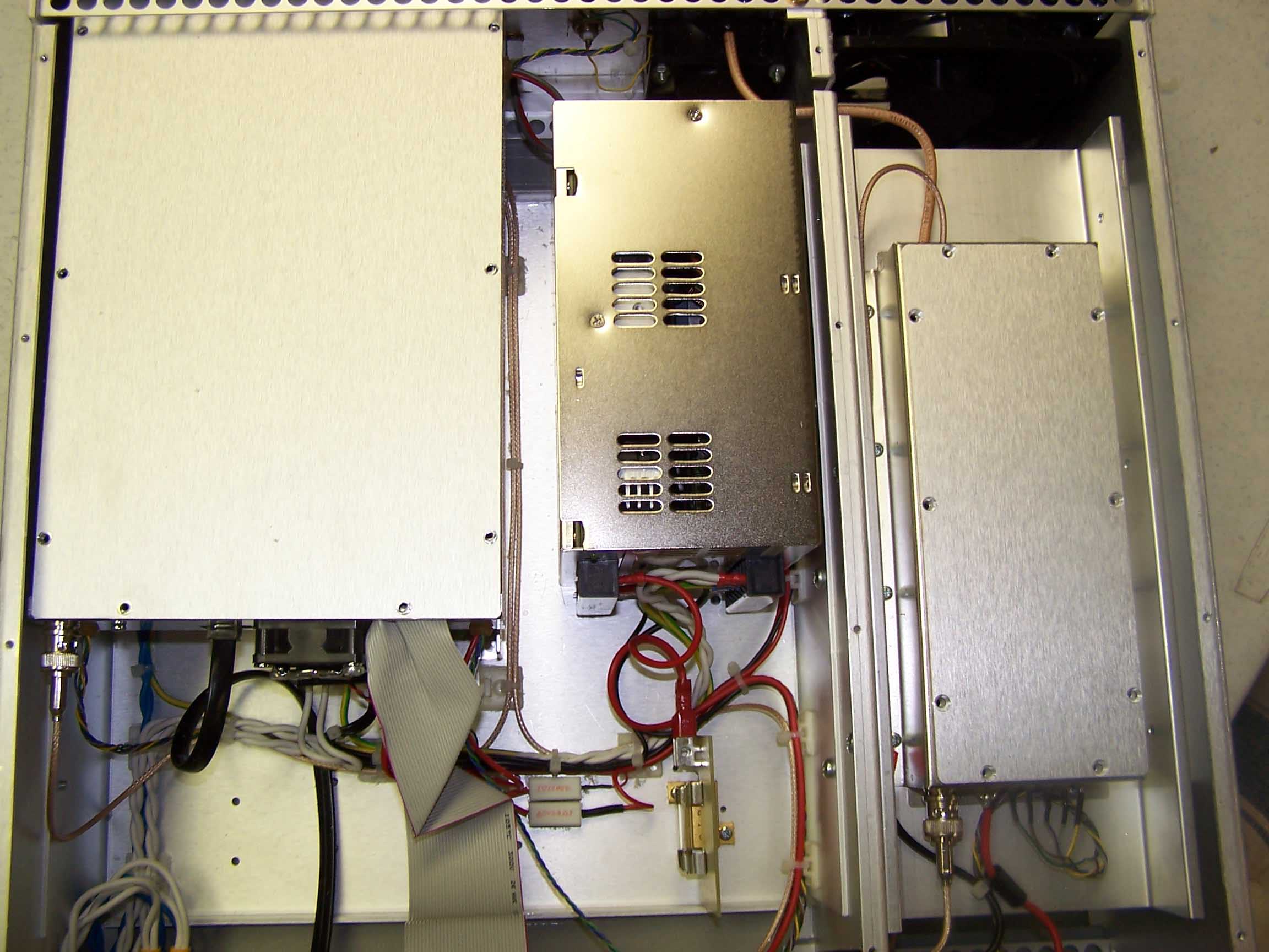
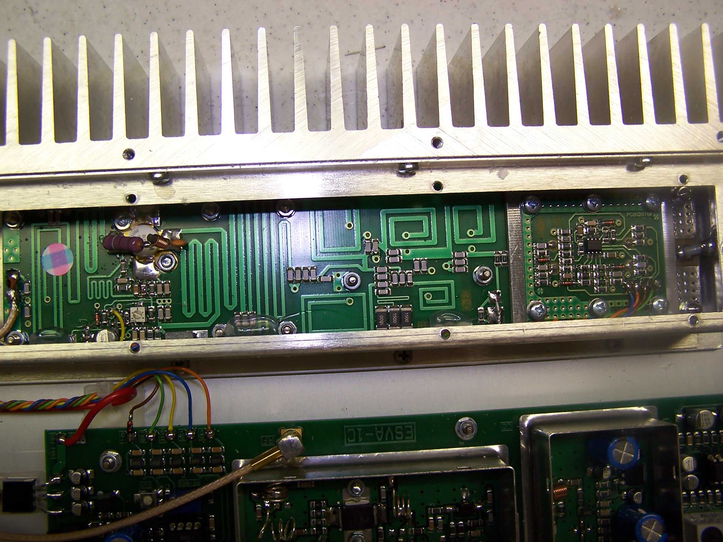
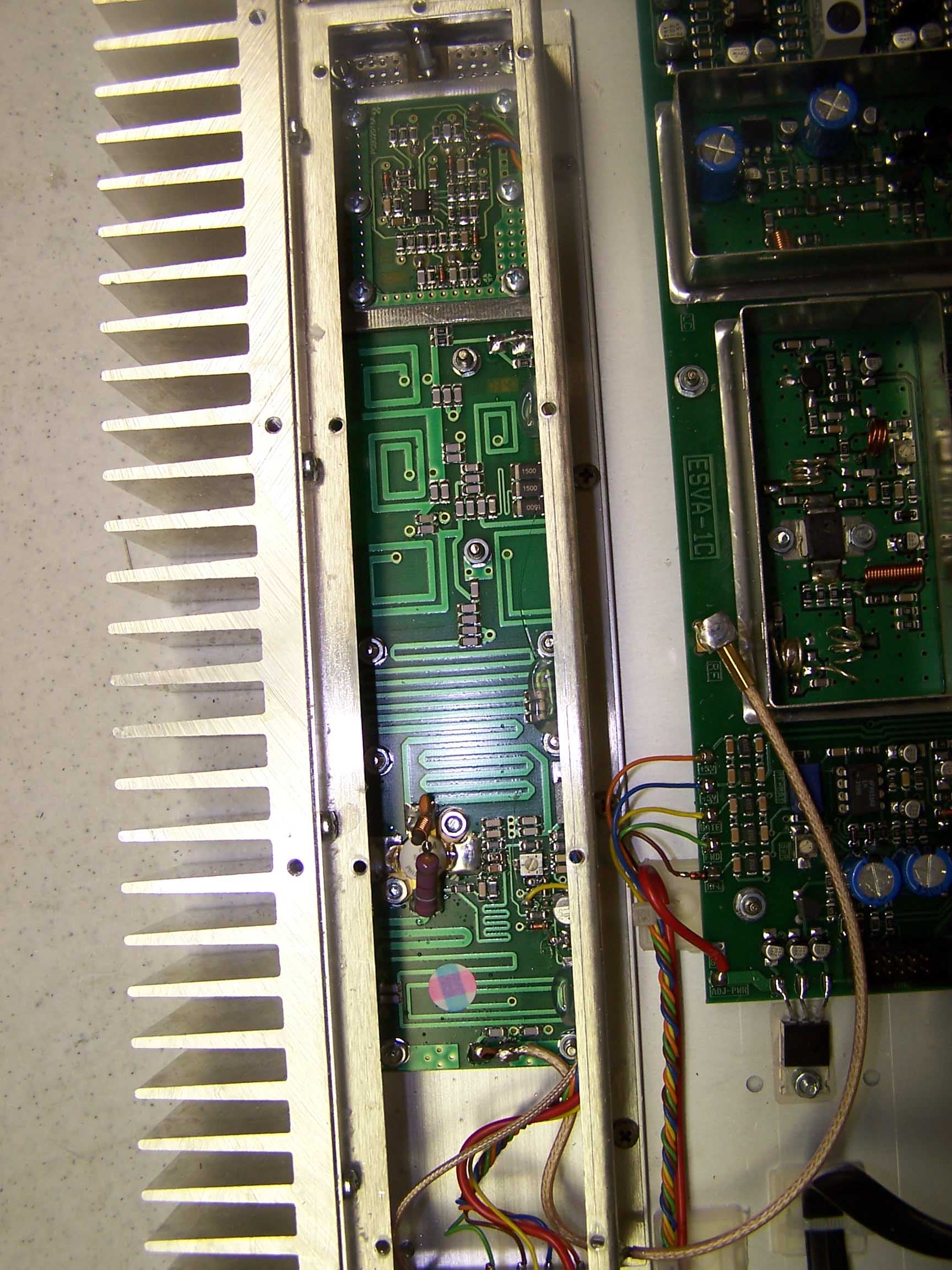
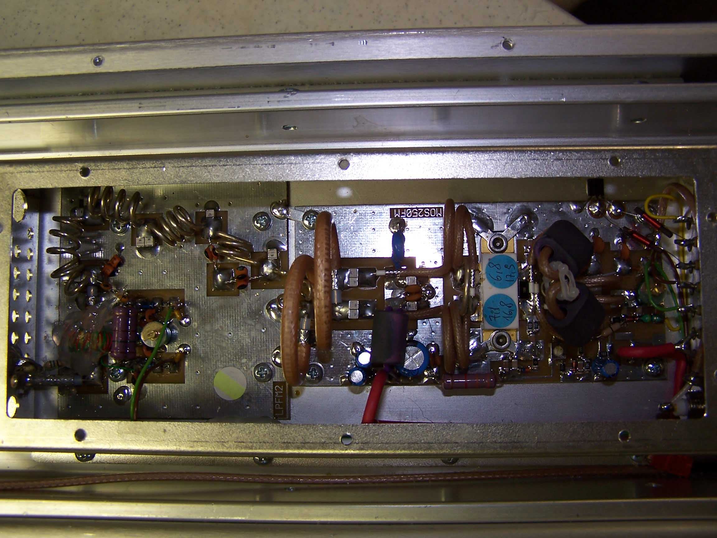
FM TRANSMITTER NBE250 Technical features of RF driver section and RF final power stage The driver stage is placed in the main board and it is composed by two active devices, the first one is a BFR96S working on AB class that has an output of 0,2W, then the true driving device is an LDMOS mod. PD55003 by ST Microelectronics, and below the technical working specifications: Vcc 15 V Idq 25 mA IDC at Full Power 850 mA Power Gain >13 dB Output Power > 4W Frequency range87.5 – 108 MHz Polarization B class The signal, after going out from the driver, goes to the final power stage made by a double Mos-Fet mod. SD2932 by ST and then to a low pass filter and a notch circuit tuned on 176MHz, after then the signal passes trough a directional coupler for sampling the forward and reflected RF power. Below the technical specifications of the power stage: Vcc 48 V Idq 50 mA IDC at Full Power 7.6 A typ. Power Gain >18 dB Output Power > 250W Frequency range 87.5 – 108 MHz Polarization B class Below the low pass filter specifications: In band insertion loss < 0.3dB Insertion Loss @ 175 MHz > 60dB In band return loss < - 30dB Here below we can see a photo of the NBE 250 RF module amplifier
Parts List/Tune Up Info
NEXUS BROADCASTNEXUS BROADCAST Rif.ValueRemarksDescriptionCode C139pFSMD Multilayer Ceramic Capacitor C239pFSMD Multilayer Ceramic Capacitor C30.1MFSMD Multilayer Ceramic Capacitor C439pFSMD Multilayer Ceramic Capacitor C539pFSMD Multilayer Ceramic Capacitor C60.1MFSMD Multilayer Ceramic Capacitor C71000MF16VAluminium Electrolytic Capacitor C82.2MF50VSMD Aluminium Electrolytic Capacitor C92.2MF50VSMD Aluminium Electrolytic Capacitor C101000MF16VAluminium Electrolytic Capacitor C110.1MFSMD Multilayer Ceramic Capacitor C1210MF35VSMD Aluminium Electrolytic Capacitor C130.1MFSMD Multilayer Ceramic Capacitor C140.1MFSMD Multilayer Ceramic Capacitor C1510MF35VSMD Aluminium Electrolytic Capacitor C16100pFSMD Multilayer Ceramic Capacitor C173.3pFSMD Multilayer Ceramic Capacitor C182.2MF50VSMD Aluminium Electrolytic Capacitor C19100pFSMD Multilayer Ceramic Capacitor C2047MF16VSMD Aluminium Electrolytic Capacitor C2122pFSMD Multilayer Ceramic Capacitor C2222MF16VSMD Aluminium Electrolytic Capacitor C2322MF16VSMD Aluminium Electrolytic Capacitor C240.1MFSMD Multilayer Ceramic Capacitor C250.1MFSMD Multilayer Ceramic Capacitor C26? C27? C28? C292.2MF50VSMD Aluminium Electrolytic Capacitor C300.1MFSMD Multilayer Ceramic Capacitor C31470MF16VAluminium Electrolytic Capacitor C321000MF16VAluminium Electrolytic Capacitor C33470MF 35VAluminium Electrolytic Capacitor C3422MF16VSMD Aluminium Electrolytic Capacitor C351nFSMD Multilayer Ceramic Capacitor C3622MF16VSMD Aluminium Electrolytic Capacitor C372.2MF50VSMD Aluminium Electrolytic Capacitor C3860pFTrimmer Polyethylene Film Capacitor C3910pFSMD Multilayer Ceramic Capacitor C4010pFSMD Multilayer Ceramic Capacitor C41470pFSMD Multilayer Ceramic Capacitor C421000MF35VAluminium Electrolytic Capacitor C43? C44470pFSMD Multilayer Ceramic Capacitor C46470pFSMD Multilayer Ceramic Capacitor C4710MF25VSMD Aluminium Electrolytic Capacitor C48470MF 35VAluminium Electrolytic Capacitor C49470MF 35VAluminium Electrolytic Capacitor Part List Schematic : ESVA1B NEXUS BROADCASTNEXUS BROADCAST Rif.ValueRemarksDescriptionCode C5010MF25VSMD Aluminium Electrolytic Capacitor C51? C524.7nFSMD Multilayer Ceramic Capacitor C53100MF16VAluminium Electrolytic Capacitor C546.8nFSMD Multilayer Ceramic Capacitor C55100MF16VAluminium Electrolytic Capacitor C5647pFSMD Multilayer Ceramic Capacitor C5747pFSMD Multilayer Ceramic Capacitor C5810MF25VSMD Aluminium Electrolytic Capacitor C590.1MFSMD Multilayer Ceramic Capacitor C600.1MFSMD Multilayer Ceramic Capacitor C610.1MFSMD Multilayer Ceramic Capacitor C6222pFSMD Multilayer Ceramic Capacitor C6322pFSMD Multilayer Ceramic Capacitor C64220pFSMD Multilayer Ceramic Capacitor C6510pFSMD Multilayer Ceramic Capacitor C661000MF35VAluminium Electrolytic Capacitor C6747MF 35VAluminium Electrolytic Capacitor C68470MF 35VAluminium Electrolytic Capacitor C69220MF 35VAluminium Electrolytic Capacitor C700.1MFSMD Multilayer Ceramic Capacitor C710.1MFSMD Multilayer Ceramic Capacitor C720.1MFSMD Multilayer Ceramic Capacitor C730.1MFSMD Multilayer Ceramic Capacitor C7422MF16VSMD Aluminium Electrolytic Capacitor C750.1MFSMD Multilayer Ceramic Capacitor C760.1MFSMD Multilayer Ceramic Capacitor C7722MF16VSMD Aluminium Electrolytic Capacitor C780.1MFSMD Multilayer Ceramic Capacitor C790.1MFSMD Multilayer Ceramic Capacitor C801000MF16VAluminium Electrolytic Capacitor C810.1MFSMD Multilayer Ceramic Capacitor C8247MF 35VAluminium Electrolytic Capacitor C8347MF 35VAluminium Electrolytic Capacitor C840.1MFSMD Multilayer Ceramic Capacitor C8522MF16VSMD Aluminium Electrolytic Capacitor C860.1MFSMD Multilayer Ceramic Capacitor C8710nFSMD Multilayer Ceramic Capacitor C8847MF 35VAluminium Electrolytic Capacitor C8947MF 35VAluminium Electrolytic Capacitor C900.1MFSMD Multilayer Ceramic Capacitor C9122MF16VSMD Aluminium Electrolytic Capacitor C920.1MFSMD Multilayer Ceramic Capacitor C9347MF 35VAluminium Electrolytic Capacitor C94220MF35VAluminium Electrolytic Capacitor C95220MF35VAluminium Electrolytic Capacitor C960.1MFSMD Multilayer Ceramic Capacitor C970.1MFSMD Multilayer Ceramic Capacitor C982.2MF50VSMD Aluminium Electrolytic Capacitor C992.2MF50VSMD Aluminium Electrolytic Capacitor C10010MF25VSMD Aluminium Electrolytic Capacitor NEXUS BROADCASTNEXUS BROADCAST Rif.ValueRemarksDescriptionCode C101470MF35VAluminium Electrolytic Capacitor C1020.1MFSMD Multilayer Ceramic Capacitor C1032.2MF50VSMD Aluminium Electrolytic Capacitor C1042.2MF50VSMD Aluminium Electrolytic Capacitor C1052.2MF50VSMD Aluminium Electrolytic Capacitor C106100pFSMD Multilayer Ceramic Capacitor C10710MF25VSMD Aluminium Electrolytic Capacitor C1082.2MF50VSMD Aluminium Electrolytic Capacitor C109100pFSMD Multilayer Ceramic Capacitor C1100.1MFSMD Multilayer Ceramic Capacitor C111?SMD Multilayer Ceramic Capacitor C112?SMD Multilayer Ceramic Capacitor C113?SMD Multilayer Ceramic Capacitor C11439pFSMD Multilayer Ceramic Capacitor C11539pFSMD Multilayer Ceramic Capacitor C11639pFSMD Multilayer Ceramic Capacitor C11739pFSMD Multilayer Ceramic Capacitor C11839pFSMD Multilayer Ceramic Capacitor C11939pFSMD Multilayer Ceramic Capacitor C12039pFSMD Multilayer Ceramic Capacitor C12139pFSMD Multilayer Ceramic Capacitor C1222.2MF20VSMD Tantalum Capacitor C1233.3pFSMD Multilayer Ceramic Capacitor C1240.47MF50VAluminium Electrolytic Capacitor C125100MF16VAluminium Electrolytic Capacitor L110μHFerrite Drum Cored Inductor L210μHFerrite Drum Cored Inductor L32.2μHSMD Inductor L422μHSMD Inductor L58T/0.6DEnamelled Copper Wire L622μHSMD Inductor L7VK200Ferrite Drum Cored Inductor L82T/.6DEnamelled Copper Wire L94.7mHFerrite Drum Cored Inductor L10CHOKESuppression Choke L1122μHFerrite Drum Cored Inductor L12? L13CHOKESuppression Choke L14CHOKESuppression Choke L15CHOKESuppression Choke L16CHOKESuppression Choke Rext11010WAluminium Clad Wirewound Resistor Rext20.510WAluminium Clad Wirewound Resistor Rext310K1/4WCermet Skeleton Trimmer Resistor R1221/4WSMD Thick Film Resistor R23301/4WSMD Thick Film Resistor R3221/4WSMD Thi…
Text truncated - open the document above for the full version.
Parts List/Tune Up Info
NEXUS BROADCASTNEXUS BROADCAST Rif.ValueRemarksDescriptionCode C1100nFSMD Multilayer Ceramic Capacitor C3100nFSMD Multilayer Ceramic Capacitor C210MF35VSMD Aluminium Electrolytic Capacitor C41nFSMD Multilayer Ceramic Capacitor R156KSMD Thick Film Resistor R3180SMD Thick Film Resistor R2180SMD Thick Film Resistor R410KSMD Thick Film Resistor R50SMD Thick Film Resistor D11N4148SMD Low Power Signal Diode D21N4148SMD Low Power Signal Diode D31N4148SMD Low Power Signal Diode TCXO112.800MHzTCXO U178L05Fixed Voltage Regulator Part List Schematic : TCXO-01
Parts List/Tune Up Info
NEXUS BROADCASTNEXUS BROADCAST Rif.ValueRemarksDescriptionCode C110MF25VSMD Tantalum Capacitor C233pFSMD Multilayer Ceramic Capacitor C30.1MFSMD Multilayer Ceramic Capacitor C40.1MFSMD Multilayer Ceramic Capacitor C633pFSMD Multilayer Ceramic Capacitor C70.1MFSMD Multilayer Ceramic Capacitor C8100MF6VSMD Tantalum Capacitor C91MF16VSMD Tantalum Capacitor C100.1MFSMD Multilayer Ceramic Capacitor C111MF16VSMD Tantalum Capacitor C121MF16VSMD Tantalum Capacitor C131MF16VSMD Tantalum Capacitor C141MF16VSMD Tantalum Capacitor R110K1/4WSIL Thick Film Resistor Network R210K1/4WSMD Thick Film Resistor R310K1/4WSMD Thick Film Resistor R410K1/4WSMD Thick Film Resistor R510K1/4WSMD Thick Film Resistor R610K1/4WSMD Thick Film Resistor R710K1/4WSMD Thick Film Resistor R810K1/4WSMD Thick Film Resistor R910K1/4WSMD Thick Film Resistor R1010K1/4WSMD Thick Film Resistor R111K21/4WSMD Thick Film Resistor R126K81/4WSIL Thick Film Resistor Network Q1BC557Bipolar Transistor U1ADC08234A/D Converter U2AT89S8252Microporcessor U3MAX232Special Function Integrated Circuit U5MAX812LSpecial Function Integrated Circuit LCD1V20350LCD Display Y111.0592 MHzQuartz Crystal J1DJ2PCB Pin Strip Header J2DJ3PCB Pin Strip Header J3CON16Male PCB Mounting Header Part List Schematic : MICRO00A
Parts List/Tune Up Info
NEXUS BROADCASTNEXUS BROADCAST Rif.ValueRemarksDescriptionCode R110KMulti Turn Cermet Trimmer Resistor Panel Mount D1GREENLight Emitting Diode D2GREENLight Emitting Diode D3YELLOWLight Emitting Diode Part List Schematic : ESVAFP1
Parts List/Tune Up Info
NEXUS BROADCASTNEXUS BROADCAST Rif.ValueRemarksDescriptionCode C11nFCeramic Disc Capacitor C210MF63VAluminium Electrolytic Capacitor C3100nFMultilayer Ceramic Capacitor C44.7nFCeramic Disc Capacitor C533pFCeramic Disc Capacitor C833pFCeramic Disc Capacitor C6220pFCeramic Disc Capacitor C710pFCeramic Disc Capacitor L115T/3DEnamelled Copper Wire L23T/6DTinned Copper Wire L33T/6DTinned Copper Wire L43T/6DTinned Copper Wire L5CHOKESuppression Choke R13901/4WCarbon Film Resistor R24.71/4WCarbon Film Resistor R45.61/4WCarbon Film Resistor R35.61/4WCarbon Film Resistor R52701/4WCarbon Film Resistor TR1RF Transformer Q1MRF237RF Bipolar Transistor J1BNCBNC Bulkhead Connector - 50 Ohm J2BNCBNC Bulkhead Connector - 50 Ohm Part List Schematic : RFD4W-C
Parts List/Tune Up Info
NEXUS BROADCASTNEXUS BROADCAST Rif.ValueRemarksDescriptionCode C1NCSMD Multilayer Ceramic Capacitor C2NCSMD Multilayer Ceramic Capacitor C3470pFSMD Multilayer Ceramic Capacitor C410pFSMD Multilayer Ceramic Capacitor C510pFSMD Multilayer Ceramic Capacitor C618pFSMD Multilayer Ceramic Capacitor C710MF50VSMD Aluminium Electrolytic Capacitor C847nF SMD Multilayer Ceramic Capacitor C92.2nFSMD Multilayer Ceramic Capacitor C1010nFSMD Multilayer Ceramic Capacitor C11220pFSMD Multilayer Ceramic Capacitor C128.2pFSMD Multilayer Ceramic Capacitor C138.2pFSMD Multilayer Ceramic Capacitor C1422pFSMD Multilayer Ceramic Capacitor C1522pFSMD Multilayer Ceramic Capacitor C1622pFSMD Multilayer Ceramic Capacitor C17470pFSMD Multilayer Ceramic Capacitor C18470pFSMD Multilayer Ceramic Capacitor C1968pFSMD Multilayer Ceramic Capacitor C2068pFSMD Multilayer Ceramic Capacitor C2110nFSMD Multilayer Ceramic Capacitor C2210nFSMD Multilayer Ceramic Capacitor C2310nFSMD Multilayer Ceramic Capacitor C2418pFSMD Multilayer Ceramic Capacitor C2518pFSMD Multilayer Ceramic Capacitor C2615pFSMD Multilayer Ceramic Capacitor C2739pFSMD Multilayer Ceramic Capacitor C28220pFSMD Multilayer Ceramic Capacitor C2918pFSMD Multilayer Ceramic Capacitor C3068pFSMD Multilayer Ceramic Capacitor C3118pFSMD Multilayer Ceramic Capacitor C3268pFSMD Multilayer Ceramic Capacitor C334.7pFSMD Multilayer Ceramic Capacitor C3482pFSMD Multilayer Ceramic Capacitor C3515pFSMD Multilayer Ceramic Capacitor C3647pFSMD Multilayer Ceramic Capacitor C3768pFSMD Multilayer Ceramic Capacitor C3810nFSMD Multilayer Ceramic Capacitor C3939pFSMD Multilayer Ceramic Capacitor C4039pFSMD Multilayer Ceramic Capacitor C4122pFSMD Multilayer Ceramic Capacitor C4256pFSMD Multilayer Ceramic Capacitor C4356pFSMD Multilayer Ceramic Capacitor L1CHOKESuppression Choke MST1Microstrip Inductor MST2Microstrip Inductor MST3Microstrip Inductor MST4Microstrip Inductor Part List Schematic : RFAMP-20W-1B NEXUS BROADCASTNEXUS BROADCAST Rif.ValueRemarksDescriptionCode MST5Microstrip Inductor MST6Microstrip Inductor MST7Microstrip Inductor MST8Microstrip Inductor MST9Microstrip Inductor MST10Microstrip Inductor MST11Microstrip Inductor MST12Microstrip Inductor MST13Microstrip Inductor R110K1/4 WSMD Thick Film Resistor R210K1/4 WSMD Thick Film Resistor R31501 WSMD Thick Film Resistor R4561/4 WSMD Thick Film Resistor R53K31/4 WSMD Thick Film Resistor R61501 WSMD Thick Film Resistor R71501 WSMD Thick Film Resistor R83K31/4 WSMD Thick Film Resistor R9221/4 WSMD Thick Film Resistor R10221/4 WSMD Thick Film Resistor R1122K1/4 WSMD Thick Film Resistor R125K61/4 WSMD Thick Film Resistor R136.81/4 WSMD Thick Film Resistor R1422K1/4 WSMD Thick Film Resistor R152201/4 WSMD Thick Film Resistor R16220K1/4 WSMD Thick Film Resistor RT147K1/4 WSMD Cermet Skeleton Trimmer Resistor D1LL4148SMD Low Power Signal Diode DZ13V9SMD Diode Zener DZ23V9SMD Diode Zener Q1BLF245RF MOSFET NEXUS BROADCASTNEXUS BROADCAST
Parts List/Tune Up Info
NEXUS BROADCASTNEXUS BROADCAST Rif.ValueRemarksDescriptionCode C110nFSMD Multilayer Ceramic Capacitor C268pFSMD Multilayer Ceramic Capacitor C3470pFSMD Multilayer Ceramic Capacitor C410nFSMD Multilayer Ceramic Capacitor C5220nFSMD Multilayer Ceramic Capacitor C6470pFSMD Multilayer Ceramic Capacitor C768pFSMD Multilayer Ceramic Capacitor C8220nFSMD Multilayer Ceramic Capacitor R1330K1/4 WSMD Thick Film Resistor R2220K1/4 WSMD Thick Film Resistor R322K1/4 WSMD Thick Film Resistor R42K21/4 WSMD Thick Film Resistor R56K81/4 WSMD Thick Film Resistor R6681/4 WSMD Thick Film Resistor R71801/4 WSMD Thick Film Resistor R822K1/4 WSMD Thick Film Resistor R9270K1/4 WSMD Thick Film Resistor R10390K1/4 WSMD Thick Film Resistor R111M1/4 WSMD Thick Film Resistor R12330K1/4 WSMD Thick Film Resistor R1322K1/4 WSMD Thick Film Resistor R14220K1/4 WSMD Thick Film Resistor R152K21/4 WSMD Thick Film Resistor R161201/4 WSMD Thick Film Resistor R176K81/4 WSMD Thick Film Resistor R18681/4 WSMD Thick Film Resistor R19270K1/4 WSMD Thick Film Resistor R2022K1/4 WSMD Thick Film Resistor R21561/4 WSMD Thick Film Resistor R22390K1/4 WSMD Thick Film Resistor R231M1/4 WSMD Thick Film Resistor R241001/4 WSMD Thick Film Resistor R251001/4 WSMD Thick Film Resistor IC1TLC272SMD Operational Amplifier Part List Schematic : COUPLER 1B
Parts List/Tune Up Info
TUNE UP PROCEDURE NBE-20, NBE-100 AND NBE-250 The NBE Fm exciter series utilizes state of the art technology, therefore there is nothing for the end user to “tune” and setup is a breeze. Please consult the users manual for setting the frequency via the front panel controls. Power is adjusted by a small potentiometer located on the front of the unit. Power may be varied from zero to twenty watts. Power level as well as reflected power is indicated on the LCD display on the front of the unit. Modulation adjust is adjusted in the same manner by a potentiometer on the back of the unit. Modulation for the main channel, SCA, etc are adjusted with a small jewelers tip screwdriver. Modulation levels for the composite input can be monitored on the front Panel LCD display. The unit will operate on 90 – 220 VAX 60 or 50 HZ. This is automatically adjusted in the units power supply. No user intervention is required.
RF Exposure Info
WARNING: RF Hazard Information THE ANTENNA(S) USED FOR THIS TRANSMITTER MUST BE FIXED-MOUNTED ON OUTDOOR PERMANENT STRUCTURES. RF EXPOSURE COMPLIANCE IS ADDRESSED AT THE TIME OF LICENSING, AS REQUIRED BY THE RESPONSIBLE FCC BUREAU(S) INCLUDING ANTENNA CO-LOCATION REQUIREMENTS OF PARA. 1.1307(B)(3). WARNING! THE VOLTAGES AND CURRENTS IN THIS EQUIPMENT ARE DANGEROUS. PERSONEL MUST, AT ALL TIMES, OBSERVE SAFETY WARNINGS, INSTRUCTIONS, AND ANY REGULATIONS. This owner’s manual is intended as a general guide for trained and qualified personnel who are aware of the dangers that are inherent in the handling and operation of potentially hazardous electrical and electronic circuits. It is not the intent of this manual to provide a complete set of safety instructions or precautions that should already be understood by trained or experienced personnel in using this or other types of electronic equipment. The installation, operation, and maintenance of this equipment involves risks to personnel and also to the equipment. Nexus Broadcast Products shall not be responsible for injury or damage that is the result of improper procedures or use by persons improperly trained or lacking the knowledge to perform associated tasks. All local codes for building, safety, fire, or related standards must be observed. Consult local authorities for the standards for the area or region where the equipment will be installed and put in use. WARNING! AT ALL TIMES DISCONECT AC/MAINS POWER BEFORE OPENING COVERS, DOORS, ENCLOSURES, PANELS, OR PROTECTIVE SHIELDS THAT EXPOSE LIVE CIRCUITS. USE ANY GROUNDING STICKS OR OTHER SHORTING PROBES TO DRAIN ENERGY FROM CIRCUITS BEFORE SERVICING. NEVER PERFORM MAINTENANCE, MAKE ADJUSTMENTS, OR SERVICE THE EQUIPMENT WHEN ALONE OR FATIGUED. WARNING! IF ELECTROLYTIC OR OIL FILLED CAPACITORS ARE UTILIZED IN THE EQUIPMENT AND THE COMPONENT APPEARS LEAKY, OR IS BULGING, OR IF THE CASE OR COVERING OF THE COMPONENT APPEARS DAMAGED OR DISTRESSED ALLOW SUFFICIENT TIME FOR THE UNIT TO COOL OR FULLY DISCHARGE BEFORE SERVICING. SERVICING HOT OR LEAKY CAPACITORS CAN CAUSE A RUPTURE OF THE CASE AND POSSIBLE INJURY. Should accident or injury occur personnel engaged in the installation, operation, or service of the equipment should seek proper medical attention. It is advisable that such personnel have familiarity with first-aid practices.
Schematics
VCO AUDIO INPUT RF DRVER RF AMPLIFIER PLL LIMITER TCXO 12.8 MHz LPF DIRECTIONAL COUPLER POWER SWITCHING SUPPLY SIGNAL INTERFACE MICROCONTROLLER DISPLAY N E X U S MPX MONO SCA ADJ RS232 VDCVAC RF OUTPUT MHz 98.000 Mod. NBE20 1.0 FUNCTIONAL SCHEMATIC B 11Tuesday, December 23, 2003 Title SizeDocument NumberRev Date:Sheetof NEXUS BROADCASTNEXUS BROADCAST
Schematics
MHZ 98.000 N L GND 100÷240VAC MP X MO NO SCA1SCA2SCA3 IN TERLOCK RF OUTPUT N E X U S Mod. NBE20 1.0 GENERAL SCHEMATIC B 11Thursday, December 27, 2001 Title SizeDocument NumberRev Date:Sheetof NEXUS BROADCASTNEXUS BROADCAST ESVA BOARD V. DRIVER MPX GND MPX MONO+ GND MONO MO NO- SC A1 GND SC A1 Interlo ck GND Interlo ck SC A2 GND SC A2 SC A3 GND SCA3 +24V GND V- GATE -12V GND _ FORWA RD POWER REFL ECTED POWER +24V _ J2-PROGRAMMER & MET ER J4-LED & ADJ POWER DJ 3-RS232 RF OUTP UT TE MPERATURE POWER SUPPLY L N GND HEAR T +24VGND MICROCONTROLLER PROGRAMMER & METER RF AMPLIFIER RF OUTPUT RF INPUT V. G ATE V. DRIVER +24VFORWARD POWERREFL ECTED POWER TEMPERATURE GND -12V CONTROL PANEL LED & ADJ POWER EMC F ILTER L O UT N OUT L IN N IN GND HEAR T FUSE B FUSE A GND TX RX 2A 6A 7A 3A7A 1A3A2A 4A 4A 1A 6A 5A 5A P1 RS232 5 9 4 8 3 7 2 6 1 JR1 XRL C+- G L1 CHO KE L5 CHO KE L4 CHO KE L7 CHO KE L6 CHO KE L2 CHO KE L3 CHO KE F1 1A J1 N J2 BNC J3 BNC J4 BNC J5 BNC J6 BNC FAN1 12
Schematics
Mod. EMC-02 1.0 EMC FILTER A 11Tuesday, December 16, 2003 Title SizeDocument NumberRev Date:Sheet of NEXUS BNEXUS BROADCASTROADCAST L2 0.8mH L1 0.8mH C2 1uF / 350V C3 2.2nF / 350V C1 2.2nF / 350V L IN GND EARTH N IN L OUT GND EARTH N OUT
Schematics
RF OUT AUX Mod. …
Text truncated - open the document above for the full version.
Contact Information
Applicant
Leo Ashcraft
Technical Contact
Nexus Broadcast ProductsLeo Ashcraft
903-577-9191
403 South Madison Avenue · Mount Pleasant, Texas · United States
Non-Technical Contact
Nexus Broadcast ProductsLeo Ashcraft
903-577-9191
Test Firm
Nemko USA, Inc.Tom Tidwell
Technical Specifications
| # | Rule Parts | Frequency Range | Power Output | Emission | Tolerance |
|---|---|---|---|---|---|
| 3 | 73 | 88.1 MHz - 107.9 MHz | 250 W | 200KF3E | 387 Hz |
Other Applications from Nexus Broadcast Products
RR4NBSTL10
Apr 15, 2004Studio to Transmitter Link
Equipment Class
TNB - Licensed Non-Broadcast Station Transmitter