RRY01WT-01RF-Transceiver (for touch board)
Beauty Up Co., Ltd.
Click to zoom
Application Details
- Equipment Class
- DXT - Part 15 Low Power Transceiver, Rx Verified
- Date of Grant
- Jun 03, 2004
- Application Purpose
- Original Equipment
- Date of Application
- Jun 03, 2004
- Equipment Note
- RF-Transceiver (for touch board)
- Frequency Range
- 2416.00000000 - 2478.00000000
- Company
- Beauty Up Co., Ltd.
- Country
- Taiwan
Documents & Files
Document Text
Text extracted from the exhibit documents filed with the FCC. Open a document above to read the original.
Users Manual
I nteractive T ouch B oard Let’s make the world wonderful. 75” Wireless(ITB-011)Interactive Touch Board I nteractive T ouch B oard Installation and User Manual --------------------------------------------------------------1--------------------------------------------------------------2 -------------------------4 --------------------------------------------4--------------------------------------------5 ----6 ----------------------------------------------------------7 -------------------------------------------------13 --------------------------------------------------18 --------------------------------------------------------21 ------------------------------------------------------23 ---------------------------------------------------------------24 --------------------------------------------------------------24 --------------------------------------30 ------------------------------------39 -----------------------------------------39 ------------39 ---------------------------------------40 ------------------------------------------44 -----------------------------------------------45 ------------------------48 -----------------------------------------52 ----------------------------------------------52 -----------------------------------------53 --------------------------------------54 ---------------------55 --------------56 -----------------------------------------------------------------57 Table Of Contents 1. Safety Notes2. Product Frame3. Specification and System Environment 3.1 Board Specification 3.2 Tablet specification3.3 Wireless Transceiver and Receiver specification 4. Wall Installation5. Moveable Installation6. Software Installation7. Total Test Flow8. Brief Introduction9. Operations 9.1 Driver 9.2 The Annotate program9.3 Handwriting recognition 9.3.1 How to start it9.3.2 Handwriting recognition explained9.3.3 System Setting9.3.4 Invisible IME9.3.5 Learning9.3.7 New Fast Hand Explained9.3.8 Sign Language9.3.9 Uninstall 9. 4 Onscreen Keyboard 10. Frequently Asked Questions11. Appendix A: Accessories of (Wall Type)12. Appendix B: Accessories of (Moveable Type)13. Services www.beauty-up.com.tw Installation and User Manual Services 13 Installation and User Manual 57 Services SUPPORPRODUCT Register BUTC Sales DepartmentTEL : +886-2-2223 9889 (Mon. ~ Fri. AM 8:30~PM05:30)FAX : +886-2-2223 8725 Email : Web : www.beauty-up.com.tw Product Maintain : 2 Years Maintain ID : The Series Number Service : The product maintain by BUTC company.If there is any questi on, please call BUTC Sales Department for help. There is a “ Register Card “ within the IT-Board package-box. In order to provide you for best service, please sign and send it back to “Beauty Up Co., Ltd.” www.beauty-up.com.tw www.beauty-up.com.tw 02 Product Frame : 2 Installation and User Manual WiredWireless For wiredFor wireless Product Frame 01 Safety Notes : 1 Installation and User Manual www.beauty-up.com.tw Safety Notes 1. Read this safety notes before any attempt to install/operate the board.. 2. Keep this instruction menu in a safe place for further reference. 3. Do not rip off, damage, over band, twist or over-stretch the power cable of serial cable, or use them to bind other objects, especially keep heavy objects away from the power cable in order to prevent danger or accidents. 4. Keep installation environment dry. 5 . Keep cautious while moving the IT-Board. 6. Do not use powerful detergents or alcohol or thinners to clean the surface of the board. 7. Keep this board away form he at sources and magnified object. 8. Do not attempt to fix the board by yourself. In case of malfunction,call us for service instead. 9. Do not allow children play around the board or using sharp objects to damage the board . 10. Check wheel breaks are open before moving the board. And, do not move this board on the asphalt road if it is not necessary. 11. Make sure the replacement parts is recognized by the manufactures. 12. If store the board, please keep its front side face up. RS-232 & USB Switching Adapter AC100-200V(50-60Hz)0.5A/DC-5V,2A-10W Maximize resolution 1016LPI RF/2.4G Hz (ISM Band ) FSK transceiver Serial 10M AC120V(60Hz)/DC 5V 300MA RS-232 or USB Port 120~240 Axis Per second +/-45 ° 10mm 512step (With Pen Brush function) +/-0.01” 500 LPI 03 Product Frame www.beauty-up.com.tw Installation and User Manual 1. Need to use with projector 。 2. Using the Front-projection on the Board, then you can control as using 75 inches screen. 3. The product can be used in teaching / remote learning / Enterprise Intra-Meeting / Business Meeting / Net Meeting / training / discussion / Control center system / VOIP / entertainment / digitize house control system. 4. You should set up step by step as the manual.5. Operation : (1)RS-232 Cable - To connect PC or Notebook with USB or RS-232 interface, and you can line, write, paint and use the Microsoft office to save, print and Email. (2)Wireless - Using RF receiver and transfer to control IT-Board. Index : Wireless 1710W X 1355H X 40D (mm ± 2%) Body SizeHumidity -10 ° ~ 50 ° Temperature RS232lengthPower SupplyInterfaceData SpeedPen SlopeSense rangeGray ScalePrecisionResolutionData Transmission Anti-Glare Polymer Maternal IT Board and Projector Screen Usage 1524W X 1143H (mm ± 0.5mm) Sensing Area Body 34Kg ( ± 1Kg)+Pen Slot 1.5kg( ± 0.5Kg) Hanger 2.5Kg( ± 0.5Kg) Frame 25Kg ( ± 1Kg) + hooks 2Kg( ± 0.5Kg) Weight 1685W X 1640H X 600D (mm ± 2%) Frame Size 1170W X 64H X 23D (mm ± 2%) Hanger Size Wired Specification and System Environment 3 Installation and User Manua l 3.1 Board Specification 04 Specification and System Environment www.beauty-up.com.tw Board specification 0~95% RF/2.4G Hz Wireless Receiver (RS-232 and USB) 3.2 Tablet specification +/-0.01” Precision 0~95%RF(2.4GHz) Wireless Receiver(RS-232 and USB) 235W X 225H X 21D (mm ± 2%) Body Size RF/2.4G Hz (ISM Band ) FSK transceiver Humidity -10 ° ~ 50 ° Temperature NO.4(AAA)battary x 4 Power PC 131 Axis Per second Pen Slope +/-60 ° Pen Slope 10mm Sens…
Text truncated - open the document above for the full version.
Users Manual
28 www.beauty-up.com.tw When in use, pen pressure value are from 1 to 512. The driver are able to reflect this. All you have to do is preset the value. In “ Show ” setting to see how actual pressure are set. The diagram indicate the change after setting. e.g. Pressure value = 200 , Show = 300 , means the pen top can accept change between 1~200, but it actually indicate that there are 1~300. One set value means 1.5 actual value Default : Set both pressure and show value back to default valueAfter setting, put a file name into the column of current file. Then save it, it will be save in *.ini format, locate in C:\IT-BOARD. Plus a path file Max Wining. If you want to erase any personal setting, you must delete them both. Note: Only English characters and digits are acceptable. Exit : Close the program Operations Driver 27 www.beauty-up.com.tw Area : Controllable area of the IT-Board To understand how big the controllable area of the Board.Calibration : align cursor with pen Default Mapping : Maximum controllable area Screen Mapping : modify area with regular 4:3 screen. In some cases, the controllable area are not 4:3, click the “ Screen Mapping ” to adjust it. Pressure : Pen pressure setting Start pressure : Initialize setting Pressure rate : Pressure change rates You are able to personalize this setting according to your custom. When “ Start Pressure ” is set, you test it with test button. When the pressure reach the value you set, a black rectangular shape will surround the button. Preset value is 1. Note: Preset value cannot exceed 150 Operations Driver Installation and User Manual Installation and User Manual 29 www.beauty-up.com.tw Calibration: Before use stick or pen, you must align cursor and pen top by calibration. Right Click the icon to open function and click on calibration (fig 1, fig 2), Point the stick top on middle of the cross and press first button of the stick (fig 3). Then you are able to use stick/pen as a mouse. Fig 1Fig 2Fig 3 Operations Driver 30 www.beauty-up.com.tw 9.2 The Annotate program Here is a note writing application within New Quick called Annotate. Click the icon to start the Annotate.The following icon will appear after you start the Annotate. Annotate Explained: It is a note making program, for all the applications which is able to enter the graphs. Annotate is able to create the notes you desire. Beside of other drawing functions, Annotate is able to simulate the paintbrush and make the word rainbow-like It also able to send the notes you created into your e-mail applications such as Outlook express, Outlook, Netscape Messenger and Eudora. Annotate is compatible with MS Office series (Word, Excel, PowerPoint) for creating notes and annotations: The notes you create is located exactly on the top of the word you wish to explain. It is easy for writer to decide whether make note appear, or just delete them. For example, after someone modify a document, he is able to circle where it should modify with Annotate and hand it to another person, after another person fix all the parts, he is able to delete the notes. Which make job easier. Operation The Annotate program Installation and User Manual Installation and User Manual click and do the writing/drawing 7 31 www.beaut y -u p .com.tw Buttons explained 9 1 2 3 4 5 6 7 8 10 11 12 13 Button functions click and choose color from the list 2 click and select the size of pen 3 close Annotacolor of the penThicknessHide all the notes.OptionHelpPencil 12 3 45 6 7 89 10 11 1213 Draw a loneDraw a squireDraw a circleSing mature modeloadDelete click and you will be able to draw straight line, round shape, or square. You may fill the round/square by press stick/pen button for two second. 8 9 10 Operation The Annotate program 32 www.beaut y -u p .com.tw 11 Click the will change into “recover” and “back , you may use it when you make mistakes during editing(you may repeat many times as long as you are not saving it. 5 6 7 8 9 10 Click special pen will be available: paintbrush,you may also use multi-layer/color feature. 11 11 Click this button to erase everything you have draw/write. The Annotate program Operation click toolbar will change like this: Installation and User Manual Installation and User Manual 33 www.beauty-up.com.tw press an introductory dialog willappear 。 6 press to display setting box 7 Auto : after check this box, whatever you have done by the Annota will be automatically save. Zoom : The handwriting graph will be adjust to the size you set while saving file/graph. Stable Size : The size of your writing/drawing will not change while saving file Check this box so the toolbar will be minimize after a period of time. 12 Click this button to confirm whatever you have wrote/draw. OperationThe Annotate program 34 www.beauty-up.com.tw In case of delete all annotation, please press this button to display this dialog box. A button “Delete all annotation within this document” will appear. Click it to delete all annotation. Fig 1 Fig 2 Fig 3 5 Fig 4 Fig 5 Fig 6 Fig 7 Annota toolbox (above)may be used after you have save annotation.operate : click edit then press , to hide annotations on the text , and button will change color to fig 5. Press the annotation will re-appear. ( see fig. 6 and fig. 7 to see actual operation. ) 4 4 4 4 Operation The Annotate program Installation and User Manual Installation and User Manual 35 www.beauty-up.com.tw Actual Operation Click this button so you will be able to draw lines. 1 Click this button for drawing straight line. 2 Click this button to draw rectangle box. 3 How to use Annota 36 www.beauty-up.com.tw Click this box to draw circle 4 Click this button to draw/write with different style. 5 Click this box to draw/write with different color. 6 How to use Annota Installation and User Manual Installation and User Manual 37 www.beauty-up.com.tw Special Function [Shift key] + = Drawing straight line [Shift key] + = Drawing square. [Shift key] + = drawing round shape [Ctrl key] + = drawi…
Text truncated - open the document above for the full version.
External Photos
Page 1 FCC ID: RRY01WT-01 CONSTRUCTION PHOTOS OF EUT
ID Label/Location Info
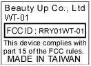
(Fig. 1) FCC ID: RRY01WT-01 FCC LABEL LOCATION The label will be permanently affixed at a conspicuous location on the device. Label
Internal Photos
Page 2 FCC ID: RRY01WT-01 Page 3 FCC ID: RRY01WT-01 Page 4 FCC ID: RRY01WT-01 Page 5 FCC ID: RRY01WT-01 Page 6 FCC ID: RRY01WT-01 Page 7 FCC ID: RRY01WT-01 Page 8 FCC ID: RRY01WT-01 Page 9 FCC ID: RRY01WT-01
Operational Description
FCC ID: RRY01WT-01 Report No.: RF921107A061Issued: March 30, 2004 Operational Description The EUT is a RF module, designed for 2.4GHz ISM band wireless applications using AMIC 7101 FSK transceiver. This module features a fully programmable frequency synthesizer by SPI. The data rate is 57.6Kbps or 64Kbps. The EUT is consumed power from adapter. The antenna type used in this product is a mono coil antenna attached to the EUT. The other instruction, please have a look at the Module specification.
Operational Description
MD7101_PA Preliminary 2.4GHz FSK High Power Transceiver PA module specification MD7101_PA (DEMO) PRELIMINARY (July, 2003, Version 0.1) AMIC Technology, Corp. MD7101_PA General Description The MD7101_PA module is designed for 2.4GHz ISM band wireless applications using AMIC A7101 FSK transceiver. This module features a fully programmable frequency synthesizer by SPI. The data rate is 57.6Kbps or 64Kbps. Electrical specification Item Specification Remark Supply voltage 3.0 – 3.3 V Current consumption 6mA(typical) @sleep mode 8mA(typical) @stand-by mode 154mA(typical) @Tx mode, high power 36mA(typical) @Rx mode MD7101_PA Tx/Rx switch[1:0]=00 for sleep and standby mode Frequency 2416 – 2478 MHz Transmit output power +4 ± 2 dBm @ high power, VIN = 3.3V Rx sensitivity -86 dBm (typical) BER 1E-3 Modulation FSK Transmission distance 15 meters (typical) Interface 15 pin 1.25mm header Dimension 47(L) x 25(W) x 1(H) mm 3 Operating temperature 0 – 50 PRELIMINARY (December, 2002, Version 0.0) 1 AMIC Technology, Corp. MD7101_PA Interface Pin Number Pin Name Description Note 1 Switch[1:0]=10, Tx mode, PA enable 2 Tx /Rx Switch Switch[1:0]=01, Rx mode, LNA enable 3 VIN Supply voltage. 4 EN_REG Voltage regulator enable pin. Signal is active high. 5 SPI_LATCH Latch for SPI interface 6 SPI_CLOCK Clock for SPI interface. 7 SPI_DATA Data for SPI interface. 8 LVOUT Battery-Low voltage indicator output. This pin is active low when LVIN is below BP_REG voltage level. 9 LD PLL locked detect indicator output, active high (open drain). 10 TXDATAIN Transmitter data input 11 MUTE Receiver mute control output pin. 12 EN_AFC AFC circuit control pin. 13 XTALOUT Buffered crystal oscillator output. 14 RXDATA Receiver data output. 15 GND Ground. PRELIMINARY (December, 2002, Version 0.0) 2 AMIC Technology, Corp. MD7101_PA Serial to Parallel Interface (SPI) The SPI bus consists of three signals: SPI_DATA, SPI_CLOCK, and SPI_LATCH. This interface is used for external base-band controller to communicate with internal registers. The contents of the registers are shown in the following register description sections. After setting SPI_LATCH signal to “Low” state, data on SPI_DATA is shifted into the internal shift register on the rising edge of SPI_CLOCK with MSB going in first. SPI_LATCH should be asserted at the end to latch the data packet into the register according to the address bits, bit 0 through bit 3, for each of the registers. All registers can only be written into except the Status Register which can only be read. When the content of the Status Register need to be fetched by external controller, external baseband controller need to make sure that the address bits are pointing to address location 0x0 for proper read operation. After the address bits are shifted into the SPI interface and latched by asserting SPI_LATCH, the SPI interface will be in Read Mode and the content of the Status Register will be shifted out on SPI_DATA pin. When all 12 status bits have been shifted out, the SPI bus will be put back to Write Mode automatically. A. Register Description Note: Convention used: 1: Logic level “ONE”. 0: Logic level “ZERO”. X: Don’t care. Synthesizer Configuration Register I (Write only / Address 0xf) Bit 15 Bit 14 Bit 13 Bit12 Bit11 Bit10 Bit9 Bit8 Bit7 Bit6 Bit5 Bit4 Bit3 Bit2 Bit 1 Bit 0 MB6 MB5 MB4 MB3 MB2 MB1 MB0 MA4 MA3 MA2 MA1 MA0 1 1 1 1 Synthesizer Configuration Register II (Write only / Address 0x7) Bit 15 Bit 14 Bit 13 Bit12 Bit11 Bit10 Bit9 Bit8 Bit7 Bit6 Bit5 Bit4 Bit3 Bit2 Bit 1 Bit 0 X MB9 MB8 MB7 R7 R6 R5 R4 R3 R2 R1 R0 0 1 1 1 Synthesizer Configuration Register I and Synthesizer Configuration Register II control synthesizer frequency settings where MA[4:0]: A counter[4:0] . Valid range is from 0 to 31. MB[9:0]: B counter[9:0] . Valid range is from 0 to 1023. R[7:0]: R counter[7:0] . Valid range is from 2 to 255, for this module must be set to 0x78 at Rx mode and 0x18 at Tx mode. The content of A, B and R registers are in unsigned binary format (i.e., 11111 2 = 31 10 ). The equation for setting the synthesizer frequency is: f vco = f crystal * (32*B + A) / R, (B A). For example : For Rx mode If f vco = 2450MHz , f crysta = 12MHz , f reference = 100KHz. Then R = f crysta / f reference = 120 = 01111000 2 , B = 765 = 1011111101 2 , A = 20 = 10100 2 . For Tx mode If f vco = 2450MHz , f crysta = 12MHz , f reference = 500KHz. Then R = f crysta / f reference = 24 = 00011000 2 , B = 153 = 0010011001 2 , A = 4 = 00100 2 . PRELIMINARY (December, 2002, Version 0.0) 3 AMIC Technology, Corp. MD7101_PA Crystal Control Register (Write only / Address 0xb) Bit 15 Bit 14 Bit 13 Bit12 Bit11 Bit10 Bit9 Bit8 Bit7 Bit6 Bit5 Bit4 Bit3 Bit2 Bit 1 Bit 0 0 DP TXH2 TXH1 TXH0 TXL2 TXL1 TXL0 FX3 FX2 FX1 FX0 1 0 1 1 DP: Data Polarity. This control bit sets data output polarity. 0: Data is inverted. 1: Normal. TXH[2:0]: Must be set to 0x0 for proper operation. TXL[2:0]: Must be set to 0x0 for proper operation. FX[3:0]: Must be set to 0x0 for proper operation. VCO Control Register (Write only / Address 0x3) Bit 15 Bit 14 Bit 13 Bit12 Bit11 Bit10 Bit9 Bit8 Bit7 Bit6 Bit5 Bit4 Bit3 Bit2 Bit 1 Bit 0 VTH2 VTH1 VTH0 T1 T0 HP0 CP2 CP1 CP0 VC2 VC1 VC0 0 0 1 1 VTH[2:0]: Set VCO tuning voltage range, for this module must be set to 0x6 for proper operation. 0x0 = 0.3 to VDD-0.3V , 0x1 = 0.4 to VDD-0.4V , 0x2 = 0.5 to VDD-0.5V , 0x3 = 0.6 to VDD-0.6V , 0x4 = 0.7 to VDD-0.7V , 0x5 = 0.8 to VDD-0.8V , 0x6 = 0.9 to VDD-0.9V , 0x7 = 1.0 to VDD-1.0V , T[1:0]: Reserved. Must be set to 0x0 for proper operation. HP0: RF output power level control. 0: Low power output (-16 dBm), for this module please set to low power mode when it operate on Tx mode.. 1: High power output (-6 dBm). CP[2]: Reserved. Must be set to 0x0 for proper operation. CP[1:0]: Charge pump output current control, for this module must be set to 0x1(300uA) for proper operation. 0x0 = 100uA , 0x1 = 300uA , 0x2 = 500uA , 0x3 = 700uA , VC[2:0]: Reserved. Must be set to 0x4 for proper ope…
Text truncated - open the document above for the full version.
Test Report
FCC ID: RRY01WT-01 Report No.: RF921107A06 1Issued: March 30, 2004 FCC TEST REPORT REPORT NO.: RF921107A06 MODEL NO.: WT-01 RECEIVED: Nov. 7, 2003 TESTED: March 19 ~ 30, 2004 APPLICANT: Beauty Up Co., Ltd. ADDRESS: 6F, No. 3, Jenge Rd., Chung-Ho City, Taipei Hsien,Taiwan, R.O.C. ISSUED BY: Advance Data Technology Corporation LAB LOCATION: 47 14th Lin, Chiapau Tsun, Linko, Taipei, Taiwan, R.O.C. This test report consists of 38 pages in total. It may be duplicated completely for legal use with the approval of the applicant. It should not be reproduced except in full, without the written approval of our laboratory. The client should not use it to claim product endorsement by CNLA or any government agencies. The test results in the report only apply to the tested sample. The test results in this report are traceable to the national or international standards. 0528 ILAC MRA FCC ID: RRY01WT-01 Report No.: RF921107A06 2Issued: March 30, 2004 Table of Contents 1CERTIFICATION............................................................................................. 3 2SUMMARY OF TEST RESULTS .................................................................... 4 3GENERAL INFORMATION ............................................................................. 5 3.1GENERAL DESCRIPTION OF EUT ................................................................5 3.2DESCRIPTION OF TEST MODE ....................................................................6 3.3DESCRIPTION OF APPLIED STANDARD ......................................................6 3.4DESCRIPTION OF SUPPORT UNITS ............................................................7 4EMISSION TEST ............................................................................................ 8 4.1CONDUCTED EMISSION MEASUREMENT...................................................8 4.1.1 LIMITS OF CONDUCTED EMISSION MEASUREMENT ................................8 4.1.2 TEST INSTRUMENTS.....................................................................................9 4.1.3 TEST PROCEDURE......................................................................................10 4.1.4 DEVIATION FROM TEST STANDARD..........................................................10 4.1.5 TEST SETUP................................................................................................. 11 4.1.6 EUT OPERATING CONDITIONS .................................................................. 11 4.1.7 TEST RESULTS ............................................................................................12 4.2RADIATED EMISSION MEASUREMENT......................................................18 4.2.1 LIMITS OF RADIATED EMISSION MEASUREMENT ...................................18 4.2.2 TEST INSTRUMENTS...................................................................................19 4.2.3 TEST PROCEDURE......................................................................................20 4.2.4 DEVIATION FROM TEST STANDARD..........................................................20 4.2.5 TEST SETUP.................................................................................................21 4.2.6 EUT OPERATING CONDITIONS ..................................................................21 4.2.7 TEST RESULTS ............................................................................................22 4.3BAND EDGES MEASUREMENT ..................................................................30 4.3.1 LIMITS OF BAND EDGES MEASUREMENT ................................................30 4.3.2 TEST INSTRUMENTS...................................................................................30 4.3.3 TEST PROCEDURE......................................................................................30 4.3.4 DEVIATION FROM TEST STANDARD..........................................................30 4.3.5 EUT OPERATING CONDITION.....................................................................30 4.3.6 TEST RESULTS ............................................................................................31 5PHOTOGRAPHS OF THE TEST CONFIGURATION ................................... 34 6APPENDIX I – MEASUREMENT OF CONDUCTED SPURIOUS EMISSION FOR THE 10 TH HARMONIC .......................................................................... 36 7APPENDIX II - INFORMATION ON THE TESTING LABORATORIES ......... 38 FCC ID: RRY01WT-01 Report No.: RF921107A06 3Issued: March 30, 2004 1 CERTIFICATION PRODUCT:RF-Transceiver (for touch board) BRAND NAME:BUTC MODEL NO.:WT-01 TEST ITEM:ENGINEERING SAMPLE APPLICANT:Beauty Up Co., Ltd. MANUFACTURER:Maxwin System Technology Corp. STANDARDS:FCC Part 15, Subpart C (Section 15.249) ANSI C63.4-1992 We, Advance Data Technology Corporation, hereby certify that one sample of the designation has been tested in our facility from March 19 ~ 30, 2004. The test record, data evaluation and Equipment Under Test (EUT) configurations represented herein are true and accurate accounts of the measurements of the sample's EMC characteristics under the conditions herein specified. PREPARED BY:, DATE:March 30, 2004 APPROVED BY:, DATE:March 30, 2004 ( Mike Su, Manager ) ( Yemmy Soong ) FCC ID: RRY01WT-01 Report No.: RF921107A06 4Issued: March 30, 2004 2 SUMMARY OF TEST RESULTS The EUT has been tested according to the following specifications: APPLIED STANDARD: 47 CFR Part 15, Subpart C Standard Section Test Type and LimitResultREMARK 15.207Conducted EmissionPASS Meet the requirement of limit Minimum passing margin is –17.30dB at 29.031MHz 15.249Transmitter Radiated EmissionsPASS Meet the requirement of limit Minimum passing margin is –3.00dB at 82.48MHz 15.249Band Edge MeasurementPASS Meet the requirement of limit Note: 1. The information of measurement uncertainty is available upon the customer’s request. FCC ID: RRY01WT-01 Report No.: RF921107A06 5Issued: March 30, 2004 3 GENERAL INFORMATION 3.1 GENERAL DESCRIPTION OF EUT PRODUCTRF-Transceiver (for touch board…
Text truncated - open the document above for the full version.
Test Setup Photos
FCC ID: RRY01WT-01 Report No.: RF921107A06 34Issued: March 30, 2004 5 PHOTOGRAPHS OF THE TEST CONFIGURATION CONDUCTED EMISSION TEST FCC ID: RRY01WT-01 Report No.: RF921107A06 35Issued: March 30, 2004 RADIATED EMISSION TEST
Contact Information
Applicant
Stephen Lin(R&D)
Technical Contact
Advance Data Technology CorporationEllis Wu
[email protected]+886 3318 3232
13-1, Lane 19, WenShan 3rd St. · Taoyuan · Taiwan
Non-Technical Contact
Advance Data Technology CorporationYemmy Soong
[email protected]+886 22605 2180
Test Firm
Bureau Veritas CPS (H.K.) Ltd. Taoyuan BranchRichard Chen
Technical Specifications
| # | Rule Parts | Frequency Range | Power Output |
|---|---|---|---|
| 1 | 15C | 2.42 GHz - 2.48 GHz | - |