RTU0401Break Guard
Mission Microsystems, Inc.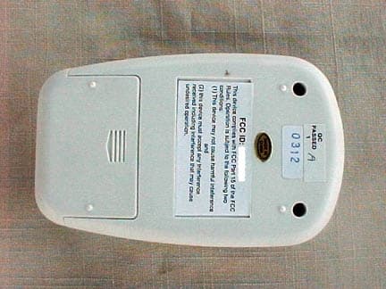
Click to zoom
Application Details
- Equipment Class
- DSC - Part 15 Security/Remote Control Transmitter
- Date of Grant
- Feb 23, 2004
- Application Purpose
- Original Equipment
- Date of Application
- Feb 23, 2004
- Equipment Note
- Break Guard
- Frequency Range
- 303.83500000 - 303.83500000
- Company
- Mission Microsystems, Inc.
- Country
- United States
Documents & Files
Document Text
Text extracted from the exhibit documents filed with the FCC. Open a document above to read the original.
Users Manual
BreakGuard™ Setup Instructions Step 1 – Remove rear battery compartment cover by sliding away from unit. Step 2 – Adjust sensitivity switch (inside battery compartment) to the middle position (M). Step 3 - Insert 9-volt top post battery (not included). Make sure the plus and minus signs on the battery align with the plus and minus signs in the battery compartment. Step 4 - Replace battery compartment cover. Step 5 – Depress button on face of BreakGuard™ unit and confirm indicator light illuminates steadily. Depress button to extinguish light. Step 5 – Cut a 2 inch by 2 inch swath of single-sided self-adhesive Velcro™ (included) and apply to back of BreakGuard™ unit. Step 6 – Pre-cut sections of two-sided Velcro™ (included) to wrap around transfer hose (protected hose) providing for a minimum 2 inch overlap (for 2” delivery hose approximately 12 inches). Note: these sections can be reused. Operating Instructions Step 1 – Wrap a pre-cut section of two-sided Velcro™ (see Step 6 above) around the transfer hose (protected hose) at approximately the midpoint of the hose. Make sure Velcro™ overlaps by a minimum of 2 inches. Step 2 – Depress button on face of BreakGuard™ unit until red indicator light is illuminated steadily. Step 3 – Press BreakGuard™ unit to the Velcro™ wrap on the hose until the Velcro™ on the back of the BreakGuard™ interlocks with the Velcro™ on the protected hose. Confirm indicator light is still on. INSTRUCTION TO THE USER This equipment has been tested and found to comply with the limits for a class B digital device, pursuant to part 15 of the FCC Rules. These limits are designed to provide reasonable protection against harmful interference in a residential installation. This equipment generates, uses and can radiate radio frequency energy and if not installed and used in accordance with the instructions, may cause harmful interference to radio communications. However, there is no guarantee that interference will not occur in a particular installation. If this equipment does cause harmful interference to radio or television reception, which can be determined by turning the equipment off and on, the user is encouraged to try to correct the interference by one or more of the following measures: • Re-Orient or relocate the receiving antenna. • Increase the separation between the equipment and receiver • Connect the equipment into an outlet on a circuit different from that to which the receiver is connected. • Consult the dealer or an experienced radio/TV technician for help This equipment has been certified to comply with the limits for a class B computing device, pursuant to FCC rules. Operation with non-approved equipment is likely to result in interference to radio and TV reception. The user is cautioned that changes and modifications made to the equipment without the approval of manufacturer could void the user’s authority to operate this equipment.
Attestation Statements
Mission Microsystems, Inc. http://www.missionmicro.com/ 5942 Edinger Ave. Suite #113-PMB719, Huntington Beach, CA 92649-1773 (714)-841-1986 FAX: (714)-841-1036 EMAIL: mailto:[email protected] February 6, 2004 1 Page ATTN: To whom it may concern CC: From: Bill McDonough SUBJECT: McTier Break Guard Transmitter modifications Based upon results obtained during FCC Part 15 compliance testing at Compatible Laboratories on January 30, we will make the following changes before commencing production. R2 was 100 ohms, now 47 ohm +-5%. C7 was 1000pF now 0.1uF Sincerely, William B. McDonough President 1
Cover Letter(s)
1 Mission Microsystems, Inc. http://www.missionmicro.com/ 5942 Edinger Ave. Suite #113-PMB719, Huntington Beach, CA 92649-1773 (714)-841-1986 FAX: (714)-841-1036 EMAIL: mailto:[email protected] January 30, 2004 Federal Communications Commission Equipment Approval Services P.O. Box 358315 Pittsburgh, PA 15251-5315 Subject: Request for withholding from public disclosure the schematic diagram, block diagram, and operational description pursuant to an application for certification. Gentleman: We (Mission Microsystems Inc), would like to request that all schematics, block diagrams, and operational descriptions submitted with our application for certification be withheld from public disclosure per Section 0.459 of the FCC rules. This request is mad under the provisions of Section 0.457(d) of the Commissions rules, and Section 522 (b)(4) of the Freedom of Information Act. These sections authorize the withholding from public inspection, those materials which would be privileged as a matter of law if retained by the person submitting them, and materials which would not customarily be released to the public by that person. If you have any questions or need any additional information, please give me a call at (714)-841-1986. Sincerely, William B. McDonough President
ID Label/Location Info
FCC ID: RTU0401 This device complies with FCC Part 15 of the FCC Rules. Operation is subject to the following two conditions: (1) This device may not cause harmful inteference and (2) this device must accept any interference received including interference that may cause undesired operation.
Test Report
Report Number: B40130A1 FCC Part 15 Subpart B and FCC Section 15.231 Test Report Break Guard Model: 0401 Brea Division 114 Olinda Drive Brea, CA 92823 (714) 579-0500 Agoura Division 2337 Troutdale Drive Agoura, CA 91301 (818) 597-0600 Silverado Division 19121 El Toro Road Silverado, CA 92676 (949) 589-0700 Lake Forest Division 20621 Pascal Way Lake Forest, CA 92630 (949) 587-0400 Page 1 of 15 FCC PART 15, SUBPART B and C TEST REPORT for BREAK GUARD MODEL: 0401 Prepared for MISSION MICRSYSTEMS, INCORPORATED 5942 EDINGER AVENUE, SUITE 113 – PMB 719 HUNTINGTON BEACH, CA 92649-1773 Prepared by:_____________________ MICHAEL CHRISTENSEN Approved by:____________________ KYLE FUJIMOTO COMPATIBLE ELECTRONICS INC. 114 OLINDA DRIVE BREA, CALIFORNIA 92823 (714) 579-0500 DATE: FEBRUARY 2, 2004 REPORT APPENDICES TOTAL BODY A B C D E PAGES 15 2 2 2 8 16 45 This report shall not be reproduced except in full, without the written approval of Compatible Electronics. Report Number: B40130A1 FCC Part 15 Subpart B and FCC Section 15.231 Test Report Break Guard Model: 0401 Brea Division 114 Olinda Drive Brea, CA 92823 (714) 579-0500 Agoura Division 2337 Troutdale Drive Agoura, CA 91301 (818) 597-0600 Silverado Division 19121 El Toro Road Silverado, CA 92676 (949) 589-0700 Lake Forest Division 20621 Pascal Way Lake Forest, CA 92630 (949) 587-0400 Page 2 of 15 TABLE OF CONTENTS Section / Title PAGE GENERAL REPORT SUMMARY 4 SUMMARY OF TEST RESULTS 4 1. PURPOSE 5 2. ADMINISTRATIVE DATA 6 2.1 Location of Testing 6 2.2 Traceability Statement 6 2.3 Cognizant Personnel 6 2.4 Date Test Sample was Received 6 2.5 Disposition of the Test Sample 6 2.6 Abbreviations and Acronyms 6 3. APPLICABLE DOCUMENTS 7 4. DESCRIPTION OF TEST CONFIGURATION 8 4.1 Description Of Test Configuration - EMI 8 4.1.1 Cable Construction and Termination 9 5. LISTS OF EUT, ACCESSORIES AND TEST EQUIPMENT 10 5.1 EUT and Accessory List 10 5.2 EMI Test Equipment 11 6. TEST SITE DESCRIPTION 12 6.1 Test Facility Description 12 6.2 EUT Mounting, Bonding and Grounding 12 7. TEST PROCEDURES 13 7.1 Radiated Emissions (Spurious and Harmonics) Test 13 7.2 Bandwidth of the Fundamental 14 8. CONCLUSIONS 15 Report Number: B40130A1 FCC Part 15 Subpart B and FCC Section 15.231 Test Report Break Guard Model: 0401 Brea Division 114 Olinda Drive Brea, CA 92823 (714) 579-0500 Agoura Division 2337 Troutdale Drive Agoura, CA 91301 (818) 597-0600 Silverado Division 19121 El Toro Road Silverado, CA 92676 (949) 589-0700 Lake Forest Division 20621 Pascal Way Lake Forest, CA 92630 (949) 587-0400 Page 3 of 15 LIST OF APPENDICES APPENDIX TITLE A Laboratory Recognitions B Modifications to the EUT C Additional Models Covered Under This Report D Diagrams, Charts, and Photos • Test Setup Diagrams • Radiated Emissions Photos • Antenna and Effective Gain Factors E Data Sheets LIST OF FIGURES FIGURE TITLE 1 Plot Map And Layout of Radiated Site Report Number: B40130A1 FCC Part 15 Subpart B and FCC Section 15.231 Test Report Break Guard Model: 0401 Brea Division 114 Olinda Drive Brea, CA 92823 (714) 579-0500 Agoura Division 2337 Troutdale Drive Agoura, CA 91301 (818) 597-0600 Silverado Division 19121 El Toro Road Silverado, CA 92676 (949) 589-0700 Lake Forest Division 20621 Pascal Way Lake Forest, CA 92630 (949) 587-0400 Page 4 of 15 GENERAL REPORT SUMMARY This electromagnetic emission test report is generated by Compatible Electronics Inc., which is an independent testing and consulting firm. The test report is based on testing performed by Compatible Electronics personnel according to the measurement procedures described in the test specifications given below and in the "Test Procedures" section of this report. The measurement data and conclusions appearing herein relate only to the sample tested and this report may not be reproduced without the written permission of Compatible Electronics, unless done so in full. This report must not be used to claim product endorsement by NVLAP, NIST or any other agency of the U.S. Government. Device Tested: Break Guard Model: 0401 S/N: N/A Product Description: See Expository Statement Modifications: The EUT was modified in order to meet the specifications. Please see the list located in Appendix B. Manufacturer: Mission Microsystems, Incorporated 5942 Edinger Avenue, Suite 113 – PMB 719 Huntington Beach, CA 92649-1773 Test Date: January 30, 2004 Test Specifications : EMI requirements CFR Title 47, Part 15 Subpart B; and Subpart C, Sections 15.205, 15.209 and 15.231 Test Procedure: ANSI C63.4: 2001 Test Deviations: The test procedure was not deviated from during the testing. SUMMARY OF TEST RESULTS TEST DESCRIPTION RESULTS 1 Conducted RF Emissions, 150 kHz - 30 MHz This test was not performed because the EUT operates on DC power only and cannot be plugged into the AC public mains. 2 Radiated RF Emissions, 303.8 MHz - 3040 MHz Complies with the Class B limits of CFR Title 47, Part 15, Subpart B; and Subpart C, sections 15.205, 15.209, and 15.231. Report Number: B40130A1 FCC Part 15 Subpart B and FCC Section 15.231 Test Report Break Guard Model: 0401 Brea Division 114 Olinda Drive Brea, CA 92823 (714) 579-0500 Agoura Division 2337 Troutdale Drive Agoura, CA 91301 (818) 597-0600 Silverado Division 19121 El Toro Road Silverado, CA 92676 (949) 589-0700 Lake Forest Division 20621 Pascal Way Lake Forest, CA 92630 (949) 587-0400 Page 5 of 15 1. PURPOSE This document is a qualification test report based on the Electromagnetic Interference (EMI) tests performed on the Break Guard Model: 0401. The EMI measurements were performed according to the measurement procedure described in ANSI C63.4: 2001. The tests were performed in order to determine whether the electromagnetic emissions from the equipment under test, referred to as EUT hereafter, are within the Class B specification limits defined by CFR Title 47, Part 15, Subpart B; and Subpart C, sections 15.205, 15.209, and 15.231. Report Number: B40130A1 FCC Part 15 Subpart B and FCC Section 15.231 Test Report B…
Text truncated - open the document above for the full version.
Contact Information
Applicant
William B. McDonough(President)
Technical Contact
Compatible ElectronicsMike P Christensen
[email protected]714-579-0500
114 Olinda Drive · Brea, California · United States
Test Firm
Compatible ElectronicsScott McCutchan
714-579-0500Fax: 714-579-1850
Technical Specifications
| # | Rule Parts | Frequency Range | Power Output |
|---|---|---|---|
| 1 | 15.231 | 303.835 MHz - 303.835 MHz | - |