FCCID.CO- FCC ID Database
HomeCompaniesEquipment ClassesSearch

© 2026 FCC ID Database. All rights reserved.

AboutContactData sourced from FCC public records
  1. Home/
  2. HKC Technology Ltd./
  3. RTZ238

RTZ2385.8GHz DSSS Cordless Phone System w/ CID & DAM

HKC Technology Ltd.
5.8GHz DSSS Cordless Phone System w/ CID & DAM - FCC ID RTZ238 - HKC Technology Ltd.
Click to zoom

Application Details

Equipment Class
JBP - Part 15 Class B Computing Device Peripheral
Date of Grant
Apr 07, 2004
Application Purpose
Original Equipment
Date of Application
Apr 07, 2004
Equipment Note
5.8GHz DSSS Cordless Phone System w/ CID & DAM
Company
HKC Technology Ltd.
Country
China

Documents & Files

Select a file to view
Users Manual

↗
↗

Cover Letter(s)

↗

External Photos

↗

ID Label/Location Info

↗

Internal Photos

↗

Test Report

↗
↗

Test Setup Photos

↗
↗

Document Text

Text extracted from the exhibit documents filed with the FCC. Open a document above to read the original.

Users Manual

Circle Communication Products, Inc 5.8GHz Multi-line and Multi-handset Cordless Telephone System Configuration Guide Version 2.20 Circle Communication Products, Inc 5.8G Cordless Telephone System configuration guide Page 2 COPYRIGHT COPYRIGHT 2003, Circle Communication Products, Inc. ALL RIGHTS RESERVED. This manual is the copyright of Circle Communication Products, Inc. You may not reproduce, transmit, transcribe, store in a retrieval system, or translate into any language, in any form or by any means, electronic, mechanical, magnetic, optical, chemical, manual, or otherwise, any part of this publication without the express written permission of Circle Communication Products, Inc. Disclaimer Circle Communication Products, Inc. makes no representations or warranties regarding the content of this manual. We reserve the right to revise the manual or make changes in the specifications of the product described within it at any time without notice and without obligation to notify any person of such revision or change. Circle Communication Products, Inc 5.8G Cordless Telephone System configuration guide Page 3 Table of Contents COPYRIGHT....................................................................................................................................................2 D ISCLAIMER .......................................................................................................................................................2 INTRODUCTION..................................................................................................................................................6 P ACKAGE C ONTENT ............................................................................................................................................6 INSTALLATION...................................................................................................................................................7 O VERVIEW OF M AIN C ONTROL B ASE ...................................................................................................................7 E QUIPMENT L OCATION ........................................................................................................................................7 I NSTALLATION OF T HE M AIN C ONTROL B ASE ........................................................................................................8 C HARGING THE B ATTERY ....................................................................................................................................9 C ONNECTION OF T ELEPHONE L INE ......................................................................................................................9 C ONNECTION OF E XTERNAL MOH (M USIC ON H OLD )........................................................................................9 C ONNECTION OF P AGING S YSTEM ( OPTION ).........................................................................................................9 C ONNECTION OF S INGLE L INE P HONE FOR P OWER F AILURE T RANSFER ( OPTION )................................................10 S OFTWARE I NSTALLATION .................................................................................................................................10 CALL FEATURES DESCRIPTIONS..................................................................................................................11 A UTO A TTENDANCE (AA)..................................................................................................................................11 A UTOMATIC C ALL B ACK ON B USY ......................................................................................................................11 A UTOMATIC C ALL D ISTRIBUTION ........................................................................................................................11 A UTOMATIC R ECALL .........................................................................................................................................12 C ALL F ORWARD , A LL C ALLS ..............................................................................................................................12 C ALL F ORWARD , B USY .....................................................................................................................................12 C ALL F ORWARD , B USY OR N O A NSWER ............................................................................................................12 C ALL F ORWARD , N O A NSWER ...........................................................................................................................12 C ALL F ORWARD , TO E XTERNAL L INE .................................................................................................................13 C ALL F ORWARD , TO V OICE M AIL .......................................................................................................................13 C ALL H OLD , N ORMAL ........................................................................................................................................13 C ALL H OLD , E XCLUSIVE ....................................................................................................................................13 C ALL L OG ........................................................................................................................................................14 C ALL P AGING ...................................................................................................................................................14 C ALL P ICKUP , L INE ...........................................................................................................................................14 C ALL P ICKUP , E XTENSION .................................................................................................................................14 C ALL T RANSFER , L INE C ALL .......................…

Text truncated - open the document above for the full version.

Users Manual

Circle Communication Products, Inc 5.8G Cordless Telephone System configuration guide Page 69 Important Consumer Information When using this unit, basic safety precautions should always be followed to reduce the risk of fire, electric shock, or personal injury. Warning: Changes or modifications to this unit not expressly approved by the party responsible for compliance could void the user’s authority to operate the equipment. NOTE: 1) This equipment has been tested and found to comply with the limits for a Class B digital device, pursuant to Part 15 of the FCC Rules. These limits are designed to provide reasonable protection against harmful interference in a residential installation. This equipment generates, uses and can radiate radio frequency energy and, if not installed and used in accordance with the instructions, may cause harmful interference to radio communications. However, there is no guarantee that interference will not occur in a particular installation. If this equipment does cause harmful interference to radio or television reception, which can be determined by turning the equipment off and on, the user is encouraged to try to correct the interference by one or more of the following measures: ÌReorient or relocate the receiving antenna. ÌIncrease the separation between the equipment and receiver. ÌConnect the equipment into an outlet on a circuit different from that to which the receiver is needed. ÌConsult the dealer or an experienced radio/TV technician for help. 2) This equipment complies with Part 68 of the FCC rules and the requirements adopted by the ACTA. On the bottom of this equipment is a label that contains, among other information, a product identifier in the format US:AAAEQ##TXXXX. If requested, this number must be provided to the telephone company. 3) An applicable certification jacks Universal Service Order Codes (USOC) for the equipment is provided (i.e., RJ11C) in the packaging with each piece of approved terminal equipment. 5.8G Cordless Telephone System - Handheld Extension (WHE) user guide Page 35 12. Important Consumer Information When using this unit, basic safety precautions should always be followed to reduce the risk of fire, electric shock, or personal injury. Warning: Changes or modifications to this unit not expressly approved by the party responsible for compliance could void the user’s authority to operate the equipment. NOTE: 1) This equipment has been tested and found to comply with the limits for a Class B digital device, pursuant to Part 15 of the FCC Rules. These limits are designed to provide reasonable protection against harmful interference in a residential installation. This equipment generates, uses and can radiate radio frequency energy and, if not installed and used in accordance with the instructions, may cause harmful interference to radio communications. However, there is no guarantee that interference will not occur in a particular installation. If this equipment does cause harmful interference to radio or television reception, which can be determined by turning the equipment off and on, the user is encouraged to try to correct the interference by one or more of the following measures: ÌReorient or relocate the receiving antenna. ÌIncrease the separation between the equipment and receiver. ÌConnect the equipment into an outlet on a circuit different from that to which the receiver is needed. ÌConsult the dealer or an experienced radio/TV technician for help. 2) This equipment complies with Part 68 of the FCC rules and the requirements adopted by the ACTA. On the bottom of this equipment is a label that contains, among other information, a product identifier in the format US:AAAEQ##TXXXX. If requested, this number must be provided to the telephone company. 3) An applicable certification jacks Universal Service Order Codes (USOC) for the equipment is provided (i.e., RJ11C) in the packaging with each piece of approved terminal equipment. 4) A plug and jack used to connect this equipment to the premises wiring and telephone network must comply with the applicable FCC Part 68 rules and requirements adopted by the ACTA. A compliant telephone cord and modular plug is provided with this product. It is designed to be connected to a compatible modular jack that is also compliant. See installation instructions for details. 5) The REN is used to determine the number of devices that may be connected to a telephone line. Excessive RENs on a telephone line may result in the devices not ringing in response to an incoming call. In most but not all areas, the sum of RENs should not exceed five (5.0). To be certain of the number of devices that may be connected to a line, as determined by the total RENs, contact the local telephone company. [For products approved after July 23, 2001, the REN for this product is part of the product identifier that has the format US:AAAEQ##TXXXX. The digits represented by ## are the REN without a 5.8G Cordless Telephone System - Desktop Extension (WDE) user guide Page 36 12. Important Consumer Information When using this unit, basic safety precautions should always be followed to reduce the risk of fire, electric shock, or personal injury. Warning: Changes or modifications to this unit not expressly approved by the party responsible for compliance could void the user’s authority to operate the equipment. NOTE: 1) This equipment has been tested and found to comply with the limits for a Class B digital device, pursuant to Part 15 of the FCC Rules. These limits are designed to provide reasonable protection against harmful interference in a residential installation. This equipment generates, uses and can radiate radio frequency energy and, if not installed and used in accordance with the instructions, may cause harmful interference to radio communications. However, there is no guarantee that interference will not occur in a particular installation. If this equipment does cause harmful interference to radio or television…

Text truncated - open the document above for the full version.

External Photos

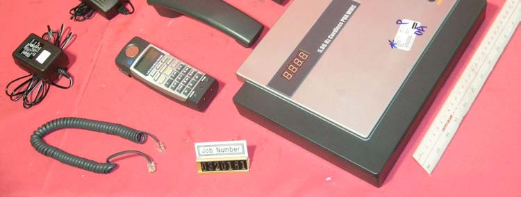
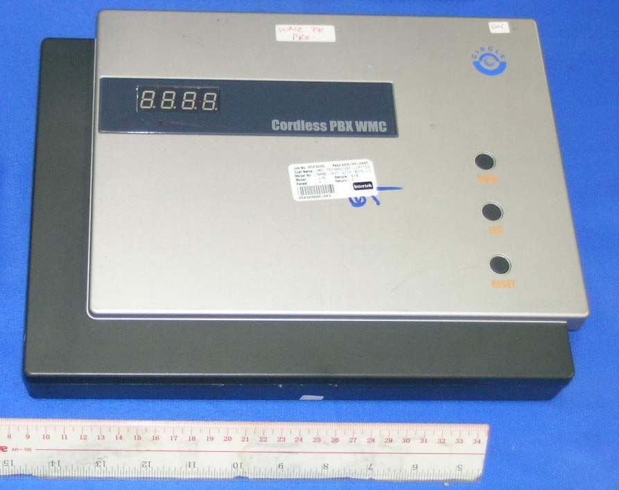
External photos FCC ID: RTZ238 External photos FCC ID: RTZ238

Internal Photos

Internal photos FCC ID: RTZ238 Base assembly Base Main PCB comp side Internal photos FCC ID: RTZ238 Base Main PCB solder side (View 1) Base Main PCB solder side (View 2) Internal photos FCC ID: RTZ238 Base display front side Base display rear side Internal photos FCC ID: RTZ238 Base Oscillator PCB comp side

Test Report

• The test results reported in this report shall refer only to the sample actually tested and shall not refer or be deemed to refer to bulk from which such a sample may be said to have been obtained. • This report shall not be reproduced except in full without prior authorization form Giant Electronics Limited Limited FCC ID: RTZ238 Intertek Testing Services Hong Kong Ltd. 2/F., Garment Centre, 576 Castle Peak Road, Kowloon, Hong Kong. Tel: (852) 2173 8888 Fax: (852) 2741 1693 Website: www.hk.intertek-etlsemko.com HKC Technology Ltd. Application For Certification 5.8GHz 10 Channel Digital Direct Sequence Spectrum Cordless Telephone System with Caller ID and Digital Answering Machine (FCC ID: RTZ238) 03201611 TL/Ann Choy March 1, 2004 INTERTEK TESTING SERVICES FCC ID: RTZ238 i LIST OF EXHIBITS INTRODUCTION EXHIBIT 1: Summary of Tests EXHIBIT 2: General Description EXHIBIT 3: System Test Configuration EXHIBIT 4: Measurement Results EXHIBIT 5: Equipment Photographs EXHIBIT 6: Product Labelling EXHIBIT 7: Technical Specifications EXHIBIT 8: Instruction Manual EXHIBIT 9: Security Code Information INTERTEK TESTING SERVICES FCC ID: RTZ238 ii MEASUREMENT/TECHNICAL REPORT HKC Technology Ltd.- MODEL: WMC, WDE, WHE FCC ID: RTZ238 This report concerns (check one) Original Grant X Class II Change Equipment Type: DSS-Part 15 Spread Spectrum Transmitter and Class B Personal Computer Peripheral Deferred grant requested per 47 CFR 0.457(d)(1)(ii)? Yes No X If yes, defer until : dae Company Name agrees to notify the Commission by: date of the intended date of announcement of the product so that the grant can be issued on that date. Transition Rules Request per 15.37? Yes No X If no, assumed Part 15, Subpart C for intentional radiator - the new 47 CFR [12- 08-03 Edition] provision. Report prepared by: Tommy Leung Intertek Testing Services 2/F., Garment Centre, 576 Castle Peak Road, Kowloon, Hong Kong. Phone: 852-2173-8538 Fax: 852-2741-1693 INTERTEK TESTING SERVICES FCC ID: RTZ238 iii Table of Contents 1.0 Summary of test results ............................................................................................................... 2 2.0 General Description ............................................................................................................... 4 2.1 Product Description .............................................................................................................. 4 2.2 Related Submittal(s) Grants.................................................................................................. 5 2.3 Test Methodology ................................................................................................................. 5 2.4 Test Facility .......................................................................................................................... 5 3.0 System Test Configuration.................................................................................................... 7 3.1 Justification ........................................................................................................................... 7 3.2 EUT Exercising Software ...................................................................................................... 7 3.3 Support Equipment List and Description................................................................................ 8 3.4 Measurement Uncertainty............................................................................................................ 9 3.5 Equipment Modification ......................................................................................................... 9 4.0 Measurement Results.......................................................................................................... 11 4.1 Maximum Conducted Output Power at Antenna Terminals.................................................. 11 4.2 Maximum 6 dB RF Bandwidth............................................................................................. 14 4.3 Maximum Power Density ........................................................................................................... 17 4.4 Out of Band Conducted Emissions ........................................................................................... 20 4.5 Out of Band Radiated Emissions......................................................................................... 21 4.6 Transmitter Radiated Emissions in Restricted Bands .......................................................... 22 4.7 Field Strength Calculation ................................................................................................... 23 4.8 Radiated Emission Configuration Photograph - Base Unit....................................................... 24 4.9 Radiated Emission Data - Base Unit ................................................................................... 25 4.10 Radiated Emission Configuration Photograph - Handset .................................................. 29 4.11 Radiated Emission Data - Handset ........................................................................................ 30 4.12 Radiated Emission Configuration Photograph - Desktop ................................................ 34 4.13 Radiated Emission Data - Desktop ................................................................................. 35 4.14 AC Line Conducted Emission........................................................................................... 39 4.15 Line Conducted Configuration Photograph - Base Unit..................................................... 40 4.16 Line Conducted Emission Configuration Data ....................................................................... 41 4.17 Line Conducted Configuration Photograph - Desktop ....................................................... 42 4.18 Line Conducted Emission Configuration Data ....................................................................... 43 4.19 Line Cond…

Text truncated - open the document above for the full version.

Test Report

Report No.:03201611 Base Unit Talk (2 Handsets +2 Desktops) Mode Ctrl No.:N/A PAGE 1 Tested By:Hong, Report No.:03201611 Scan Settings (1 Range) |--------- Frequencies -----------||----------- Receiver Settings ------------| Start Stop Step IF BW Detector M-Time Atten Preamp OpRge 150k 30M 5k 10k PK+AV 10ms AUTO LN OFF 60dB Final Measurement: x QP / + AV Meas Time: 1 s Subranges: 16 Acc Margin: 20dB Transducer No. Start Stop Name 21 9k 30M EW0698 0 10 20 30 40 50 60 70 80 90 dBuV 100 0.15 MHz 30110 F15Q F15A Report No.:03201611 Base Unit Talk (2 Handsets +2 Desktops) Mode Ctrl No.:N/A Tested By:Hong, Report No.:03201611 Scan Settings (1 Range) |--------- Frequencies -----------||----------- Receiver Settings ------------| Start Stop Step IF BW Detector M-Time Atten Preamp OpRge 150k 30M 5k 10k PK+AV 10ms AUTO LN OFF 60dB Final Measurement Results: Frequency QP Level QP Limit MHz dBuV dBuV 0.16500 44.7 65.2 0.24500 40.7 61.9 0.45500 49.8 56.8 0.62500 46.0 56.0 0.79000 38.6 56.0 1.14000 37.3 56.0 1.69000 34.7 56.0 2.89000 33.9 56.0 4.03500 36.7 56.0 5.69500 36.9 60.0 6.02000 48.1 60.0 8.79000 35.4 60.0 11.11000 32.4 60.0 20.00000 42.8 60.0 Frequency AV Level AV Limit MHz dBuV dBuV 0.18000 40.8 57.1 0.26500 35.5 53.0 0.44000 37.2 47.4 0.60500 29.8 46.0 0.79000 30.1 46.0 4.58000 25.4 46.0 6.47000 40.1 50.0 20.00000 40.3 50.0 * limit exceeded Report No.:03201611 Desktop Unit Talk (External Music on Hold) Mode Ctrl No.:N/A PAGE 1 Tested By:Hong, Report No.:03201611 Scan Settings (1 Range) |--------- Frequencies -----------||----------- Receiver Settings ------------| Start Stop Step IF BW Detector M-Time Atten Preamp OpRge 150k 30M 5k 10k PK+AV 10ms AUTO LN OFF 60dB Final Measurement: x QP / + AV Meas Time: 1 s Subranges: 16 Acc Margin: 20dB Transducer No. Start Stop Name 21 9k 30M EW0698 0 10 20 30 40 50 60 70 80 90 dBuV 100 0.15 MHz 30110 F15Q F15A Report No.:03201611 Desktop Unit Talk (External Music on Hold) Mode Ctrl No.:N/A Tested By:Hong, Report No.:03201611 Scan Settings (1 Range) |--------- Frequencies -----------||----------- Receiver Settings ------------| Start Stop Step IF BW Detector M-Time Atten Preamp OpRge 150k 30M 5k 10k PK+AV 10ms AUTO LN OFF 60dB Final Measurement Results: Frequency QP Level QP Limit MHz dBuV dBuV 0.15000 40.8 66.0 0.21000 38.6 63.2 0.29500 36.5 60.3 0.41000 32.1 57.7 Frequency AV Level AV Limit MHz dBuV dBuV 20.00000 32.3 50.0 * limit exceeded Report No.:03201611 Base Unit Standby (With PC) Mode Ctrl No.:N/A PAGE 1 Tested By:Hong, Report No.:03201611 Scan Settings (1 Range) |--------- Frequencies -----------||----------- Receiver Settings ------------| Start Stop Step IF BW Detector M-Time Atten Preamp OpRge 150k 30M 5k 10k PK+AV 10ms AUTO LN OFF 60dB Final Measurement: x QP / + AV Meas Time: 1 s Subranges: 16 Acc Margin: 20dB Transducer No. Start Stop Name 21 9k 30M EW0698 0 10 20 30 40 50 60 70 80 90 dBuV 100 0.15 MHz 30110 F15Q F15A Report No.:03201611 Base Unit Standby (With PC) Mode Ctrl No.:N/A Tested By:Hong, Report No.:03201611 Scan Settings (1 Range) |--------- Frequencies -----------||----------- Receiver Settings ------------| Start Stop Step IF BW Detector M-Time Atten Preamp OpRge 150k 30M 5k 10k PK+AV 10ms AUTO LN OFF 60dB Final Measurement Results: Frequency QP Level QP Limit MHz dBuV dBuV 0.20500 42.9 63.4 0.23500 43.8 62.3 0.32500 38.1 59.6 0.45500 46.6 56.8 0.56500 45.3 56.0 0.79000 42.6 56.0 1.10500 35.3 56.0 1.80500 37.3 56.0 2.91000 32.8 56.0 4.09500 33.5 56.0 5.68500 45.0 60.0 6.05000 47.6 60.0 8.70000 36.1 60.0 Frequency AV Level AV Limit MHz dBuV dBuV 0.22500 38.5 52.7 0.34000 36.2 49.2 0.45500 32.6 46.8 0.56500 32.8 46.0 0.81000 26.8 46.0 5.67000 27.7 50.0 5.86500 35.2 50.0 * limit exceeded

Test Setup Photos

The Worst Case Configuration Photographs FCC ID: RTZ238 Radiated Emission – Base Front View Rear View The Worst Case Configuration Photographs FCC ID: RTZ238 Radiated Emission – Handset Front View Rear View The Worst Case Configuration Photographs FCC ID: RTZ238 Radiated Emission – Desktop Front View Rear View The Worst Case Configuration Photographs FCC ID: RTZ238 Conducted Emission - Base (TX mode with 2 handsets and 2 desktops) Front View Rear View The Worst Case Configuration Photographs FCC ID: RTZ238 Conducted Emission - Base (TX mode with 2 handsets and 2 desktops) Side View The Worst Case Configuration Photographs FCC ID: RTZ238 Conducted Emission - Desktop Front View Rear View The Worst Case Configuration Photographs FCC ID: RTZ238 Conducted Emission - Desktop Side View The Worst Case Configuration Photographs FCC ID: RTZ238 Conducted Emission – Base (Class B Personal Computer Peripheral) Front View Rear View The Worst Case Configuration Photographs FCC ID: RTZ238 Conducted Emission – Base (Class B Personal Computer Peripheral) Side View

Test Setup Photos

The Worst Case Configuration Photographs FCC ID: RTZ238 Radiated Emission – Base Front View Rear View The Worst Case Configuration Photographs FCC ID: RTZ238 Radiated Emission – Handset Front View Rear View The Worst Case Configuration Photographs FCC ID: RTZ238 Radiated Emission – Desktop Front View Rear View The Worst Case Configuration Photographs FCC ID: RTZ238 Conducted Emission - Base (TX mode with 2 handsets and 2 desktops) Front View Rear View The Worst Case Configuration Photographs FCC ID: RTZ238 Conducted Emission - Base (TX mode with 2 handsets and 2 desktops) Side View The Worst Case Configuration Photographs FCC ID: RTZ238 Conducted Emission - Desktop Front View Rear View The Worst Case Configuration Photographs FCC ID: RTZ238 Conducted Emission - Desktop Side View The Worst Case Configuration Photographs FCC ID: RTZ238 Conducted Emission – Base (Class B Personal Computer Peripheral) Front View Rear View The Worst Case Configuration Photographs FCC ID: RTZ238 Conducted Emission – Base (Class B Personal Computer Peripheral) Side View

Contact Information

Applicant

Kevin Kwong(Director)
[email protected]852-22559488Fax: 852-22559490

Technical Contact

Intertek Testing Services Hong Kong Ltd.Tommy Leung
[email protected]852-2173-8538

2/F., Garment Centre, · Kowloon · Hong Kong

Non-Technical Contact

Intertek Testing Services Hong Kong Ltd.Tommy Leung
[email protected]852-2173-8538

Test Firm

Intertek Testing Services Hong KongBilly Chow
[email protected]852-2173-8528Fax: 852-2371-0914

Technical Specifications

#Rule PartsFrequency RangePower Output
115B--
Confidentiality
Long Term

Other Applications from HKC Technology Ltd.

2.4GHz DSSS Cordless Phone system w/ CID and DAM - FCC ID RTZ318 - HKC Technology Ltd.
RTZ318

2.4GHz DSSS Cordless Phone system w/ CID and DAM

Jul 18, 2005

Equipment Class

DSS - Part 15 Spread Spectrum Transmitter