RUI806950Remote Control
Kone Industrial S.p.A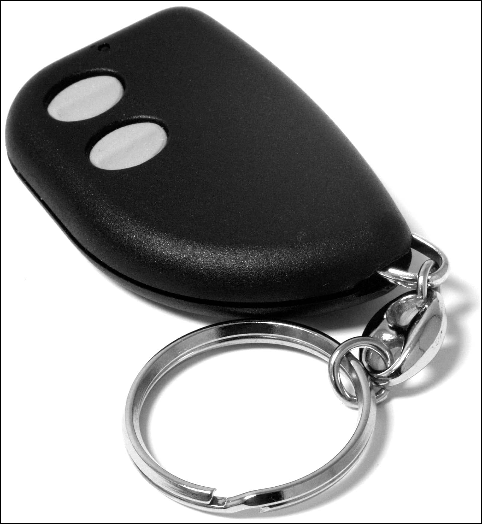
Click to zoom
Application Details
- Equipment Class
- DSC - Part 15 Security/Remote Control Transmitter
- Date of Grant
- Apr 05, 2004
- Application Purpose
- Original Equipment
- Date of Application
- Apr 05, 2004
- Equipment Note
- Remote Control
- Frequency Range
- 433.92000000 - 433.92000000
- Company
- Kone Industrial S.p.A
- Country
- Italy
Documents & Files
Document Text
Text extracted from the exhibit documents filed with the FCC. Open a document above to read the original.
Users Manual
TX1-HCS-433 TX2-HCS-433 TX3-HCS-433 User Manual Variazioni senza preavviso delle presenti informazioni non implicano responsabilità da parte AUREL. L’acquirente assume ogni responsabilità derivante dall’uso del prodotto. AUR°EL S.p.A. Via Foro dei Tigli, 4 - 47015 Modigliana (FC) – ITALY Rev. A, 16-01-2001 Tel.: +390546941124 – Fa x: +390546941660 Pag 1 of 3 http://www.aurel.it - email: [email protected] RF SAW Transmitter with HCS301 Encoder Small dimension hand-held RF transmitter with HCS301 rolling code encoder. How to use By pressing and releasing one of the available push buttons (according to model) a code transmission shall take place, through the related channel. Battery replacement When the LED light emission is feeble, the battery has to be replaced. Remove then the screw at the back of the radio transmitter and carefully open the plastic shell; discard the old battery and fit the new one (mod. V23A, 12 V) paying attention not to invert the polarity. Set back the transmitter cover with care in order not to damage the integrated circuit. Do not waste the old battery in the ambient but place it in the specially provided containers in order to facilitate its disposal. Available models TX1-HCS-433: 1 p/button pocket transmitter TX2-HCS-433: 2 p/buttons pocket transmitter TX3-HCS-433: 3 p/buttons pocket transmitter Key ring: optional Back shell tightening screw Data transmission led Ch 3 p/button Mod. TX3-HCS-433 Ch 1 p/button Ch 2 p/button TX back view Positive pole [+] Negative pole [-] TX1-HCS-433 TX2-HCS-433 TX3-HCS-433 User Manual Variazioni senza preavviso delle presenti informazioni non implicano responsabilità da parte AUREL. L’acquirente assume ogni responsabilità derivante dall’uso del prodotto. AUR°EL S.p.A. Via Foro dei Tigli, 4 - 47015 Modigliana (FC) – ITALY Rev. A, 16-01-2001 Tel.: +390546941124 – Fax: +390546941660 Pag 2 of 3 http://www.aurel.it - email: [email protected] CE Reference Inside the front half of the transmitter plastic shell, there is a label which contains the device identification data (product name, manufacturer, feed voltage and power consumption). Technical features Min Typ Max Unit Frequency 433.92 ± 0.15 MHz Emitted radio power –5 dBm Modulation OOK (On Off Keying) Power consumption 10 mA Operating Temperature -10 +55 °C Dimensions 56.5 x 36 x 14 mm Regulations compliance The TX1 -HCS -433, TX2-HCS -433 and TX3-HCS-433 radiotransmitters comply with European Regulations EN 300 220, EN 301 489 and EN 60950. The technical reports have been issued by PRIMA RICERCA & SVILUPPO (*) laboratory. (*) PRIMA RICERCA & SVILUPPO – via Campagna, 58 – 22020 Gaggino Faloppio (CO) – Italy. Inner view ot the transmitter front shell External view of the transmitter back shell [External] [Internal] INFORMATION TO USER This device complies with Part 15 of the FCC Rules. Operation is subject to the following two conditions: (1) This device may not cause harmful interference, and (2) This device must accept any interference received, including interference that may cause undesired operation. This equipment has been tested and found to comply with the limits for Class B Digital Device, pursuant to Part 15 of the FCC Rules. These limits are designed to provide reasonable protection against harmful interference in a residential installation. This equipment generates and can radiate radio frequency energy and, if not installed and used in accordance with the instructions, may cause harmful interference to radio communications. However, there is no guarantee that interference will not occur in a particular installation. If this equipment does cause harmful interference to radio or television reception, which can be determined by turning the equipment off and on, the user is encouraged to try to correct the interference by one or more of the following measures. • Reorient or relocate the receiving antenna • Increase the separation between the equipment and receiver • Connect the equipment into an outlet on a circuit different from that to which the receiver is connected • Consult the dealer or an experienced radio/TV technician for help Any changes or modifications not expressly approved by the party responsible for compliance could void the user’s authority to operate the equipment. TX1-HCS-433 TX2-HCS-433 TX3-HCS-433 User Manual Variazioni senza preavviso delle presenti informazioni non implicano responsabilità da parte AUREL. L’acquirente assume ogni responsabilità derivante dall’uso del prodotto. AUR°EL S.p.A. Via Foro dei Tigli, 4 - 47015 Modigliana (FC) – ITALY Rev. A, 16-01-2001 Tel.: +390546941124 – Fax: +390546941660 Pag 3 of 3 http://www.aurel.it
Cover Letter(s)
Response to TCB Findings 1. Please supply an operational description of the device. Supplied. 2. Please confirm that fresh batteries have been used during all testing. Yes, fresh batteries were used. 3. Has the device been tested on 3 orthogonal planes? Yes, device was tested on 3 orthogonal planes. 4. The RBW used for 20dB bandwidth measurement is not wide enough per ANSI C63.4 Clause 13.1.7. Please supply data with sufficient resolution bandwidth. Supplied.
Cover Letter(s)
Dept. R&D ( RES ) Sender: Nicola Bagnalasta Contact: +390233952517 [email protected] Attn: Reviewing Engineer Federal Communication Commission 7435 Oakland Mills Road Columbia MD 21046 USA Pero, April 02, 2004 Subject: CONFIDENTIALITY REQUEST FOR TX2 HCS-433 and TX3 HCS-433 FCC ID: RUI806950 This letter serves as an official request for confidentiality under FCC Rule Section 0.459. We have requested that the schematic diagrams, board layout, board component assembly, components part list & functional description required to be submitted with this application be withheld from public review. The documents are manufacturer company proprietary, the information could never get into the possession of our competitor Please contact me if there is any information you may need. Sincerely, Nicola Bagnalasta KONE Industrial S.p.A. Tel +390233952.1 - +390233923.1 Via Figino,41 Reg. Impr. Mi – C.F.e PIVA 0416024096 20016 Pero (MI) - Italy
ID Label/Location Info
DENOMINAZIONE CIRCUITO DIS. CONTR. APPR. DATA SCALA REV. A Disegno di proprietà della AUR°EL Senza autorizzazione è vietato comunicarlo a terzi e realizzarlo PER LE QUOTE PRIVE DI TOLLERANZA QUALITA IT Cod. Doc . : 1 2 3 4 5 6 7 8 9 A B C D E F G H I L M N O P Q R SPECIFICHE di INCISIONE LASER Poggi M. S.p.A. Tel. 0546-941124 Fax. 941660 MATERIALE --/-- Tavola Corrente Velocità File Frequenza 050400---IL 18/02/0414/10/03 KIT KONE RETRO
Test Report
Master:PT15-Sub-C-15231 Date: November 12, 2001 Test Report: 4W06996, Issue 2 Applicant: Kone Industrial S.p.A. Via Figino 41 Pero, 20016 Italy Equipment Under Test: TX3-HCS-433, TX2-HCS-433 Wireless Transmitters (EUT) FCC ID: RUI806950 In Accordance With: FCC Part 15, Subpart C, 15.231 Tested By: Nemko Canada Inc. 303 River Road, R.R. 5 Ottawa, Ontario K1V 1H2 Authorized By: Glen Westwell, Wireless Technologist Date: 17 March 2004 Total Number of Pages: 17 Nemko Canada Inc. FCC PART 15, SUBPART C, 15.231 PROJECT NO.:4W06996, Issue 2 EQUIPMENT: TX3-HCS-433, TX2-HCS-433 Wireless Transmitters Page 2 of 17 Table of Contents Section 1. Summary of Test Results ...................................................................................3 Section 2. Equipment Under Test .......................................................................................5 Section 3. Transmission Requirements ..............................................................................6 Section 4. Radiated Emissions .............................................................................................9 Section 5. Occupied Bandwidth ........................................................................................14 Section 6. Block Diagrams .................................................................................................16 Section 7. Test Equipment List ..........................................................................................17 Nemko Canada Inc. FCC PART 15, SUBPART C, 15.231 PROJECT NO.:4W06996, Issue 2 EQUIPMENT: TX3-HCS-433, TX2-HCS-433 Wireless Transmitters Page 3 of 17 Section 1. Summary of Test Results General All measurements are traceable to national standards. These tests were conducted on a sample of the equipment for the purpose of demonstrating compliance with Part 15, Subpart C. All tests were conducted using measurement procedure ANSI C63.4-1992. Radiated emissions are made on an open area test site. A description of the test facility is on file with the FCC. THIS TEST REPORT RELATES ONLY TO THE ITEM(S) TESTED. THE FOLLOWING DEVIATIONS FROM, ADDITIONS TO, OR EXCLUSIONS FROM THE TEST SPECIFICATIONS HAVE BEEN MADE. See “ Summary of Test Data”. TESTED BY: ______________________________ DATE: 9 March 2004 Kevin Carr, EMC/EMI/Wireless Specialist TESTED BY: ______________________________ DATE: 9 March 2004 Daxesh Thakker, Wireless Test Engineer Nemko Canada Inc. authorizes the above named company to reproduce this report provided it is reproduced in its entirety and for use by the company’s employees only. Any use which a third party makes of this report, or any reliance on or decisions to be made based on it, are the responsibility of such third parties. Nemko Canada Inc. accepts no responsibility for damages, if any, suffered by any third party as a result of decisions made or actions based on this report. This report applies only to the items tested. This report shall not be reproduced except in full without the written approval of the testing laboratory. Nemko Canada Inc., a testing laboratory, is accredited by the Standards Council of Canada. The tests included in this report are within the scope of this accreditation. Nemko Canada Inc. FCC PART 15, SUBPART C, 15.231 PROJECT NO.:4W06996, Issue 2 EQUIPMENT: TX3-HCS-433, TX2-HCS-433 Wireless Transmitters Page 4 of 17 Summary Of Test Data Name of Test Para. Number Results Transmission Requirements 15.231(a) Complied Radiated Emissions 15.231(b) Complied Occupied Bandwidth 15.231(c) Complied Frequency Tolerance 15.231(d) N/A(1) Periodic Alternate Field Strength Requirements 15.231(e) N/A(2) Powerline Conducted Emissions 15.207 N/A(3) N/A(1) – The EUT does not transmit within the 40.66 – 40.70 MHz band. N/A(2) – The Applicant is not applying for this section of the standard N/A(3) – The Eut is battery operated Test Conditions: Indoor Temperature: 24°C Humidity: 2% Outdoor Temperature: 8°C Humidity: 54% Nemko Canada Inc. FCC PART 15, SUBPART C, 15.231 PROJECT NO.:4W06996, Issue 2 EQUIPMENT: TX3-HCS-433, TX2-HCS-433 Wireless Transmitters Page 5 of 17 Section 2. Equipment Under Test General Equipment Information Manufacturer: Kone Industrial S.p.A. Via Figino, 41 Pero, 20016 Italy Model No.: TX3-HCS-433, TX2-HCS-433 Serial No.: None Date Received In Laboratory: 3 Feb. 2004 Nemko Identification No.: 1, 2, 3, 4 Tunable Bands: 1 Number of Channels: Fixed frequency. 433.92MHz Channel Spacing: N/A, fixed frequency User Frequency Adjustment: None Type of Modulation: OOK (ON Off Keying) Power Source: One “23AE 12V” Battery Nemko Canada Inc. FCC PART 15, SUBPART C, 15.231 PROJECT NO.:4W06996, Issue 2 EQUIPMENT: TX3-HCS-433, TX2-HCS-433 Wireless Transmitters Page 6 of 17 Section 3. Transmission Requirements Para. No.: 15.231(a) Test Performed By: Kevin Carr Date of Test: 11 Feb 04 Minimum Standard: 15.231(a) Continuous transmissions such as voice, video or data transmissions are not permitted. 15.231(a)(1) A manually operated transmitter shall employ a switch that will automatically deactivate the transmitter within not more than 5 seconds after being released. 15.231(a)(2) A transmitter activated automatically shall cease transmission within 5 seconds of activation. 15.231(a)(3) Periodic transmissions at regular pre-determined intervals are not permitted. However polling or supervisory transmissions to determine system integrity of transmitters used in security or safety applications are allowed if the periodic rate of transmission does not exceed one transmission of not more than one second duration per hour for each transmitter. 15.231(a)(4) Intentional radiators which are employed for radio control purposes during emergencies involving fire, security, and safety of life, when activated to signal an alarm, may operate during the pendency of the alarm. Test Results: Complied. Test Data: Compliance was determined by verification of technical specifications and a functional test on the equipment. Nemko Canada I…
Text truncated - open the document above for the full version.
Contact Information
Applicant
Nicola Bagnalasta(Project Engineer)
Test Firm
Nemko Canada Inc.Stuart Beck
Technical Specifications
| # | Rule Parts | Frequency Range | Power Output |
|---|---|---|---|
| 1 | 15.231 | 433.92 MHz - 433.92 MHz | - |