RUZ-031Permalog+ PR4US Leak Detector
HWM-Water Ltd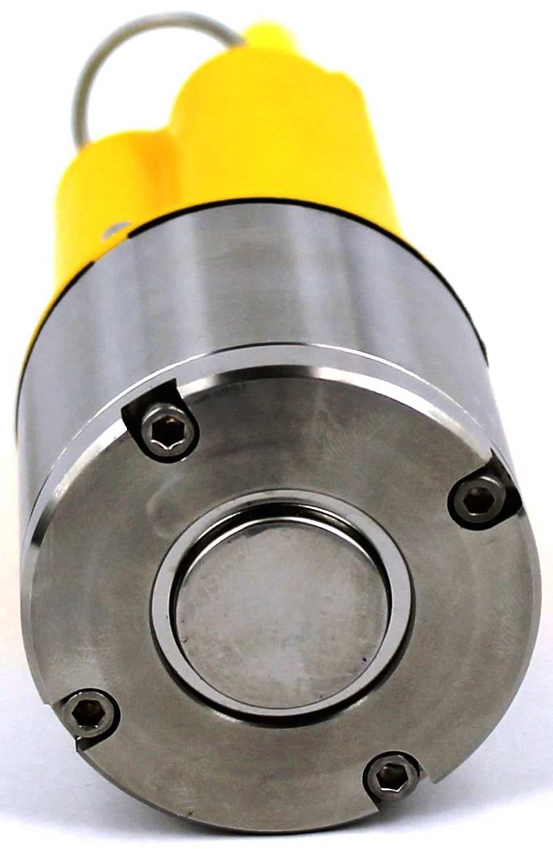
Click to zoom
Application Details
- Equipment Class
- DXX - Part 15 Low Power Communication Device Transmitter
- Date of Grant
- Apr 16, 2013
- Application Purpose
- Original Equipment
- Date of Application
- Apr 16, 2013
- Equipment Note
- Permalog+ PR4US Leak Detector
- Frequency Range
- 914.47000000 - 914.47000000
- Company
- HWM-Water Ltd
- Country
- United Kingdom
Documents & Files
Document Text
Text extracted from the exhibit documents filed with the FCC. Open a document above to read the original.
Users Manual
Permalog Plus User Manual HWM-Water Ltd Ty Coch House Llantarnam Park Way Cwmbran Permalog Plus User Manual NP44 3AW United Kingdom MAN-031-0001 Issue C Tel: +44 (0) 1633 489479 Date 14/03/13 Fax: +44 (0) 1633 877857 Email: [email protected] Updated by AC Web: www.hwm-water.com 2 Contents Contents Page 2 Introduction Page 3 Benefits of Use Page 4 Warnings Page 5 Important Notes Page 6 Permalog Plus Features Page 7 Deployment Page 8 Redeployment Page 8 User Interface Page 9 Technical Specification Page 11 Contact Page 12 Permalog® Plus — Local Thinking, Global Capabilities 3 Introduction Permalog® Plus is the very latest in a highly successful line of permanent and semi- permanent leak noise loggers. This logger can be used as both a traditional leak noise logger, and as a "drive by" logger. Permalog® Plus leak noise loggers are deployed throughout the water distribution net-work to provide continuous surveying of leakage. Each Permalog® Plus unit adapts itself automatically to its environment. If no leak is present a signal is transmitted to indicate normal background conditions, however, as soon as a possible leak is detected, the Permalog® Plus unit enters an alarm state and transmits a signal to indicate a leak condition. The logger also incorporates an LED to display the leak status visually. Following a rise in unaccounted for water, or at standard intervals, a leakage patrol is carried out in the area using the Permalog® Patroller module. Leak status information from the loggers is displayed on the PDA screen of the Patroller module and stored in the memory. With no cables or hard installation, Permalog® Plus is simply fitted to a metal fixture within the chamber (usually a hydrant or valve) and left alone. Logging times, Patrol times and Transmission times are fully customisable ensuring the operator gets the most benefit from the system and can configure it to their advantage. With integrated Bluetooth technology, the Permalog® Plus logger offers easy management through the PDA and Patroller Interface Unit. Permalog® Plus can be fully configured without having to be removed from the chamber. Permalog® Plus — Local Thinking, Global Capabilities 4 Benefits of Use Operational Benefits • 100% of distribution system permanently monitored. • Finds more leaks more quickly than traditional methods. • Responds rapidly to new mains bursts, improving service to customers. • Automates and de-skills leak surveying, eliminating human error and finding leaks that would otherwise be missed. • Eliminates "stop tap bashing" (surveying using listening sticks). • Operates independently of the size, structure or integrity of the area being monitored. • Completely non-invasive method with no detrimental effects on supply to customers (preferred alternative to step testing). • Improves overall detection efficiency and motivation by enabling skilled staff to concentrate on finding "known" leaks and avoid wasting time in no-leak areas. • Operates continuously for up to 5 years (dependant on configuration), enabling a low leakage level to be maintained easily. • Bluetooth and RF technology allow wireless configuration on site. • Logging can be fully customised to fit customer’s requirements. Economic Benefits • Survey costs cut by >90% with elimination of surveying using listening sticks • Dramatic productivity gain - one person can survey several DMA's (District Metered Areas) per day. • Record low leakage levels attainable and easily maintained. • Low installation cost and no maintenance costs enable rapid payback, with in- creasing profits per year. • No night work required for leak surveying. • Negligible incremental cost of additional surveys. • Highly attractive return on capital employed. • Lower leakage level reduces cost of water into supply. • Demonstrates high technology benefits to regulator, customers, shareholders and international clients. With over 200,000 units deployed worldwide, it’s easy to see why the Permalog range is one of the most highly respected Leak Noise Loggers in the industry. HWM-Water Ltd, your gateway to the latest technology, solutions and services. Permalog® Plus — Local Thinking, Global Capabilities 5 Warnings Canadian warning statement "Under Industry Canada regulations, this radio transmitter may only operate using an antenna of a type and maximum (or lesser) gain approved for the transmitter by Industry Canada. To reduce potential radio interference to other users, the antenna type and its gain should be so chosen that the equivalent isotropically radiated power (e.i.r.p.) is not more than that necessary for successful communication." "This device complies with Industry Canada licence-exempt RSS standard(s). Operation is subject to the following two conditions: (1) this device may not cause interference, and (2) this device must accept any interference, including interference that may cause undesired operation of the device." "Conformément à la réglementation d'Industrie Canada, le présent émetteur radio peut fonctionner avec une antenne d'un type et d'un gain maximal (ou inférieur) approuvé pour l'émetteur par Industrie Canada. Dans le but de réduire les risques de brouillage radioélectrique à l'intention des autres utilisateurs, il faut choisir le type d'antenne et son gain de sorte que la puissance isotrope rayonnée équivalente (p.i.r.e.) ne dépasse pas l'intensité nécessaire à l'établissement d'une communication satisfaisante." "Le présent appareil est conforme aux CNR d'Industrie Canada applicables aux appareils radio exempts de licence. L'exploitation est autorisée aux deux conditions suivantes : (1) l'appareil ne doit pas produire de brouillage, et (2) l'utilisateur de l'appareil doit accepter tout brouillage radioélectrique subi, même si le brouillage est susceptible d'en compromettre le fonctionnement." FCC warning statement: • This device complies with Part 15 of the FCC Rules. Operation is subject to the following two conditions: (1) This device may not…
Text truncated - open the document above for the full version.
Cover Letter(s)
TRL 51F050 iss04 REQUEST FOR CONFIDENTIALITY IN ACCORDANCE WITH FCC RULE 0.459 Date 22/03/2013 TRaC GLOBAL LTD. 100 Frobisher Business Park Malvern Worcestershire WR14 1BX UK RE: Certification Application FCC ID: RUZ-031 To Whom It May Concern: Please be advised that the following information is to be held confidential on behalf of HMW-Water Ltd. BL-031-0001-F (Permalog+ battery PCB) BL-061-0003 B - AMRLOG Main PCB BL-061-0003-B P+ AMRLOG Main BL-061-0004-B (AMRLOG Radio Circuit) BL-061-0004-B P+ AMRLOG Radio BP-031-0001-L (Permalog+ battery PCB) BP-061-0003-D (AMRLOG Main PCB) BP-061-0004 -D (AMRLOG Radio Circuit) GP-031-0001-F(Permalog Plus) SE-031-0001-F (Permalog+ battery PCB) SE-061-0003 B AMRLOG Main Circuit SE-061-0004-B (AMRLOG Radio Circuit) Internal Photos.pdf Permalog+ Block Dia and Tech Desc The application contains technical information which Applicants Name Here deems to be trade secrets and propriety. If made public, the information might be used to the disadvantage of the applicant in the market place. Thank you for your attention to this matter. Yours faithfully HWM-Water Ltd Signature Full Name: David Hicks HWM-Water Ltd Ty Coch House Llantarnam Park Way Cwmbran NP44 3AW United Kingdom Tel: +44 (0) 1633 489 479 Fax: +44 (0) 1633 877 857 Web: www.hwm-water.com
Cover Letter(s)
TRL 51F050 iss04 REQUEST FOR CONFIDENTIALITY INTERNAL PHOTOS Date 16/04/2013 TRaC GLOBAL LTD. 100 Frobisher Business Park Malvern Worcestershire WR14 1BX UK RE: Certification Application FCC ID: RUZ-031 To Whom It May Concern: Please be advised that the internal photos are to be held confidential on behalf of HWM-Water Ltd, the products is only serviceable by the grantee or designated technical party. The product is a sealed, non- consumer device that has potted (epoxy resin) battery PCB in the plastic housing. Thank you for your attention to this matter. Yours faithfully HWM-Water Ltd Signature Full Name: David Hicks HWM-Water Ltd Ty Coch House Llantarnam Park Way Cwmbran NP44 3AW United Kingdom Tel: +44 (0) 1633 489 479 Fax: +44 (0) 1633 877 857 Web: www.hwm-water.com
External Photos
PR4US External Photographs
ID Label/Location Info
An example of what the PC screen will look like at this stage Step 1 of 13 Step 4 of 13 Step 7 of 13 Step 2 of 13 Step 5 of 13 Step 8 of 13 Step 3 of 13 Step 6 of 13 Step 9 of 13 Connect the aerial located in the P+ test chamber u ntil finger tight. Swipe a magnet over the Permalog + reed switch in t he location shown. Check the lights flash green and red in the location shown Using the Permalog PC. Select ‘QM TestPer’ icon from the desk- top. In the Manual entries column, select ‘Load order’ Select the required SOA number for the order from t he list then select ‘Open’ Close the chamber door and press the ‘space bar’ on the keyboard. In this instance space is selecting ‘LEDs OK’ Once the Automated Tests are completed the whole of section 3 will become orange. Press the space bar (in this instanc e it is selecting confirm button in the Post-Test section of the form ) Upon completion of post test a serial number will b e printed Select the required region from the ‘Initial Comms Frequency’ Observe precautions for handling electrostatic devices at all times The test will have now begun, each of the white box es will turn orange upon passing the test. A yellow box indicates the t est that is currently in Progress and a red box shows a fail 100% 0% Work Instruction Permalog + - Programming and Test WI-031-0108-A Photograph used only for the LED Location Reed switch location Aerial Connected P+ Test chamber closed Permalog onto the vibration table Place the Permalog + onto the vibration table in th e P+ Test Chamber. Press the space bar on the keyboard (in th is instance it selects the confirmed button) Issue Date PCN Drawn Checked Approved Modification Summary A 19/03/13 4567 MP Permalog + test and programmin g REVISION / APPROVAL HISTORY This symbol highlights a QUALITY critical build poi nt. Extra care must be taken wherever this symbol is us ed This symbol highlights a SAFETY critical build poin t. Extra care must be taken wherever this symbol is us ed. Please note that the following procedure is only to be completed by authorised and approved personnel of Halma Water Management. Work Instruction Permalog + - Programming and Test WI-031-0108-A Step 10 of 13 Step 13 of 13 Step 11 of 13 Step 12 of 13 Work Instruction Permalog + - Programming and Test WI-031-0108-A If the product is being sent to the US apply an FCC label. If the product is being sent to the EU apply a CE label, e lse apply no label here. Refer to WI-031-0107 on how to apply the hook to the housing. Remove the Permalog + from the test chamber. Apply a Permalog Plus label ( LAB4200 ) in the location shown Apply the serial number to the base of the Permalog + in the location shown 100% 0% Observe precautions for handling electrostatic devices at all times American FCC Label applied to the Permalog + European CE Label applied to the Permalog + Apply an aerial cap ( HDW4130 ) to the aerial connector
Test Report
A RADIO TEST REPORT FOR HWM-WATER Ltd ON PR4US DOCUMENT NO. TRA-012696-47-00-A Total number of pages: 31 TRaC Wireless Test Report : TRA-012696-47-00-A Applicant : HWM-Water Ltd Apparatus : PR4US Specification(s) : CFR47 Part 15.249 & RSS-210 Annex 2 A2.9 Purpose of Test : Certification FCCID : RUZ-031 Certification Number : 10962A-031 Authorised by : : Radio Product Manager Issue Date :14 th March 2013 Authorised Copy Number : PDF TRaC Global Test Report: TRA-012696-47-00-A Contents Section 1: Introduction 4 1.1 General 4 1.2 Tests Requested By 5 1.3 Manufacturer 5 1.4 Apparatus Assessed 5 1.5 Test Result Summary 6 1.6 Notes Relating To The Assessment 7 1.7 Deviations from Test Standards 7 Section 2: Measurement Uncertainty 8 2.1 Measurement Uncertainty Values 8 Section 3: Modifications 10 3.1 Modifications Performed During Assessment 10 Appendix A: Formal Emission Test Results 11 A1 Transmitter Intentional Emission Radiated 12 A2 Radiated Electric Field Emissions 13 Appendix B: Supporting Graphical Data 15 Appendix C: Additional Test and Sample Details 19 Appendix D: Additional Information 25 Appendix E: Calculation of the duty cycle correction factor 26 Appendix F: Photographs and Figures 27 Appendix G: MPE Calculation 30 3 TRaC Global Test Report: TRA-012696-47-00-A Section 1: Introduction 1.1 General This report contains an assessment of an apparatus against Electromagnetic Compatibility Standards based upon tests carried out on samples submitted to the Laboratory. Test performed by: TRaC Global [ ] Unit E South Orbital Trading Park Hedon Road Hull, HU9 1NJ. United Kingdom. Telephone: +44 (0) 1482 801801 Fax: +44 (0) 1482 801806 TRaC Global [X] Unit 1 Pendle Place Skelmersdale West Lancashire, WN8 9PN United Kingdom Telephone: +44 (0) 1695 556666 Fax: +44 (0) 1695 577077 Email: [email protected] Web site: http://www.tracglobal.com Tests performed by: D. Winstanley Report author: D. Winstanley This report must not be reproduced except in full without prior written permission from TRaC Global. 4 TRaC Global Test Report: TRA-012696-47-00-A 1.2 Tests Requested By This testing in this report was requested by : HWM-Water Ltd Ty Coch House Llantarnam Industrial Park Cwmbran NP44 3AW 1.3 Manufacturer As Above 1.4 Apparatus Assessed The followin g apparatus was assessed between 27 th – 28 th February 2013 PR4US The PR4US is a transmitter operating at 914.5 MHz 5 TRaC Global Test Report: TRA-012696-47-00-A 1.5 Test Result Summary Full details of test results are contained within Appendix A. The following table summarises the results of the assessment. The statements relating to compliance with the standards below apply ONLY as qualified in the notes and deviations stated in sections 1.6 to 1.7 of this test report. Full details of test results are contained within Appendix A. The following table summarises the results of the assessment. Regulation Test Type Title 47 of the CFR: Part 15 Subpart (c) RSS-210 Issue 8 RSS-Gen Issue 3 Measurement standard Result Spurious Emissions Radiated <1000MHz 15.209 & 15.249 (a) (d) Annex 2 A2.9(a) RSS-Gen 4.9 ANSI C63.10:2009 Pass Spurious Emissions Radiated >1000MHz 15.209 & 15.249 (a) (d) Annex 2 A2.9(a) RSS-Gen 4.9 ANSI C63.10:2009 Pass AC Power conducted emissions 15.207 RSS-Gen 7.2.4 ANSI C63.10:2009 N/A Intentional Emission Frequency 15.249 (a) Annex 2 A2.9(a) ANSI C63.10:2009 Pass Intentional Emission Field Strength 15.249 (a) RSS-Gen 4.8 ANSI C63.10:2009 Pass Intentional Emission Band Occupancy 15.215 (c) RSS-Gen 4.6 ANSI C63.10:2009 Pass Intentional Emission ERP (mW) - RSS-Gen 4.8 ANSI C63.10:2009 N/A Unintentional Radiated Spurious Emissions 15.109 RSS-Gen 4.10 ANSI C63.10:2009 N/A Antenna Arrangements Integral: 15.203 RSS-Gen 7.1.2 - Pass Antenna Arrangements External Connector 15.204 RSS-Gen 7.1.2 - N/A Restricted Bands 15.205 RSS-Gen 7.2.2 - - Maximum Frequency of Search 15.33 RSS-Gen 4.9 - - Extrapolation Factor 15.31(f) RSS-Gen 7.2.7 - - Abbreviations used in the above table: ANSI C 63.10:2009 is outside the scope of the laboratories UKAS accreditation. CFR : Code of Federal Regulations ANSI : American National Standards Institution REFE : Radiated Electric Field Emissions PLCE : Power Line Conducted Emissions 6 TRaC Global Test Report: TRA-012696-47-00-A 1.6 Notes Relating To The Assessment With regard to this assessment, the following points should be noted: The results contained in this report relate only to the items tested and were obtained in the period between the date of initial receipt of samples and the date of issue of the report. The apparatus was set up and exercised using the configurations, modes of operation and arrangements defined in this report only. Particular operating modes, apparatus monitoring methods and performance criteria required by the standards tested to have been performed except where identified in Section 1.7 of this test report (Deviations from Test Standards). For emissions testing, throughout this test report, “Pass” indicates that the results for the sample as tested were below the specified limit (refer also to Section 2, Measurement Uncertainty). Where relevant, the apparatus was only assessed using the monitoring methods and susceptibility criteria defined in this report. All testing with the exception of testing at the Open Area Test Site was performed under the following environmental conditions: Temperature : 17 to 23 C Humidity : 45 to 75 % Barometric Pressure : 86 to 106 kPa All dates used in this report are in the format dd/mm/yy. This assessment has been performed in accordance with the requirements of ISO/IEC 17025. 1.7 Deviations from Test Standards There were no deviations from the standards test ed to. 7 TRaC Global Test Report: TRA-012696-47-00-A Section 2: Measurement Uncertainty 2.1 Measurement Uncertainty Values For the test data recorded the following measurement uncertainty was calculated: Radio Testing – General Uncertainty Schedule All statements of uncertainty are expanded standard…
Text truncated - open the document above for the full version.
Contact Information
Applicant
Andy Earp(Product Validation Manager)
Test Firm
Element Materials Technology Warwick LtdStewart Barrowclough
Technical Specifications
| # | Rule Parts | Frequency Range | Power Output |
|---|---|---|---|
| 1 | 15C | 914.47 MHz - 914.47 MHz | - |
Other Applications from HWM-Water Ltd

RUZ-154
Jan 22, 2020Data logger interface with Bluetooth
Equipment Class
DXX - Part 15 Low Power Communication Device Transmitter
RUZ-485
Aug 04, 2013Ecochirp
Equipment Class
TNB - Licensed Non-Broadcast Station Transmitter