RVEVEHICLEMCOMLow Power Transmitter
ASYST Shinko, Inc.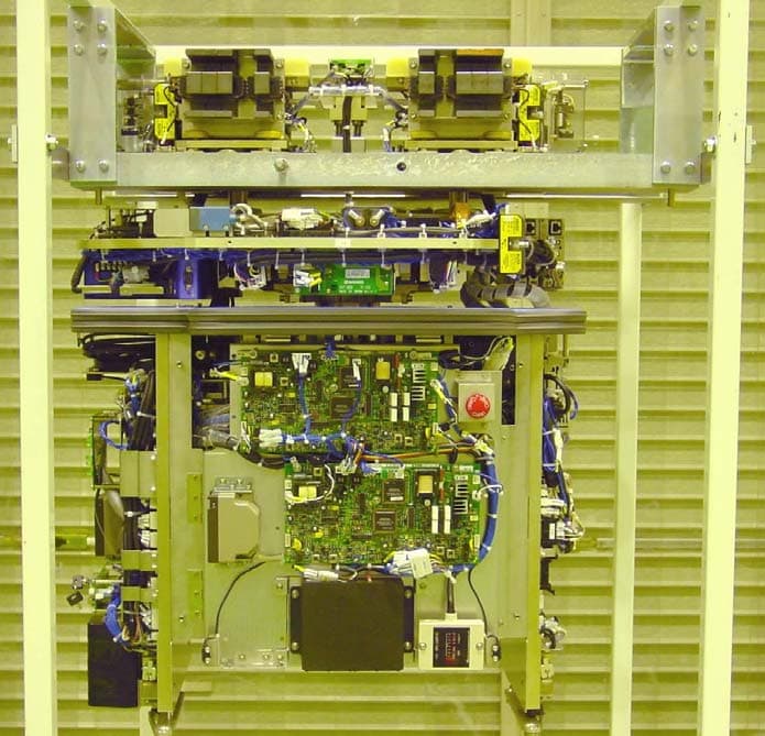
Click to zoom
Application Details
- Equipment Class
- DCD - Part 15 Low Power Transmitter Below 1705 kHz
- Date of Grant
- Mar 23, 2004
- Application Purpose
- Original Equipment
- Date of Application
- Mar 23, 2004
- Equipment Note
- Low Power Transmitter
- Frequency Range
- 0.35325000 - 0.35325000
- Company
- ASYST Shinko, Inc.
- Country
- Japan
Documents & Files
Document Text
Text extracted from the exhibit documents filed with the FCC. Open a document above to read the original.
Users Manual
ASYST-SHINKO,INC. AD-03-0218 Rev.0 Vehicle Communication Unit MCOM Operation Manual i System operation manual of Vehicle Communication Unit MCOM AD-03-0218 Revision 0 The information furnished herein by ASYST SHINKO, INC. is proprietary and confidential to ASYST SHINKO, INC. personnel and is not to be duplicated, published, or disclosed to any third party in whole or in part without permission from ASYST SHINKO, INC. Copyright © 2002 ASYST SHINKO, INC. ALL RIGHTS RESERVED. Unpublished rights reserved under the copyright laws of the United States. ASYST-SHINKO,INC. AD-03-0218 Rev.0 Vehicle Communication Unit MCOM Operation Manual ii The information contained herein is provided pursuant to the terms of a License, Non-disclosure and/or Confidentiality Agreement and constitutes and contains valuable proprietary information and trade secrets of ASYST SHINKO, INC., embodying substantial creative efforts and confidential information, ideas, and expressions. Accordingly, strict compliance with the terms and conditions of the governing Agreement, including, without limitation, all restrictions on use and disclosure, is required as a condition to the use of the information contained herein. Except as may be permitted in the applicable Agreement, the information herein may not be reproduced or disclosed in whole or in part. Restricted Rights Legend Use, duplication, or disclosure by the Government is subject to restrictions as set forth in subparagraph <c> (1) (ii) of the Rights in Technical Data and Computer Software clause at DFARS 252.277-7013. ASYST SHINKO, INC. 100 Takegahana, Ise city, Mie prefecture, 516-0005, Japan Telephone: +81-596-36-2335 Facsimile: +81-596-36-2162 ASYST-SHINKO,INC. AD-03-0218 Rev.0 Vehicle Communication Unit MCOM Operation Manual iii Revision History Rev. Monthly/Day/Year Description Author 0 Feb. 27, 2004 The first edition(Preliminary) M.Kuroda 1 ASYST-SHINKO,INC. AD-03-0218 Rev.0 Vehicle Communication Unit MCOM Operation Manual iv Contents 1. Introduction................................................................................ 1 1.1. Application.................................................................................................................... 1 1.2. Related Rules, Laws................................................................................................ 1 1.3. Abbreviations............................................................................................................... 1 2. Safety........................................................................................ 2 2.1. Alert Boxes................................................................................................................... 2 2.1.1. General................................................................................................................................2 2.1.2. Definitions of DANGER, WARNING and CAUTION................................2 2.1.3. Precautions on use......................................................................................................3 2.1.4. Storage................................................................................................................................3 2.1.5. Installation..........................................................................................................................4 2.1.6. Maintenance and Inspection..................................................................................4 3. Outline of the Vehicle communication unit MCOM..................... 5 3.1. Overview....................................................................................................................... 5 3.2. MCOM configuration................................................................................................ 6 3.3. Function of each unit................................................................................................ 8 3.3.1. M-COM2 (Printed circuit board )........................................................................................8 3.3.2. COM-TR (power line COmmunication TRansformer)........................................................9 3.3.3. IND-TR (INDuction line communication TRansformer).......................................................9 3.4. FCC standard............................................................................................................ 11 3.5. Control/modulating of communication............................................................. 12 3.5.1. Power line communication.....................................................................................12 3.5.2. Induction line communication..............................................................................13 4. Specification............................................................................ 14 4.1. Input/Output............................................................................................................... 14 4.2. Specification.............................................................................................................. 16 4.2.1. M-COM2...........................................................................................................................16 4.2.2. CMC-TR............................................................................................................................16 4.2.3. IND-TR...............................................................................................................................16 5. Error process........................................................................... 17 6. Cautions on Use...................................................................... 18 Introduction ASYST-SHINKO,INC. AD-03-0218 Rev.0 Vehicle Communication Unit MCOM Operation Manual 1 1. Introduction 1.1. Application This document describes the operation of communication unit for transport system, OHT, OHS, etc. 1.2. Related Rules, …
Text truncated - open the document above for the full version.
External Photos
External Photo FCC ID: RVEVEHICLEMCOM ASYST SHINKO, INC. COM-TR and IND-TR inside of VEHICLE COM-TR IND-TR MCOM2 MCOM Unit inside of VEHICLE
Internal Photos
Internal Photo FCC ID: RVEVEHICLEMCOM ASYST SHINKO, INC. Module (Front side of MCOM-2) Module (Back side of MCOM-2) Internal Photo FCC ID: RVEVEHICLEMCOM ASYST SHINKO, INC. IND-TR Transformer for Induction line communication)
Test Report
Test report No. : 24GE0078-HO-1 FCC ID : RVEVEHICLEMCOM Page : 2 of 18 Issued date : February 20, 2004 UL Apex Co., Ltd. Yokowa EMC Lab. 108 Yokowa-cho, Ise-shi, Mie-ken, 516-1106 JAPAN Telephone: +81 596 39 1485 Facsimile: +81 596 39 0232 MF060b(10.04.03) CONTENTS PAGE SECTION 1: Client information 3 SECTION 2: Equipment under test (E.U.T.) 3 SECTION 3: Test specification, methods & procedures 5 SECTION 4: Operation of E.U.T. during testing 6 SECTION 5: Summary of test results 8 SECTION 6: Radiated emission 9 APPENDIX 1: Photographs of test setup 11 APPENDIX 2: Data of EMI test 12 APPENDIX 3: Test instruments 18 Test report No. : 24GE0078-HO-1 FCC ID : RVEVEHICLEMCOM Page : 3 of 18 Issued date : February 20, 2004 UL Apex Co., Ltd. Yokowa EMC Lab. 108 Yokowa-cho, Ise-shi, Mie-ken, 516-1106 JAPAN Telephone: +81 596 39 1485 Facsimile: +81 596 39 0232 MF060b(10.04.03) SECTION 1: Client information Company name : ASYST SHINKO, INC. Trade name : ASYST SHINKO Address : 100 Takegahana-cho, Ise-shi, Mie-ken, 516-0005 JAPAN Number : +81 596 36 1260 Facsimile Number : +81 596 36 0345 Contact Person : Mitsuyoshi Kuroda SECTION 2: Equipment under test (E.U.T.) 2.1 Identification of E.U.T. Type of Equipment : MCOM: Merge/diverge Communication Modem Model No. : MCOM Sample No. : MCOM-001 Condition of EUT : Production model Rating : DC 24V , DC 5V , DC + 12V Country of Manufacture : Japan Receipt Date of Sample : April 8, 2002 Test report No. : 24GE0078-HO-1 FCC ID : RVEVEHICLEMCOM Page : 4 of 18 Issued date : February 20, 2004 Revised date : March 3, 2004 UL Apex Co., Ltd. Yokowa EMC Lab. 108 Yokowa-cho, Ise-shi, Mie-ken, 516-1106 JAPAN Telephone: +81 596 39 1485 Facsimile: +81 596 39 0232 MF060b(10.04.03) 2.2 Product Description Model: MCOM, referred to as the EUT in this report, is a MCOM: Merge/diverge Communication Modem. The specification is as follows; Communication unit’s carrier frequency (Intentional Radiators) : 88.8kHz (on/off keying) : 353.25kHz two level FSK (342.9 kHz and 363.6 kHz) Communication unit’s main clock(Unintentional Radiators) : 24MHz 1) Power line communication *This power line is not for the Public utilities, but it is the standalone line for the Radio Communication. The communication unit CMC (C ommunication Modem Controller) is used for the communication between the ground Vehicle Controller and several vehicles in the conveyance system. The communication signals are overlaid onto the power line for non-conductive power supply to the vehicles. In some systems, a separate signal lines may be used. The communication unit MCOM (M erge/diverge Communication Modem) is used for the communication between vehicle and the ground Vehicle Controller. They modulates the signals sent from the Vehicle controller and transmits the modulated signals to the vehicles. It also demodulates the signals sent from the vehicles and transmits them to the Vehicle controller. The communication method in use is FSK ( frequency shift keying). The communication frequencies are as follows. From to Frequency (1) CMC(Tx) MCOM(Rx): 285.7 kHz and 315.8 kHz two level FSK (2) MCOM(Tx) CMC(Rx): 342.9 kHz and 363.6 kHz two level FSK *CMC is approved by FCC separately. 2) Induction line communication The communication unit MCOM (M erge/diverge Communication Modem) is used for the communication between vehicle and other Vehicle. MCOM outputs the detection signal of one bit in the controller when the existence of the signal which other vehicle transmitted. A Induction line is installed on both sides of the track. Therefore one transformer and circuit are each right and left, and they are equal. It can be changed if one transformer is used for the reception or it is used for the transmission. A left-right coil is combined with the loop line, and it can watch each other's transmitting signal. Then, a trouble such as the breakage of the transformer can be diagnosed. The communication method in use is Adoption of On Off Keying Method. The communication frequencies are 88.8kHz. *The evaluation of EUT : MCOM was carried out in the Test Report for FCC Part 15 Subpart B. Test report No. : 24GE0078-HO-1 FCC ID : RVEVEHICLEMCOM Page : 5 of 18 Issued date : February 20, 2004 UL Apex Co., Ltd. Yokowa EMC Lab. 108 Yokowa-cho, Ise-shi, Mie-ken, 516-1106 JAPAN Telephone: +81 596 39 1485 Facsimile: +81 596 39 0232 MF060b(10.04.03) SECTION 3: Test specification, methods & procedures 3.1 Test Specification Test Specification : FCC Part 15 Subpart C Section 15.209 : 2002 Title : FCC 47CFR Part15 Radio Frequency Device Subpart C Intentional Radiators Section 15.209 Radiated emission limits; general requirements 3.2 Methods & Procedures No. Item Te s t P ro c e du re Specification Remarks 1 Radiated emission ANSI C63.4:2001 Section 15.209(a) 3m 2 Conducted emission ANSI C63.4:2001 Section 15.207(a) LISN *UL Apex’s EMI Work Procedures No.QPM05. These tests were performed without any deviations from test procedure excluding below additions or deviations. 3.3 Exclusion from standards No. Item Te s t P ro c e d u re Specification Remarks 2 Conducted emission ANSI C63.4:2001 Section 15.207(a) LISN *1) The test is not applicable since the EUT does not have AC mains and is not designed to be connected to the public utility (AC) power line. Test report No. : 24GE0078-HO-1 FCC ID : RVEVEHICLEMCOM Page : 7 of 18 Issued date : February 20, 2004 UL Apex Co., Ltd. Yokowa EMC Lab. 108 Yokowa-cho, Ise-shi, Mie-ken, 516-1106 JAPAN Telephone: +81 596 39 1485 Facsimile: +81 596 39 0232 MF060b(10.04.03) Description of EUT and Support equipment No. Item Model number Serial number Manufacturer Remarks A MCOM MCOM MCOM-001 SHINKO EUT A8050628033 B M-COM2 3ASSYC807901 A8050628034 SHINKO SHINKO EUT C COM-TR(RX) 3CL520A011500-02 - SHINKO EUT D COM-TR(TX) 3CL520A011500-01 - SHINKO EUT E IND-TR 3CL520A011400 - SHINKO EUT F Vehicle VHT5-1 - SHINKO - G DC24V Power Supply PAB25-1TR 30081818 KIKUSUI - H Host - - SHINKO - *All the responsibility of manufacturing th…
Text truncated - open the document above for the full version.
Test Setup Photos
Test report No. : 24GE0078-HO-1 FCC ID : RVEVEHICLEMCOM Page : 11 of 18 Issued date : February 20, 2004 UL Apex Co., Ltd. Yokowa EMC Lab. 108 Yokowa-cho, Ise-shi, Mie-ken, 516-1106 JAPAN Telephone: +81 596 39 1485 Facsimile: +81 596 39 0232 MF060b(10.04.03) Radiated emission
Contact Information
Applicant
Tatsuro Inoue(General Manager)
Technical Contact
Non-Technical Contact
UL Apex Co., Ltd.Yoshiko Mizuta
[email protected]81-596-24-8116
Test Firm
UL Apex Co., Ltd.Tetsuya Hashimoto
Technical Specifications
| # | Rule Parts | Frequency Range | Power Output |
|---|---|---|---|
| 2 | 15C | 0.35325 MHz - 0.35325 MHz | - |