RVMWL-DS3-53GLine of Sight Digital Radio Transmission System
Aeras Networks, Inc.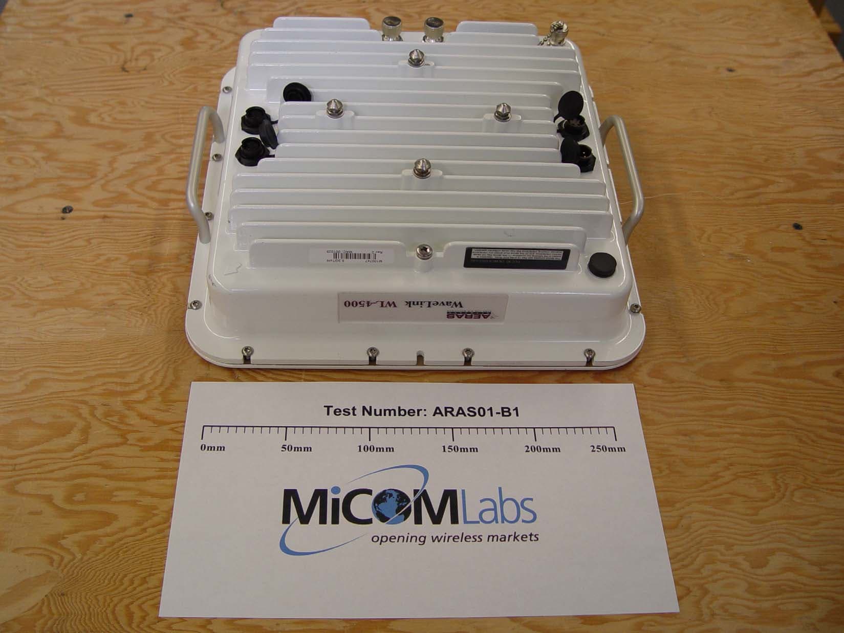
Click to zoom
Application Details
- Equipment Class
- NII - Unlicensed National Information Infrastructure TX
- Date of Grant
- Aug 04, 2004
- Application Purpose
- Original Equipment
- Date of Application
- Aug 04, 2004
- Equipment Note
- Line of Sight Digital Radio Transmission System
- Frequency Range
- 5250.00000000 - 5350.00000000
- Company
- Aeras Networks, Inc.
- Country
- United States
Documents & Files
Document Text
Text extracted from the exhibit documents filed with the FCC. Open a document above to read the original.
Users Manual
Aeras WaveLink User Manual Part Number MANL-5X-150-001 6/03 Version A ii This products described in this document are products of Aeras Networks or its licensers. No part of this document may be photocopied, reproduced, translated, transferred, disclosed or otherwise provided to third parties without the prior written consent of an officer of Aeras Networks. This document applies to the Aeras Network release of the WaveLink product line and to all subsequent versions and releases of the hardware or software unless otherwise indicated in a new version or an update package for this edition. Publications requests should be addressed to your local sales support office. Aeras Networks reserves the right to make changes to any products described herein at any time without notice. Aeras Network does not assume any responsibility or liability arising out of the application or use of any product described herein, except as expressly agreed to in writing by Aeras Networks nor does the purchase or use of a product from Aeras Networks convey a license under any patent rights, copyrights, trademark rights, or any other of the intellectual property rights of Aeras Networks or third parties. Use, duplication, or disclosure in this document is furnished under a license agreement or nondisclosure agreement. The software described in this document is furnished under a license agreement or nondisclosure agreement. The software may be used or copied only in accordance with the terms of the agreement. It is a violation of Aeras Networks proprietary rights to copy the software of any medium except as specifically allowed in the license or nondisclosure agreement. © 2003 Aeras Network. All Rights Reserved iii United States Federal Communications Commission Required Use Documentation This equipment complies with Part 15 of the FCC Rules. Operation is subject to the following two conditions: (1) this device may not cause harmful interference, and (2) this device must accept any interference received, including interference that may cause undesired operation. Changes or modifications not expressly approved by Aeras Networks in writing can void the user’s authority to operate this equipment. This device must be professionally installed. This device is to be exclusively used for fixed point-to-point operation with directional antennas. iv Aeras WaveLink User Manual, Version A (this page intentionally left blank) 5HJXODWRU\ ,QIRUPDWLR v Table of Contents Welcome! ............................................................................................................. ix Document Organization ........................................................................................ ix • Microwave Radiation Warnings ........................................................................... ix • Regulatory Information ......................................................................................... x • Related Documentation ...................................................................................... xi • Customer Support Services ................................................................................xii • Conventions Used in this Manual ......................................................................xiv Chapter 1 System Description . . . . . . . . . . . . . . . . . . . . . . . . . . . . . . . . . . . . . . . . . . . . . . . .1 1-1General......................................................................................................................1 1-1.1 Products .......................................................................................................... 1 1-1.2 Applications ..................................................................................................... 2 1-2System Overview ...................................................................................................... 2 1-3Features ....................................................................................................................5 1-4Aeras WaveLink Basic Structure ............................................................................... 6 1-4.1 Radio Links ..................................................................................................... 6 1-4.2 Data Stream .................................................................................................... 6 1-4.3 Aeras WaveLink Models ................................................................................. 6 1-4.4 Mounting and Antenna Alignment ................................................................... 8 1-4.5 Interface Connectors and Indicators ............................................................... 8 1-4.6 Cables ........................................................................................................... 10 1-4.7 Integral Antenna ............................................................................................ 11 1-4.8 External Antenna ........................................................................................... 12 1-4.9 Configuration, Operation, and Monitoring ..................................................... 14 1-4.10 SNMP .......................................................................................................... 14 1-4.11 Aeras WaveLink Network Management Architecture .................................. 15 1-4.12 NMS Connectivity ........................................................................................ 15 1-4.13 Web-Based GUI Access Security ............................................................... 16 1-4.14 GUI Functions ............................................................................................. 16 1-5Typical Applications................................................................................................. 18 1-5.1 Internet (ISP) ................................................................................................. 18 1-5.2 Private Network Wirel…
Text truncated - open the document above for the full version.
Users Manual
Preface Welcome! This manual is intended for the technical personnel who will install and operate the Aeras WaveLink. Such personnel are typically experienced and skilled technicians familiar with on site, physical installation and connection of equipment, including maintenance work. It is also intended for system administration personnel performing initial configuration and subsequent system reconfiguration, as well as current system maintenance activities. Document Organization This manual provides a detailed description of the Aeras WaveLink components, and operating, installation and management procedures. • Chapter 1 provides an overview and briefly describes typical applications. • Chapter 2 provides an installation steering guide with references to subsequent installation sections. • Chapter 3 describes how to plan the Aeras WaveLink network, radio links, and remote element and network management links, and individual Aeras WaveLink radios. • Chapter 4 provides detailed hardware installation and acceptance test procedures. • Chapter 5 describes final configuration procedures and the Web browser user interface. • Chapter 6 presents procedures for monitoring and performing trend analysis on the Aeras WaveLink. • Chapter 7 provides instructions for troubleshooting the Aeras WaveLink. • Appendixes provide detailed technical information for carrying out the installation and maintenance activities described in the other chapters of this manual. Microwave Radiation Warnings Radio Warning Under normal operating conditions, Aeras WaveLink radio equipment complies with the limits for human exposure to radio frequency (RF) fields adopted by the Federal Communications Commission (FCC). All Aeras Networks, Inc. microwave radio equipment is designed so that under normal working conditions, microwave radiation directly from the radio is negligible when compared with the permissible limit of continuous daily exposure recommended in the United States by ANSI/IEEE C95.1-1991 (R1997), Safety Levels with Respect to Human Exposure to Radio Frequency Electromagnetic Fields, 3 kHz to 300 GHz. Microwave signal levels that give rise to hazardous radiation levels can exist within transmitter power amplifiers, associated RF multiplexers, and antenna systems. Antenna Warning Designed for point-to-point operation, the Aeras WaveLink microwave radio system uses directional antennas to transmit and receive microwave signals. These directional antennas are usually circular or rectangular in shape, are generally located outdoors, and are usually mounted with the Aeras WaveLink on a tower or mast. The Aeras WaveLink is classified as a fixed installation product, and per FCC (Federal Communications Commission) policy guidelines regarding maximum permissible exposure (MPE), antennas used for this Aeras Networks radio must be installed to provide a separation distance of 2 m (79 in.) or more from all persons during normal operation to satisfy FCC RF exposure limits. As the Aeras WaveLink is typically mounted on a building or mast high enough to clear ground-level path obstructions, the general population will be further than 2 m (79 in.) from the radio antenna, and the FCC RF exposure limits will be met. Aeras Networks, Inc. fully supports the FCC’s adopted MPE limits, and recommends that personnel stay 2 m (79 in.) from the front of all directional microwave antennas. Should you have questions about Aeras WaveLink microwave signal radiation, please contact the Aeras Networks Customer Support. Regulatory Information FCC Compliance The Aeras WaveLink is FCC certified for use in the 5.3 GHz unlicensed band in the United States. The 5.3 GHz version of the Aeras WaveLink is certified under FCC part 15.407, U-NII regulations covering the frequency band of 5250-5350 MHz. 5.3 GHz (5.25-5.35 GHz) When deployed in an area regulated by the FCC, 5.3 GHz Aeras WaveLink radios are equipped with an integral antenna only, and operate under the FCC Part 15, subpart E, U-NII license-exempt regulations, which certify the radios for .0063 output watts . The 5.3 GHz Aeras WaveLink radio has been FCC certified in the following configuration: a c s Deleted: and 5.8 GHz Deleted: s Deleted: Deleted: –1.0 dBm average, or +7.4 dBm peak transmit powe r Deleted: s Deleted: have Deleted: <#>Aeras WaveLink, 5.3 GHz, inte gral antenna¶ Other Regulation Compliance Other countries have varying RF licensing and operating requirements, and it is imperative that operators and professional installers ensure that the Aeras WaveLink is configured and installed per regional regulations. For instance, ETSI I-ETS 300 440 describes the bands that the Aeras WaveLink is permitted to operate in, and limits transmissions to 25 milliwatts EIRP (Power Class 9). Related Documentation All Aeras Networks manuals are available in an online format on our protected Internet site. To order user documentation, please contact Aeras Networks, Inc. Sales department online at http://www.aerasnetworks.com. Updates to this manual will be posted on the Aeras Networks, Inc. Customer Support website at http://www.aerasnetworks.com/custsupport. Registered Aeras Networks customers can access the Aeras Networks online information and support service, available 24 hours a day, seven days a week. The Aeras Networks online service provides users with a wealth of up- to-date information, with documents being added or updated each month. Deleted: 5.8 GHz (5.725-5.825 GHz)¶ When deployed in an area regulated by the FCC, 5.8 GHz Aeras WaveLink radios operate under the FCC Part 15.247 band regulations, which certify the radios for +16 dBm average or +24.1 dBm peak transmit power for intentional radiators in a point-to-point configuration. The 5.8 GHz Aeras WaveLink radios are equipped with an integral or an external antenna. The 5.8 GHz Aeras WaveLink radios have been FCC certified in the following configurations:¶ <#>Aeras WaveLink, 5.8 GHz, integral antenna¶ <#>Aeras WaveLink, 5.8 GHz, 2 ft…
Text truncated - open the document above for the full version.
RF Exposure Info
3922 Valley Avenue, Suite B, Pleasanton, CA 94566, Tel.: 925.462.0304, Fax: 925.462.0306, www.micomlabs.com Calculations for Maximum Permissible Exposure Levels Wednesday, July 21, 2004 AERAS Networks ARAS01-B1 Aeras Networks WaveLink 4500 5.3GHz Microwave Fixed Link RF Radiation Exposure FCC, Part 15 Subpart C §15.247(f) Industry Canada RSS-210 §6.2.2(q1)(iv)(g) Given E = √(30 * P * G) / d and S = E 2 / 3770 where E = field strength in volts/meter P = power in watts G = numeric antenna gain d = distance in meters S = power density in milliwatts / square centimeter Combining and rearranging the terms to express the distance as a function of the variables, yields: d = √(30 * P * G) / (3770 * S) Rearrange to milliwatts and centimeters P(mw) = P(watts) / 1000 d(cm) = d(m) * 100 yields d = 100 * √(30 * (P / 1000) * G) / (3770 * S) d = 0.282 * √(P * G / S) where d = distance in centimetres P = Power in mW G = Numeric Antenna Gain S = Power Density in centimetres 2 Substituting the logarithmic form of power and gain using: P(mW) = 10 ^ (P(dBm)/10) and G(numeric) = 10 ^ (G(dBi) /10) Yields: d = 0.282 * 10 ^ ((P + G) / 20) /√ S where d = MPE distance in centimetres P = Power in dBm G = Antenna Gain in dBi S = Power Density Limit in mW / centimetres 2 (Limit S = 1mW / cm 2 from §1.310 Table 1) Maximum output power observed from power measurements – +7.9dBm Maximum antenna gain – 28.5dBi Power Density Limit (mW / cm 2 ) Maximum Measured Output Power (dBm) Antenna Gain (dBi) MPE Distance (cm) 1 7.9 28.5 18.6 MPE Distance 18.6cm
Test Report
Test of Aeras Networks WaveLink 4500 Microwave Fixed Link To FCC 47 CFR Part 15.407/IC RSS-210 Test Report Serial No.: ARAS01-B1 Rev E TEST REPORT FROM Test of Aeras Networks WaveLink 4500 5.3GHz Microwave Fixed Link To FCC 47 CFR Part 15.407/IC RSS-210 Test Report Serial No.: ARAS01-B1 Rev E This report supersedes ARAS01-B1 Rev D Remarks: Equipment complied with the specification[X] Equipment did not comply with the specification[ ] This Test Report is issued Under the Authority of: Gordon Hurst President & CEO Copy No: pdf Issue date: 28th July 2004 Manufacturer:Aeras Networks 18735 Madrone Parkway Morgan Hill, California 95037 U.S.A. This test report may be reproduced in full only 2106 Title: To: Serial #: Issue Date: Page: Test of Aeras Networks WaveLink 4500 5.3GHz Microwave Fixed Link FCC 47 CFR Part 15.407/IC RSS-210 ARAS01-B1 Rev E 28th July 2004 2 of 52 This page has been left intentionally blank Title: To: Serial #: Issue Date: Page: Test of Aeras Networks WaveLink 4500 5.3GHz Microwave Fixed Link FCC 47 CFR Part 15.407/IC RSS-210 ARAS01-B1 Rev E 28th July 2004 3 of 52 CONTENTS 1EXECUTIVE SUMMARY ..............................................................................................4 2TECHNICAL DETAILS..................................................................................................5 2.1Normative References .............................................................................................................6 2.2Test and Uncertainty Procedures.............................................................................................7 3TEST SUMMARY ............................................................................................................8 3.1List of Measurements ..............................................................................................................8 3.2Test Configurations .................................................................................................................9 4MEASUREMENTS, EXAMINATIONS AND DERIVED RESULTS ......................11 4.1General observations .............................................................................................................11 4.2Test Results ...........................................................................................................................12 4.2.1Device Characteristics ..................................................................................................12 4.2.1.126dB and 99% Emission Bandwidth and Power Limits .........................................................12 4.2.1.2Output Power .........................................................................................................................14 4.2.1.3Peak Power Spectral Density .................................................................................................16 4.2.1.4Antenna Gain - Power Reduction Calculations......................................................................18 4.2.1.5Peak Excursion Ratio .............................................................................................................19 4.2.1.6Automatic Discontinuation of Transmission ..........................................................................21 4.2.1.7Frequency Stability.................................................................................................................22 4.2.1.8RF Radiation Exposure ..........................................................................................................23 4.2.1.9AC Wireline Conducted Emissions (150KHz – 30MHz).........................................................25 4.2.1.10Radiated Emissions (30MHz – 1GHz)................................................................................27 4.2.1.11Spurious Emissions (1GHz - 40GHz).................................................................................30 5PHOTOGRAPHS ...........................................................................................................33 5.1Radiated Emissions (OATS) Test Set Up (30MHz-1GHz)...................................................33 5.2Spurious Emissions Test Set Up (1-40GHz) .........................................................................34 5.3General Measurement Test Set Up........................................................................................35 5.4Equipment Internals ..............................................................................................................36 6TEST EQUIPMENT DETAILS ....................................................................................37 7GRAPHICAL RESULTS ...............................................................................................38 Band-Edge .........................................................................................................................................38 26dB Bandwidth Plots (ARAS01-B1/01-02) ....................................................................................39 99% Bandwidth Plots (ARAS01-B1/03-04) .....................................................................................41 Peak Excursion Ratio (ARAS01-B1/05-06)......................................................................................43 AC Wireline Emissions (ARAS01-B1/07-08) ..................................................................................45 Pre-scan Emission Plots 30-1GHz (ARAS01-B1/09-10)..................................................................47 Spurious Emissions Plots 1-40GHz Conducted (ARAS01-B1/11-13)..............................................49 Band-Edge Plots Conducted 30MHz – 15GHz, High-Band (ARAS01-B1/14) ................................51 Band-Edge Plots Conducted 30MHz – 15GHz, Low-Band (ARAS01-B1/15).................................52 Title: To: Serial #: Issue Date: Page: Test of Aeras Networks WaveLink 4500 5.3GHz Microwave Fixed Link FCC 47 CFR Part 15.407/IC RSS-210 ARAS01-B1 Rev E 28th July 2004 4 …
Text truncated - open the document above for the full version.
Test Report
5.15 GHz 5.35 GHz Trd PRETRD 1M A Unit dB Ì V/m ResBW 1 MHzMeas T 100 msDet MA Att 20 dB INPUT 1 30 40 50 60 70 80 90 100 110 20 120 1 Marker 1 [T1] 44.53 dB Ì V/m 5.35000000 GHz 1 [T1] 44.53 dB Ì V/m 5.35000000 GHz Date: 31.JUL.2004 16:34:11 5.15 GHz 5.35 GHz Trd PRETRD 1M A Unit dB Ì V/m ResBW 1 MHzMeas T 100 msDet MA Att 20 dB INPUT 1 30 40 50 60 70 80 90 100 110 20 120 1 Marker 1 [T1] 44.00 dB Ì V/m 5.15000000 GHz 1 [T1] 44.00 dB Ì V/m 5.15000000 GHz Date: 31.JUL.2004 16:08:29
Test Report
Justification for professional installation Marketing and Application The WaveLink 4500 system has been designed and is intended for use as an alternative to traditional wireline methods of providing DS3 and High-Speed Ethernet connectivity. As such the end user of this system will be enterprise businesses, local telephone companies or utility companies. The actual customer for, and operator of WaveLink 4500 networks will be Service Providers such as ISP’s, Competitive Access Providers (CAP’s) or the local telco’s themselves. This places the use of the system decidedly in the industrial/commercial application arena. Furthermore, many of the aforementioned target customers are already involved in wireless communications technologies and have on staff professional RF installation crews. For those Service Providers who do not to date have in-house talent for the RF installation of the WaveLink 4500 system, e.g. ISP’s, they will be directed to a network of third party providers (largely from the cellular/PCS arena) who specialize in microwave equipment installations. Examples of some of these support shops are Valcom in the mid-west, and Netcom International based in Atlanta. Technical Requirements There are several steps involved in the setup and installation of the system that require tool's and skills not found in the average technically inclined person’s skill set. Some of these are: • Physical Installation - these units are designed and intended for outdoor installation. The units will be located on towers on tall buildings typical for microwave equipment sites. Access to these locations is typically restricted to those with authorization, which restricts access from the average lay person. Furthermore, when installing the systems weather sealing of connectors is required, an additional somewhat specialized task. • Antenna Alignment – in order to align the antennas of the system, it is necessary for the installer to adjust the antenna based upon an RSSI (Received Signal Strength Indicator) voltage measured at a test point on the radio unit • Power Requirements – The WaveLink 4500 radio requires a DC voltage from 21 to 60 VDC to operate. As this is outside the normal household appliance voltage, the user must seek AC to DC or Battery systems which unique to systems requiring professional expertise or installation.
Test Setup Photos
ARAS01-B1 WaveLink 4500 TEST SET UP Conducted Tests TEST SET UP 30M-1GHz Spurious Emissions TEST SET UP 1-40GHz Spurious Emissions
Contact Information
Applicant
Nicholas Dow Wolfgang Luesing(Executive Director, T1/E1 Products)
Technical Contact
Areas Networks, Inc.Nick Luesing
[email protected]408-182-9991
18735 Madrone Parkway · Morgan Hill, California · United States
Non-Technical Contact
Areas Networks, Inc.Nick Luesing
[email protected]408-182-9991
Test Firm
Micom LabsGordon Hurst
Technical Specifications
| # | Rule Parts | Frequency Range | Power Output |
|---|---|---|---|
| 1 | 15E | 5.25 GHz - 5.35 GHz | 5.00 mW |