RWWLS1700V17" LCD Monitor
Orion Technology Inc.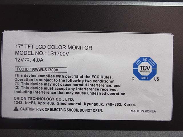
Click to zoom
Application Details
- Equipment Class
- JBP - Part 15 Class B Computing Device Peripheral
- Date of Grant
- Jun 14, 2005
- Application Purpose
- Original Equipment
- Date of Application
- Jun 14, 2005
- Equipment Note
- 17" LCD Monitor
- Company
- Orion Technology Inc.
- Country
- South Korea
Documents & Files
Document Text
Text extracted from the exhibit documents filed with the FCC. Open a document above to read the original.
Users Manual
LS1700V TFT-LCD MONITOR INSTRUCTION MANUAL Please read this manual thoroughly before use, and keep it handy for future reference. SAFETY INSTRUCTION...............................................................................2 - 3 CAUTIONS ....................................................................................................4 FCC RF INTERFERENCE STATEMENT .............................................................5 CONNECTING WITH EXTERNAL EQUIPMENT................................................... 6 REMOTE FUNCTIONS ................................................................................... 7 CONTROLS AND FUNCTIONS....................................................................8 - 14 MOUNTING GUIDE ...................................................................................... 15 D-SUB CONNECTOR PIN ASSIGNMENTS .......................................................16 POWER MANAGEMENT................................................................................17 SPECIFICATIONS.................................................................................. ......18 TROUBLESHOOTING GUIDE. .......................................................................19 . 1....................................................................................... INSTRUCTION MANUAL 1. Read all of these instructions. 2. Save these instructions for later use. 3. Follow all warnings and instructions marked on the product. 4. Unplug this product from the wall outlet before cleaning. Do not use liquid cleaners or aerosol cleaners. Use a damp cloth for cleaning. 5. Do not use this product near water. 6. Do not place this product on an unstable cart, stand or table. The product may fall, causing serious damage to the product. 7. Slots and openings in the cabinet and the back are provided for ventilation: to ensure reliable operation of the product, these openings must not be blocked by placing the product on a bed, sofa, rug or other similar surface. This product should never be placed near or over a heat register. This product should not be placed in a built-in installation unless proper ventilation is provided. 8. This product should be operated from the type of power source indicated on the marking label. If you are not sure of the type of power available, consult your dealer or local power company. 9. This product is equipped with a 3 wire grounding type plug having a third(grounding) pin. This is a safety feature. If you are unable to insert the plug into the outlet, contact your electrician to replace your obsolete outlet. Do not defeat the purpose of the grounding-type plug. 10. Do not allow anything to rest on the power cord. Do not locate this product where persons will walk on the cord. 11. If an extension cord is used with this product, make sure that the total of the ampere ratings on the products plugged into the extension cord do not exceed the extension cord ampere rating. Also, make sure that the total of all products plugged into the wall outlet does not exceed 10 amperes. 12. Never push objects of any kind into this product through cabinet slots as they may touch dangerous voltage points or short out parts that could result in a risk of fire or electric shock. Never spill any kind of liquid on the product. 13. Do not attempt to service this product yourself, as opening or removing covers may expose you to dangerous voltage points or other risks. INSTRUCTION MANUAL .......................................................................................... 2 Refer all servicing to service personnel. 14. Unplug this product from the wall outlet and refer servicing to qualified service personnel under the following conditions. A. When the power cord or plug is damaged or frayed. B. If liquid has been spilled into the product. C. If the product has been exposed to rain or water. D. If the Product does not operate normally when the operating instructions are followed. Adjust only those controls that are covered by the operating instructions since improper adjustment of other controls may result in damage and will often require extensive work by a qualified technician to restore normal operation. E. If the product has been dropped or the cabinet has been damaged. F. If the product exhibits a distinct change in performance, indicating a need for service. CAUTIONk The power supply cord is used as the main disconnect device, ensure that the socket-outlet is located/installed near the equipment and is easily accessible. ATTENTIONN Le cordon d`alimentation est utillsé comme interrupteur général. La prise de courant doit être située ou installée à proximité du matériel et être facile d`accès 3 .......................................................................................... INSTRUCTION ▶ NEVER REMOVE THE BACK COVER Removal of the back cover should be carried out only by qualified personnel. ▶ DO NOT USE IN HOSTILE ENVIRONMENTS To prevent shock or fire hazard, do not expose the unit to rain or moisture. This unit is designed to be used in the office or home. Do not subject the unit to vibrations, dust of corrosive gases. ▶ KEEP IN A WELL VENTILATED PLACE Ventilation holes are provided on the cabinet to prevent the temperature from rising. Do not cover the unit or place anything on the top of unit. ▶ AVOID HEAT Avoid placing the unit in direct sunshine or near a heating appliance. ▶ TO ELIMINATE EYE FATIGUE Do not use the unit against a bright back ground and where sunlight or other light sources will shine directly on the monitor. ▶ BE CAREFUL OF HEAVY OBJECT Neither the monitor itself nor any other heavy object should rest on the power cord. Damage to a power cord can cause fire or electrical shock. INSTRUCTION MANUAL ....................................................................................... 4 NOTE This equipment has been tested and found to comply with the limits for a Class B digital device, pursuant to Part 15 of the FCC Rules. These lim…
Text truncated - open the document above for the full version.
Block Diagram
X-TAL 27MHz SCALER L V D S P A N E L AUDIO PROCCESSOR AUDIO AMP INVERTER RGB 8 H.V CLK DE RGB OSD RGB H.V, FB L R ON/OFF X-TAL 27MHz Composite Video SVHS PC Stereo out Analog RGB PC stereo AV Audio L,R 8 I2C BUS X-TAL 12 MHz BLOCK DIAGRAM FOR LS1700V MUX Adaptor 3.3V 5V 8V 12V 12V H:30KHz ~80KHz V:50Hz~ 75Hz
ID Label/Location Info
ID Label Sample Location Information
Test Report
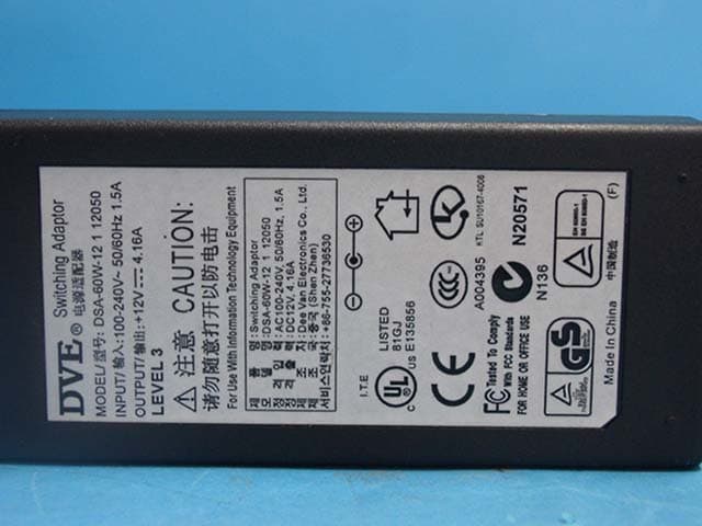
IST Co., Ltd EMC LABORATORY TEST REPORT NO. : 05-IST-0207 1 of 16 Certification of Compliance CFR 47 Part 15 Subpart B Test Report File No. : 05-IST-0207 Date of Issue : June 14, 2005 Model : LS1700V Kind of Product : LCD Monitor Applicant : Orion Technology Co., Ltd. Address : 1242, In-Ri, Apo-Eup, Gimcheon-Si, Kyungbuk, 740-862, Korea Manufacturer : Orion Technology Co., Ltd. Address : 1242, In-Ri, Apo-Eup, Gimcheon-Si, Kyungbuk, 740-862, Korea Test Result ■ Positive □ Negative Reviewed By Approved By Comment(s) - Investigations requested : Measurement to the relevant clauses of FCC rules and regulations Part 15 Subpart B – Unintentional Radiators, Class B. - The test report with appendix consists of 16 pages. - The test result only responds to the tested sample. - It is not allowed to copy this report even partly without the allowance of IST EMC Laboratory. - This equipment as for has been shown to be capable of continued compliance with the applicable technical standards as indicated in the measurement report and was tested in accordance with the measurement procedures specified in ANSI C63.4 2003. S. J. Cho / EMC Group Manager Joon H. Lee / Chief IST Co., Ltd EMC LABORATORY TEST REPORT NO. : 05-IST-0207 2 of 16 TABLE OF CONTENTS Table of contents 2 Information of test laboratory, Environmental conditions, Power used, Product information 3 Descriptions of test Conducted Emission 4 Radiated Emission 5 Equipment Under Test 6 Summary 7 ■ Test Conditions and Data - Emissions ◆ Conducted Emissions 0.15MHz - 30MHz Applicable Test Conditions / Data and Plots 8-10 ◆ Radiated Emissions 30MHz - 1GHz Applicable Test Conditions / Data and Plots 11-12 Appendix A. The Photos of Test Setup 13-14 B. The Photos of Equipment Under Test 15-16 Note : IST Co., Ltd EMC LABORATORY TEST REPORT NO. : 05-IST-0207 3 of 16 INFORMATIONS OF TEST LABORATORY EMC LABORATORY of IST Co., Ltd. (FCC Filing Lab.) San 21-8, Goan-Ri, Baekam-Myun, Yongin-City Kyonggi-Do, 449-860, Korea TEL : +82 31 333 4093 FAX : +82 31 333 4094 ENVIRONMENTAL CONDITIONS Temperature 21.3 °C Humidity 51 % Atmospheric pressure 1012 mbar POWER SUPPLY SYSTEM USED Power supply system AC 120Vac, 60Hz (Refer to the product information) PRODUCT INFORMATION LCD Type : Panel Model – LTM170E4-L21 (SAMSUNG LCD) 17-inch diagonal AM-TFT (Active Matrix) Pixel pitch – 0.264(H) x 0.264(V) mm Contrast ratio – 500:1 (Typical) Brightness – 300cd/m 2 (Typical) Response Time: 13msec(Typical) Resolution : 1280 x 1024, 75Hz (max.) Synchronization : Horizontal – 30~75 KHz, Vertical – 50~75 KHz Input Signal : Sync – separate TTL Level Video – Analog 0.7 Vp-p / 75 ohm S-Video, AV (Composite, Sound L/R) PC Stereo Sound Power Source : DSA-60W-12 1 12050(DVE, Made in China) In-100~240Vac, 50/60Hz 1.5A Out-DC12V, 4.16A Dimensions(W x H x D) : 18.5 x 16.9 x 7.5 Inch Weight-net / gross : 6.2 kg / 7.8 kg - EMC suppression device is not used during the test . - Please refer to user’s manual. IST Co., Ltd EMC LABORATORY TEST REPORT NO. : 05-IST-0207 4 of 16 < Concept Drawing > 215 >150 >40 80 Receiver DUT LISN 80 ≥ 80 80 40 ≥ 80 Measuring apparatus Mains Filter Mains Rear side Equipment under test Coaxial cable Artificial mains networ k Screened room Non-metallic support 80 DESCRIPTIONS OF TEST Conducted Emissions: The measurement were performed over the frequency range of 0.15MHz to 30MHz using a 50 Ω /50uH LISN as the input transducer to a Spectrum Analyzer or a Field Intensity Meter. The measurements were made with the detector set for "Peak" amplitude within a bandwidth of 10KHz or for "quasi-peak" & “Average” within a bandwidth of 9KHz. - Procedure of Test The line-conducted facility is located inside a shielded room No.1. A 1m X 1.5m wooden table 80cm height is placed 40cm away from the vertical wall and 1.5m away from the other wall of the shielded room. The R/S ESH3-Z5 and EMCO 3825/2 LISN are bonded to bottom of the shielded room. The EUT is located on the wooden table with distance more than 80cm from the LISN and powered from the EMCO LISN .The peripheral equipment is powered from the other LISN. Power to the LISNs are filtered by a noise cut power line filters. All electrical cables are shielded by braided tinned steel tubing with inner φ 1.2cm. If the EUT is a DC-powered device, power will be derived from the source power supply it normally will be powered from and this supply lines will be connected to the EMCO LISN. All interconnecting cables more than 1m were shortened by non-inductive bundling to a 1m length. Sufficient time for the EUT, support equipment, and test equipment was allowed in order for them to warm up to their normal operating conditions. The RF output of the LISN was connected to the R/S receiver to determine the frequency producing the maximum emission from the EUT. The frequency producing the maximum level was reexamined using Quasi-Peak mode by manual measurement, after scanned by automatic Peak mode for frequency range from 0.15 to 30MHz. The bandwidth of the receiver was set to 10kHz. The EUT, peripheral equipment, and interconnecting cables were arranged and manipulated to maximize each EME emission. < Side View > IST Co., Ltd EMC LABORATORY TEST REPORT NO. : 05-IST-0207 5 of 16 DESCRIPTION OF TEST Radiated Emissions: The measurement was performed over the frequency range of 30MHz to 1GHz using antenna as the input transducer to a Spectrum analyzer or a Field Intensity Meter. The measurement was made with the detector set for "quasi-peak" within a bandwidth of 120KHz. - Procedure of Test Preliminary measurements were made at 3 meter using bi-conical and log-periodic antennas, and spectrum analyzer to determine the frequency producing the max. emission in anechoic chamber. Appropriate precaution was taken to ensure that all emission from the EUT were maximized and investigated. The system configuration, mode of operation, turn-table azimuth and height with respect to the antenna were noted for each frequency found. The spectrum was scanned …
Text truncated - open the document above for the full version.
Contact Information
Applicant
Ho-Gu Hur(Manager of R&D)
Test Firm
IST Co., LtdBong Kyoon Bae
Technical Specifications
| # | Rule Parts | Frequency Range | Power Output |
|---|---|---|---|
| 1 | 15B | - | - |
Other Applications from Orion Technology Inc.
RWWLS1900V
Jun 14, 200519" LCD Monitor
Equipment Class
JBP - Part 15 Class B Computing Device Peripheral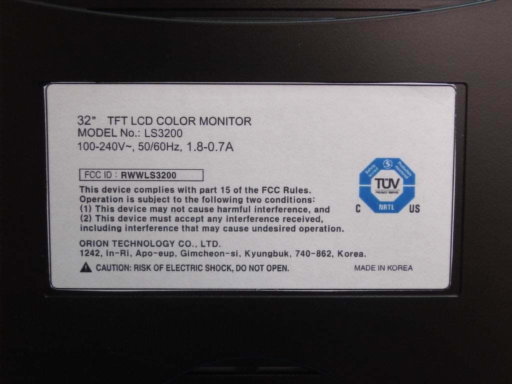
RWWLS3200
Apr 13, 200532 Inch TFT-LCD Monitor
Equipment Class
JBP - Part 15 Class B Computing Device Peripheral
RWWLS1500
Apr 13, 200515 Inch TFT-LCD Monitor
Equipment Class
JBP - Part 15 Class B Computing Device Peripheral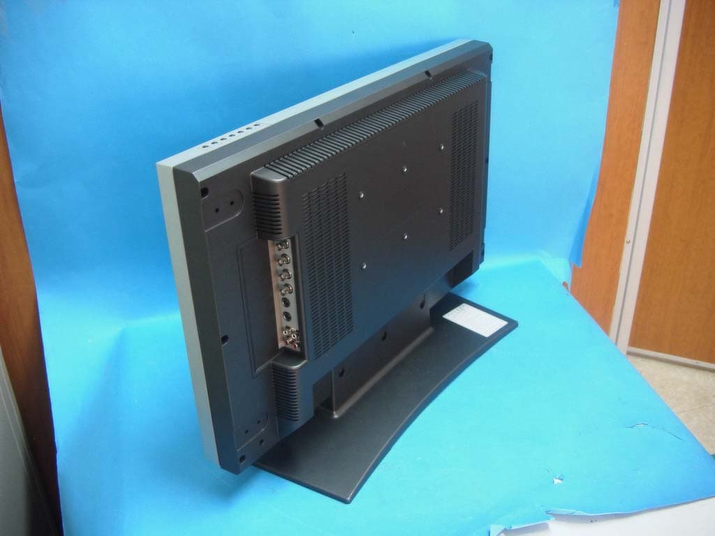
RWWLS2600
Dec 12, 2004LCD Monitor
Equipment Class
JBP - Part 15 Class B Computing Device Peripheral
RWW200RTC
Aug 25, 200420" LCD Monitor
Equipment Class
JBP - Part 15 Class B Computing Device Peripheral