RXJ-MRL800Radar Level Transmitter
Mobrey Limited
Click to zoom
Application Details
- Equipment Class
- DXT - Part 15 Low Power Transceiver, Rx Verified
- Date of Grant
- Nov 17, 2004
- Application Purpose
- Original Equipment
- Date of Application
- Nov 17, 2004
- Equipment Note
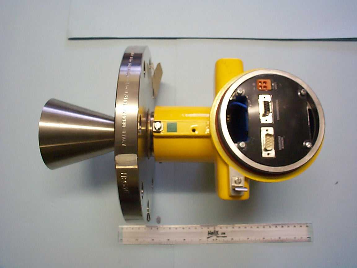
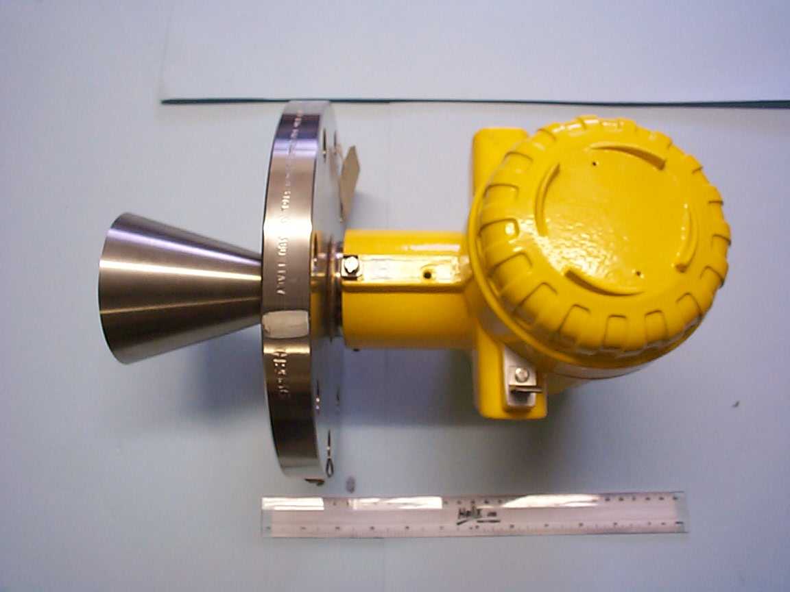
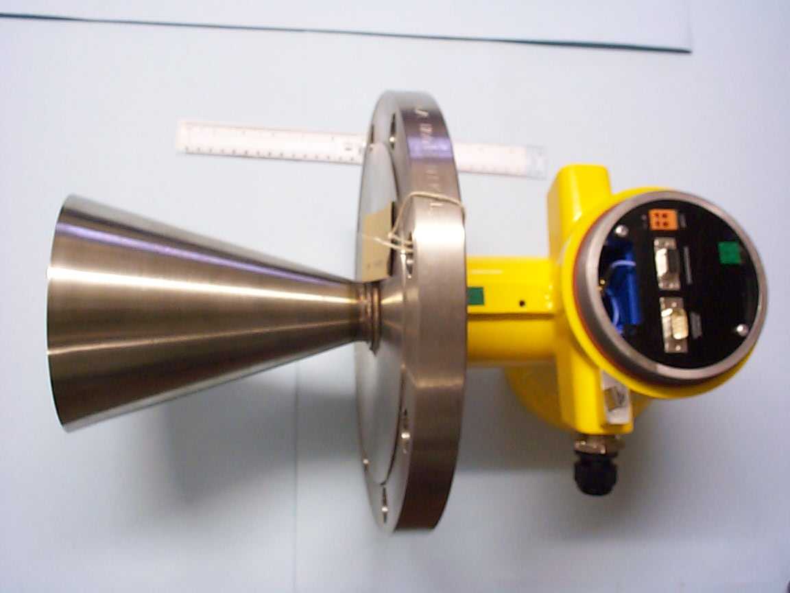
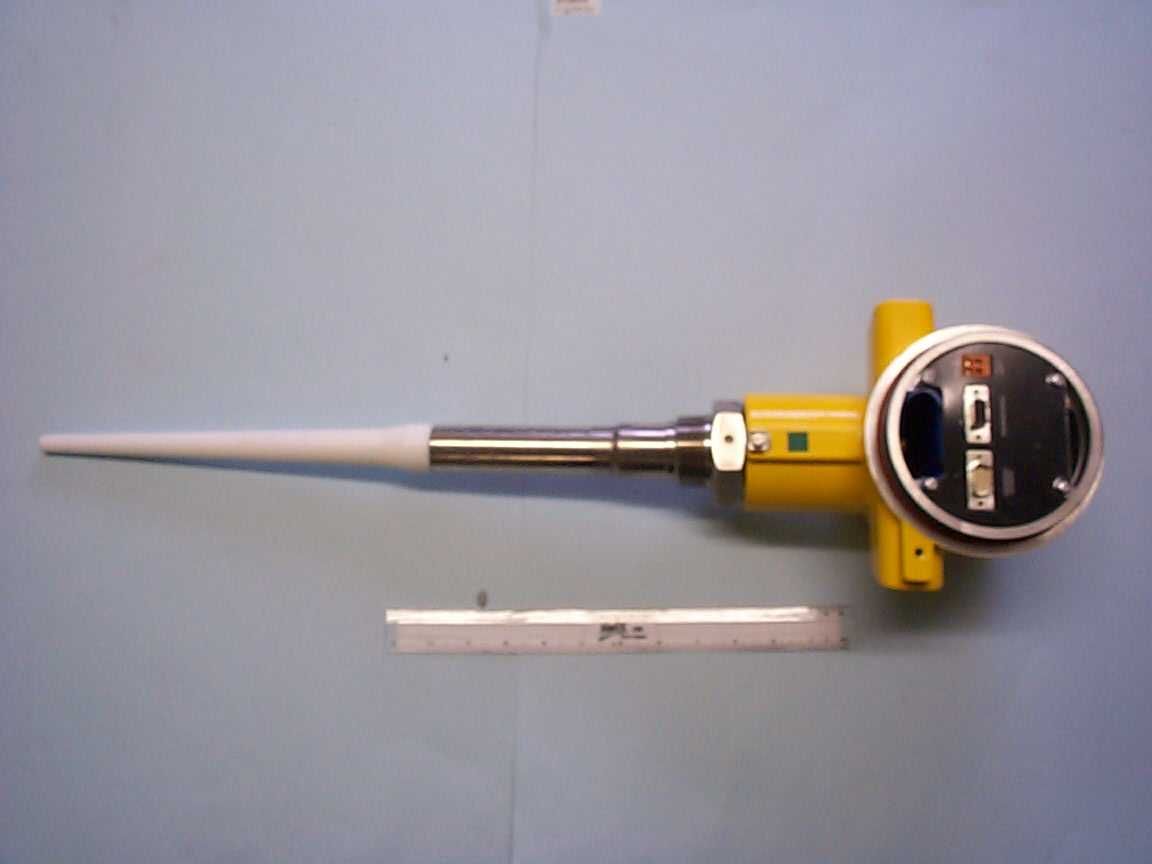
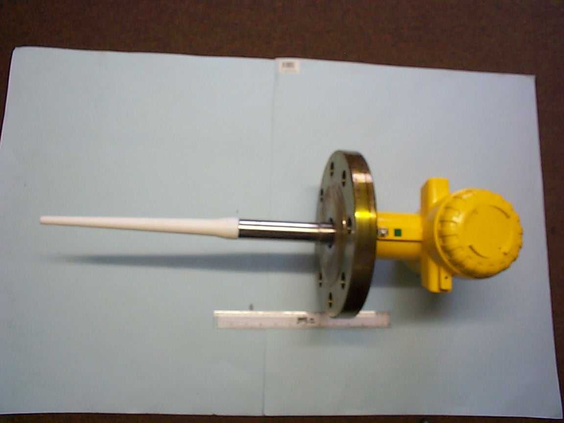
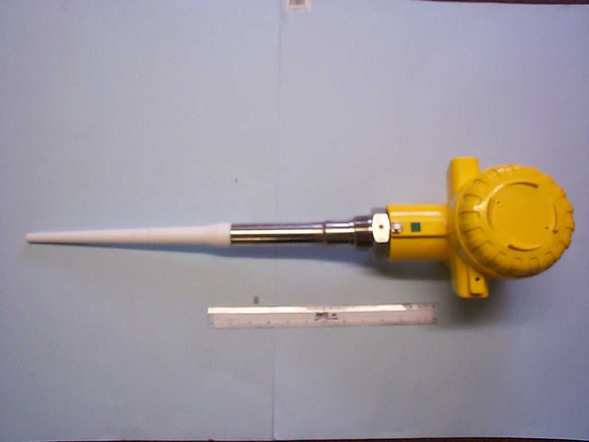
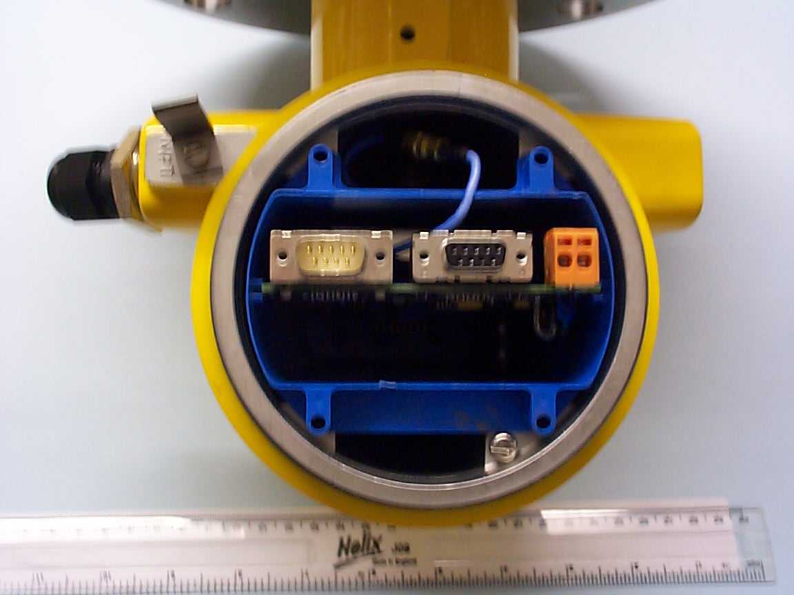
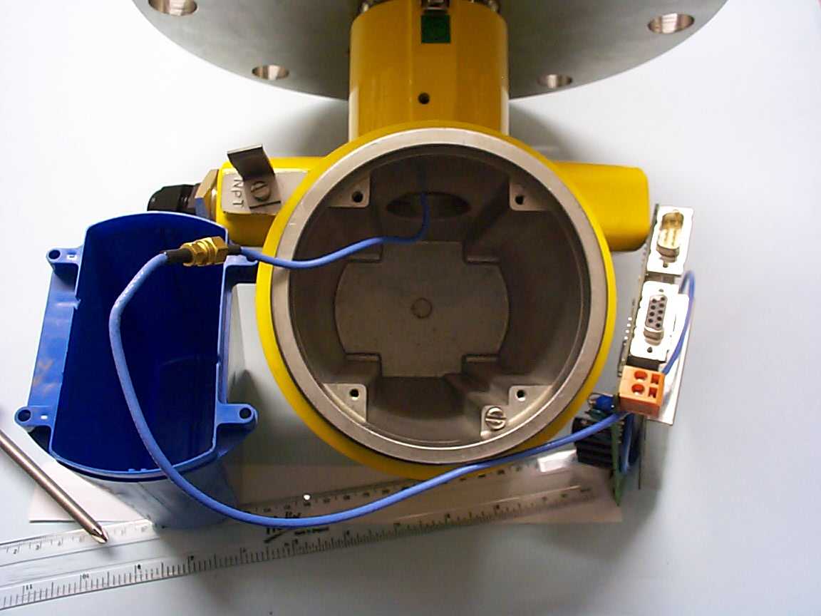
- Radar Level Transmitter
- Frequency Range
- 5500.00000000 - 6450.00000000
- Company
- Mobrey Limited
- Country
- United Kingdom
Documents & Files

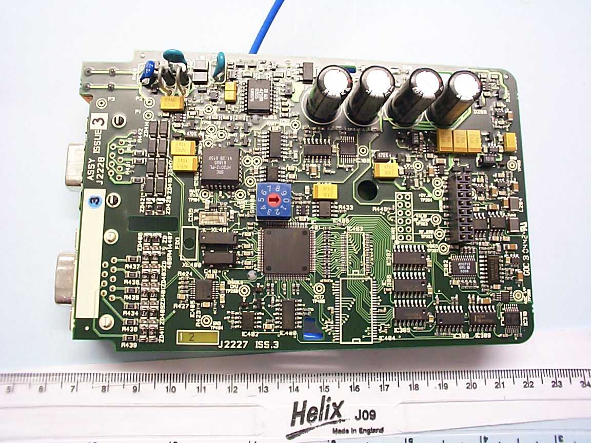
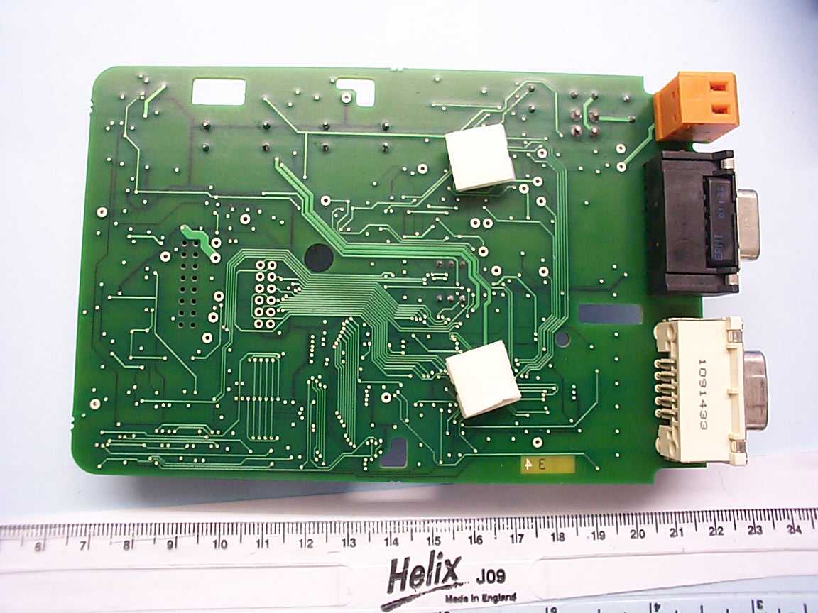
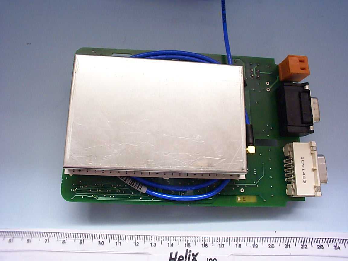
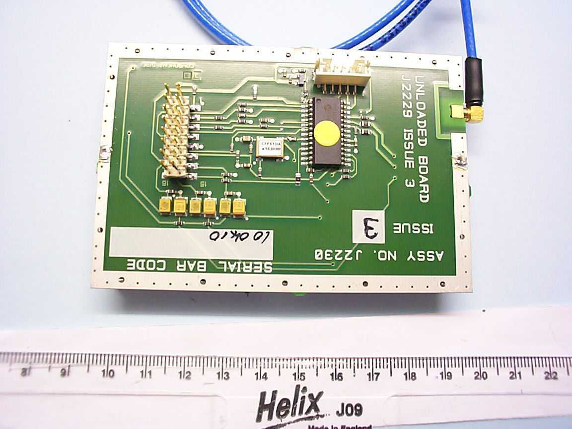
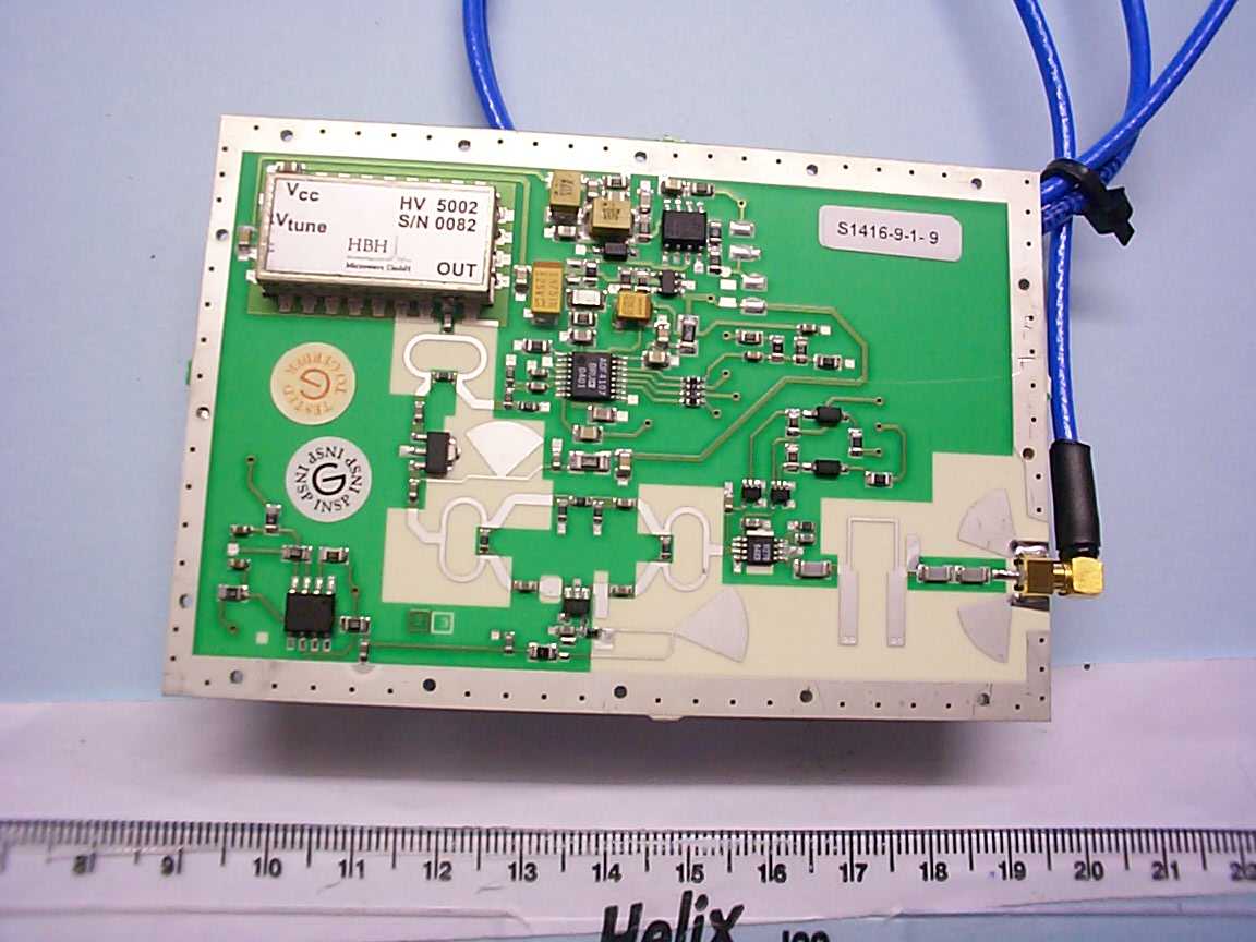
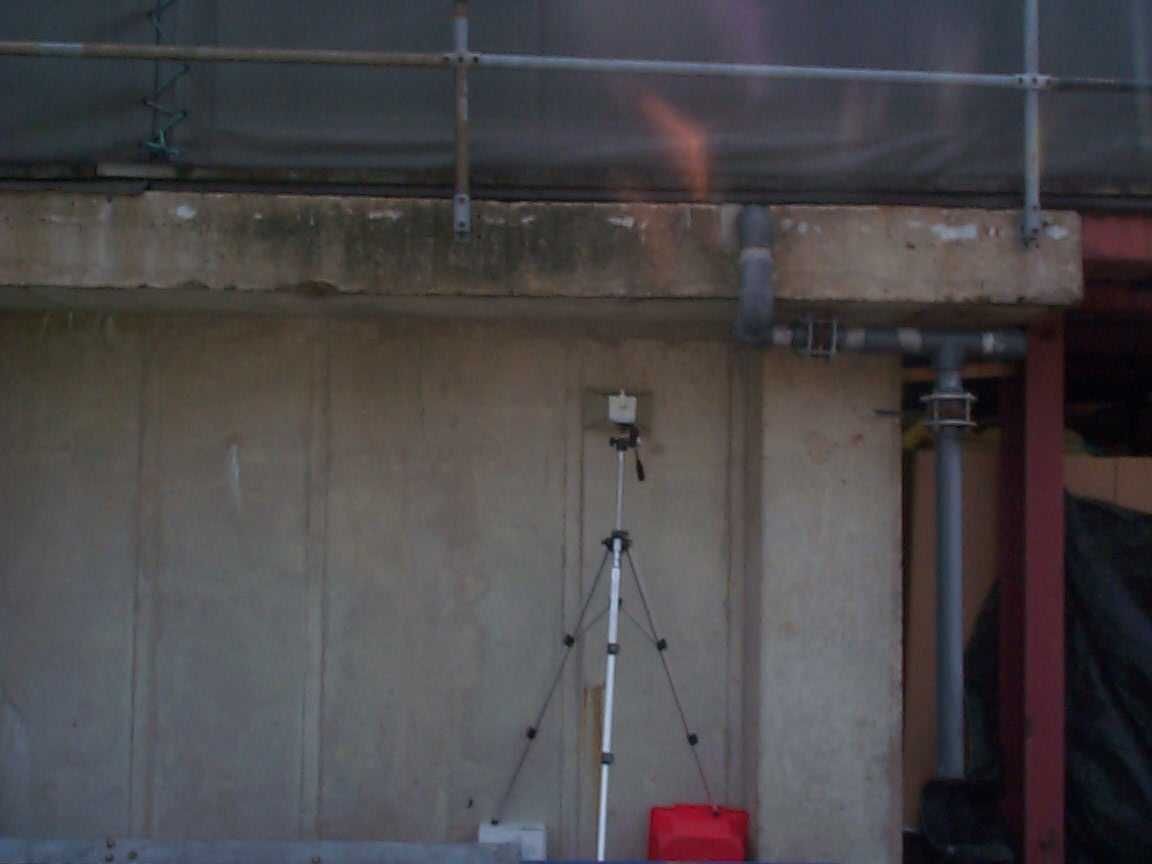
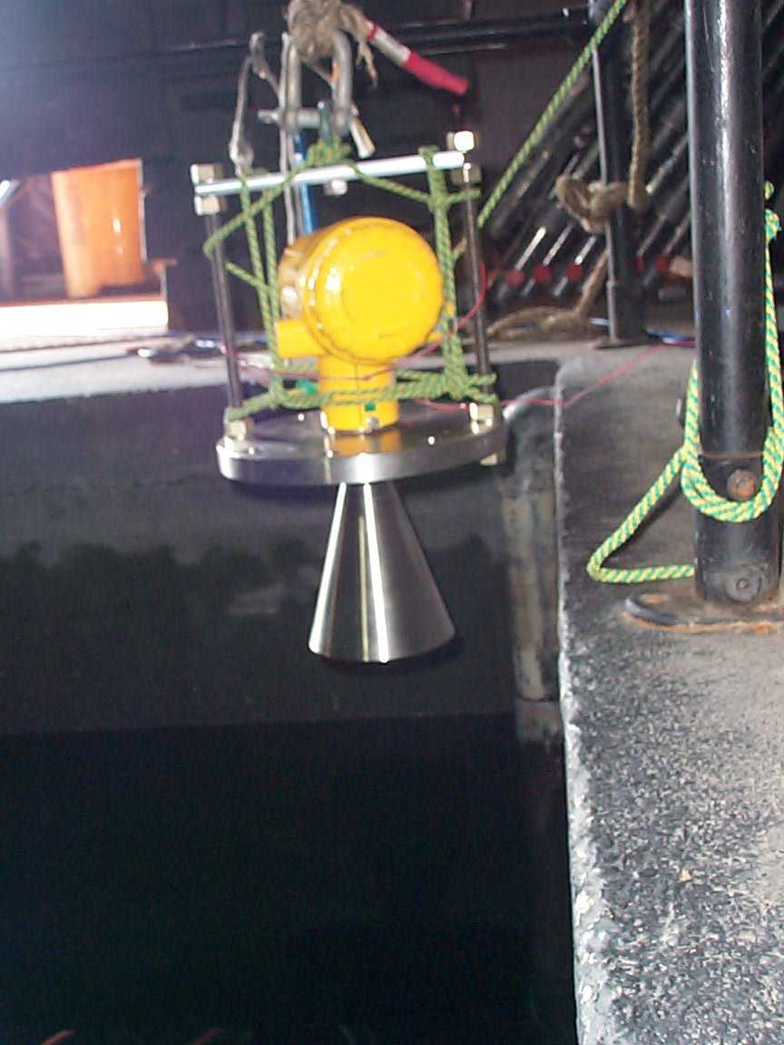
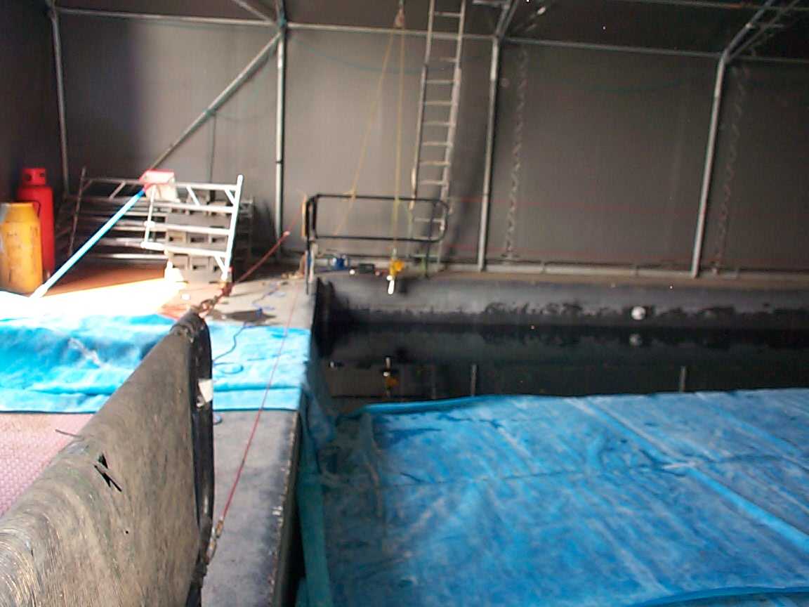
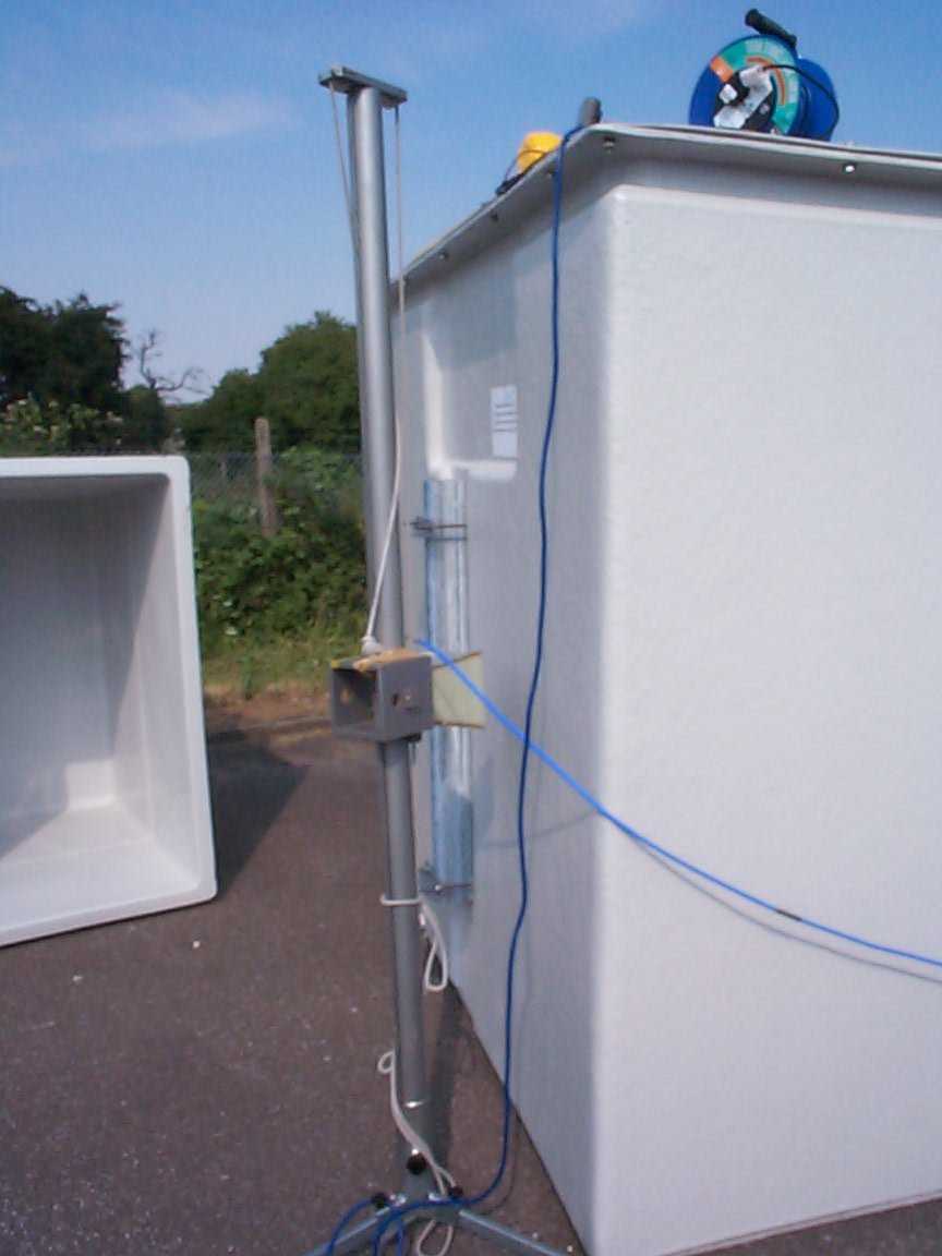
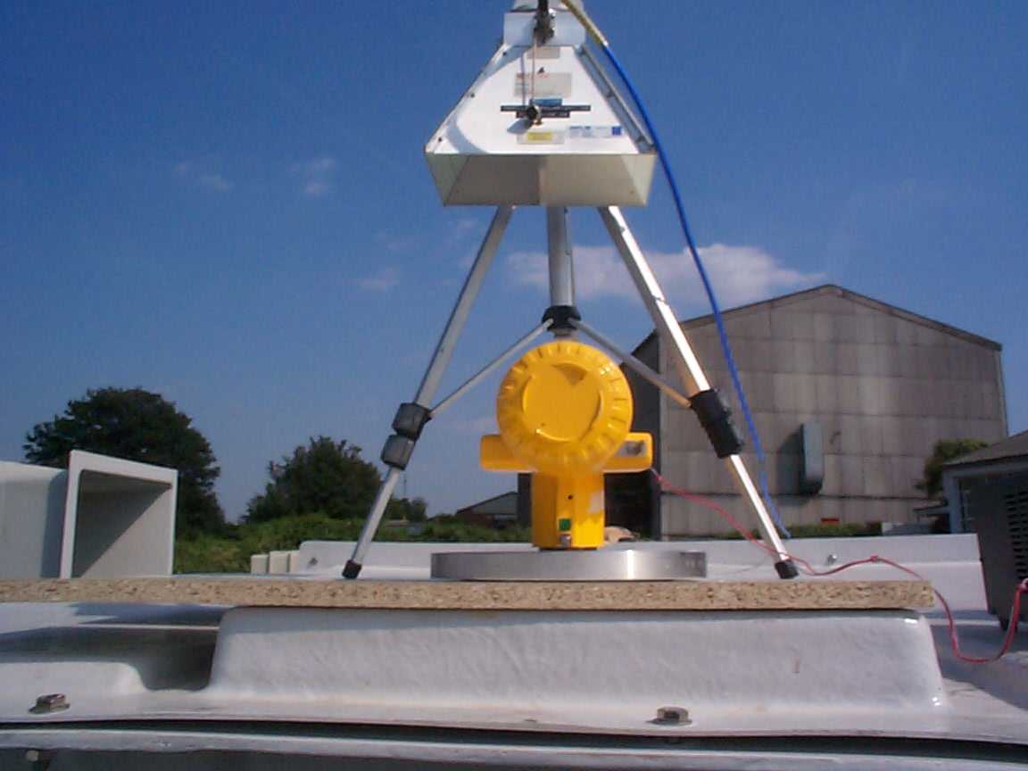
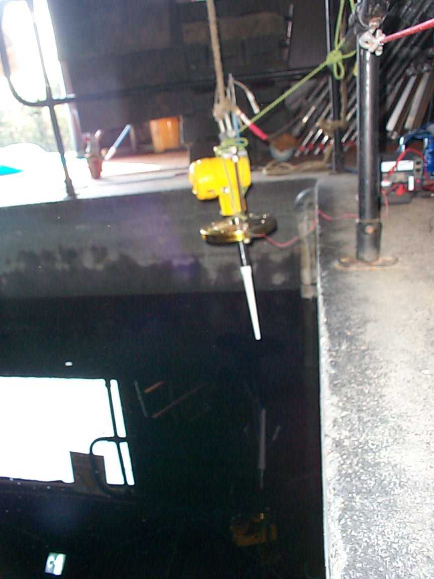
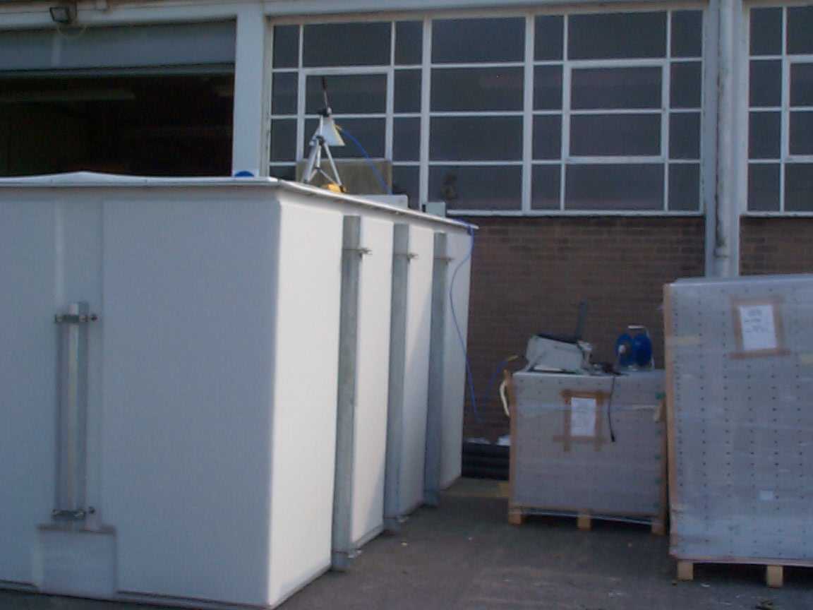
Document Text
Text extracted from the exhibit documents filed with the FCC. Open a document above to read the original.
Users Manual
Page 1 IP2028/IM Installation & Maintenance Manual IP2028/IM Radar Level Transmitter Radar-Based Continuous Level Measurement process measurement solutions ! 891 518 Page 2 IP2028/IM Disclaimer Solartron Mobrey has made every effort to ensure the accuracy and completeness of this manual. However, we cannot be responsible for errors, omissions or any loss of data as a result of errors or omissions. Solartron Mobrey reserves the right to make changes to the manual or improvements to the product at any time without notice. The material in this manual is proprietary and cannot be reproduced in any form without express written consent from Solartron Mobrey. Trademarks All registered trademarks are the property of their respective companies. Associated Publications IP2028/SISafety Instructions (ATEX) IP2028/QSQuick Start Operating Manual IP2028/OMTechnical Handbook IP293Sales Brochure L2007Radio Licence Application Pack (United Kingdom) Page 3 IP2028/IM Page 1.0Introduction ........................................................7 1.1Description .........................................................7 1.2How the Radar Level Transmitter Works ......................10 1.3How to use this manual ..........................................10 1.4Technical Services .................................................11 2.0Installation Procedure .............................................12 2.1Radio Licensing Approval .........................................12 2.2General installation requirements ..............................14 2.3Hazardous area installation ......................................14 2.4Selecting a Location ..............................................15 2.5Mounting the Radar Level Transmitter ........................16 3.0Wiring Procedure ..................................................20 3.1Wiring .................................................................20 3.2Programming & Commissioning ................................21 4.0Maintenance ........................................................25 5.0Spare Parts ..........................................................25 Appendices Appendix A : Rod Antenna : Threaded mounting .................26 Appendix B : Rod Antenna : Flange mounting ....................28 Appendix C : 4” Horn Antenna .......................................30 Appendix D : 6” Horn Antenna .......................................32 Table of Contents Page 4 IP2028/IM Safety Precautions The following safety precautions should be observed before using this product or working on the attached cables. This Radar Level Transmitter is intended for use by qualified personnel who recognize shock hazards and are familiar with the safety precautions required to avoid possible injury. Read the operating information carefully before using the product. The types of product users are: Responsible body: This is the individual or group responsible for the use and maintenance of equipment, and for ensuring that operators are adequately trained. Operators use the product for its intended function. They do not require access to the electrical connections within the instrument, and would normally only programme the instrument as required. Maintenance personnel perform routine procedures on the product to keep it operating, for example, checking the line voltage or checking electrical connections, replacing fuses etc. Service personnel are trained to work on live circuits, and perform safe installations and repairs of products. Only properly trained service personnel may perform installation and service procedures. Users of this product must be protected from electric shock at all times. Product users must be trained to protect themselves from the risk of electric shock. Before operating the instrument, make sure the supply is connected to a properly grounded power supply. Periodically inspect the connecting cables for possible wear, cracks, or breaks. Page 5 IP2028/IM To clean the instrument, use a damp cloth or mild, water based cleaner. Clean the exterior of the instrument only. Do not allow liquids to enter the instrument. WARNING - If this equipment is used in a manner not specified by Solartron Mobrey, the protection provided may be impaired. A protective earth should be used for all applications. The installation of the Radar Level Transmitter and its associated power cables must be such that tank overflow, local flooding or pump failure do not cause these to be submerged or subject to flows of water. Explanation of symbols: The IEC Protective Earth Symbol is : CHECK THAT THE POWER SUPPLY IS SUITABLE BEFORE SWITCHING POWER ON. Certification plate States hazardous area certification data Rod antenna model Page 6 IP2028/IM Approvals The Radar Level Transmitter is certified for use in hazardous locations as follows : ATEX • • FM • • • CSA • • • Note : Refer to the tag on your gauge for the latest hazardous location approval information. Detail available once certification process is complete Detail available once certification process is complete Detail available once certification process is complete The Radar Level Transmitter complies with Part 15 of the FCC Rules. Operation is subject to the following conditions: 1. This device may not cause harmful interference 2. This device must accept any interference received, including interference that may cause undesired operation 3. Any changes or modification made to this device, not expressly approved by the party responsible for compliance, could void the users authority to operate the equipment. Page 7 IP2028/IM 1.0Introduction The Radar Level Transmitter uses an FMCW microwave signal to measure the level of the process material. The Radar Level Transmitter provides superior performance to pulsed measurement systems, particularly in hostile environments, because the continuous microwave signal is unaffected by mist, surface agitation, temperature changes, or pressure changes. The standard menu-driven user interface, with buil…
Text truncated - open the document above for the full version.
Test Report
TRL C OMPLIANCE S ERVICES L TD EMC D IVISION M OSS V IEW N IPE L ANE U P H OLLAND W EST L ANCASHIRE WN8 9PY U NITED K INGDOM T ELEPHONE +44 (0)1695 556666 F AX +44 (0)1695 557077 E- MAIL [email protected] www.trlcompliance.com FS 21805 TEST REPORT NO: RU1112/5860 COPY NO: ISSUE NO: 1 FCC ID: RXJ-MRL800 REPORT ON THE CERTIFICATION TESTING OF A SOLARTRON MOBREY MRL800 RADAR LEVEL TRANSMITTER WITH RESPECT TO THE FCC RULES CFR 47, PART 15.209 INTENTIONAL RADIATOR SPECIFICATION TEST DATE: 28 th July 2004 – 29 th October 2004 TESTED BY: J CHARTERS APPROVED BY: P GREEN EMC PRODUCT MANAGER DATE: Distribution: Copy Nos: 1. Solarton Mobrey 2. FCC EVALUATION LABORATORIES 3. TRL EMC THIS DOCUMENT MAY BE REPRODUCED ONLY IN ITS ENTIRETY AND WITHOUT CHANGE RF335U iss03 RU1112/5860 Page 2 of 64 CONTENTS PAGE CERTIFICATE OF CONFORMITY & COMPLIANCE 3 APPLICANT’S SUMMARY 4 EQUIPMENT TEST CONDITIONS 5 TESTS REQUIRED 5 TEST LOCATIONS 6 INTRODUCTION 6 MEASUREMENT PROCEDURE 6 TEST RESULTS 7- 22 ANNEX PHOTOGRAPHS A APPLICANT’S SUBMISSION OF DOCUMENTATION LIST B DUTY CYCLE PLOT(s) C BAND OCCUPANCY PLOT(s) D CONDUCTED EMISSION PLOT(s) E BANDEDGE COMPLIANCE WITH RESTRICTED BAND F ENCLOSURE DIMENSIONS G SITE TANK DIMENSIONS H SITE TESTING PHOTOGRAPHS I Notes: 1. Component failure during test YES NO [ ] [X] 2. If Yes, details of failure: 3. The facilities used for the testing of the product contain in this report are FCC Listed. 4. The contents of the attached applicants declarations and other supplied information are not covered by the scope of this laboratory’s UKAS or FCC accreditations’ and is provided in good faith. RF335U iss03 RU1112/5860 Page 3 of 64 CERTIFICATE OF CONFORMITY & COMPLIANCE FCC IDENTITY: RXJ-MRL800 PURPOSE OF TEST: Certification TEST SPECIFICATION: FCC RULES CFR 47, Part 15.209 TEST RESULT: Compliant to Specification EQUIPMENT UNDER TEST: MRL800 RADAR LEVEL TRANSMITTER EQUIPMENT SERIAL No: Dev04W25-001, Dev04W25-002, Dev04W25-003 ITU EMISSION CODE: 863MF3N EQUIPMENT TYPE: RADAR DEPTH GAUGE PRODUCT USE: LEVEL MEASUREMENT MODULATION TYPE: FMCW ANTENNA TYPE: Integral 4 Inch Horn, 6 Inch Horn, and Rod Antenna ALTERNATIVE ANTENNA: Not Applicable FREQUENCY OF OPERATION: 5500 MHz – 6450 MHz CHANNEL SPACING: Not Applicable, wideband NUMBER OF CHANNELS: 1 FREQUENCY GENERATION: SAW Resonator [ ] Crystal [ ] Synthesiser [X] MODULATION METHOD: Amplitude [ ] Digital [ ] Angle [X] POWER SOURCE(s): +24Vdc TEST DATE(s): 25 th October 2004 – 29 th October 2004 ORDER No(s): MPO44671 APPLICANT: Solarton Mobrey ADDRESS: 158 Edinburgh Avenue Slough Berkshire SL1 4UE TESTED BY: J CHARTERS APPROVED BY: P GREEN EMC PRODUCT MANAGER RF335U iss03 RU1112/5860 Page 4 of 64 APPLICANT’S SUMMARY EQUIPMENT UNDER TEST (EUT): MRL800 RADAR LEVEL TRANSMITTER EQUIPMENT TYPE: Radar Depth Level Gauge SERIAL NUMBER OF EUT: Dev04W25-001, Dev04W25-002, Dev04W25-003 PURPOSE OF TEST: Certification TEST SPECIFICATION(s): FCC RULES CFR 47, Part 15.209 TEST RESULT: COMPLIANT Yes No [X] [ ] APPLICANT’S CATEGORY: MANUFACTURER IMPORTER DISTRIBUTOR TEST HOUSE AGENT [X] [ ] [ ] [ ] [ ] APPLICANT’S ORDER No(s): MPO44671 APPLICANT’S CONTACT PERSON(s): Mr D Kent E-mail address: [email protected] APPLICANT: Solarton Mobrey ADDRESS: 158 Edinburgh Avenue Slough Berkshire SL1 4UE TEL: +44 (0)1753 756 600 FAX: +44 (0)1753 787 108 MANUFACTURER: Solarton Mobrey EUT(s) COUNTRY OF ORIGIN: United Kingdom TEST LABORATORY: TRL EMC UKAS ACCREDITATION No: 0728 TEST DATE(s) 28 th July 2004 – 29 th October 2004 TEST REPORT No: RU1112/5860 RF335U iss03 RU1112/5860 Page 5 of 64 EQUIPMENT TEST / EXAMINATIONS REQUIRED 1. TEST/EXAMINATION RULE PART DETECTOR APPLICABILITY Intentional Emission Frequency: 15.209 Average YES Intentional Emission Field Strength: 15.209 Average YES Intentional Emission Band Occupancy: 15.215(a) Peak YES Intentional Emission ERP (mW): - - NO Spurious Emissions – Conducted: 15.207 Quasi Peak Average YES Spurious Emissions – Radiated <1000MHz: 15.209 Quasi Peak YES Spurious Emissions – Radiated >1000MHz: 15.209 Peak YES Maximum Frequency of Search: 15.33 - Antenna Arrangements Integral: 15.203 - YES Antenna Arrangements External Connector: 15.204 - NO Restricted Bands 15.205 - YES Extrapolation Factor 15.31(f) - YES 2. Product Use: LEVEL MEASUREMENT 3. Emission Designator: 855MF3N 4. Duty Cycle: 0.0027% 5. Temperatures: Ambient (Tnom) 22 o C 6. Supply Voltages: Vnom +24Vdc Note: Vnom voltages are as stated above unless otherwise shown on the test report page Single channel [X] Two channel [ ] 7. Equipment Category: Multi-channel [ ] Narrowband [ ] Wideband [X] 8. Channel spacing: RF335U iss03 RU1112/5860 Page 6 of 64 INTRODUCTION The Solartron Mobrey MRL800 radar level transmitters operate using FMCW modulation. The frequency range swept by the FMCW signal is 5500MHz – 6450 MHz, for this reason the units must comply with part 15.209. As the units will only be used as depth gauges the antenna will always point towards the ground inside a tank and will be tested as such. The Solartron Mobrey MRL800 radar level transmitters have 3 different antenna types listed below and all 3 antenna types were tested in the 3 different enclosure materials listed below: Antenna Type 4 Inch Horn 6 Inch Horn Rod Antenna Note: Antennas are integral and cannot be changed by the customer. Enclosure Material Metal approx. 2mm Thick Concrete approx. 35mm Thick Plastic approx. 12mm Thick Note: Approximate thicknesses of material applicable to TRL laboratory only TEST LOCATIONS TRL Laboratory Site 1 – Concrete Tank Site 2 – Plastic Tank Moss View Underwater Films Sarena mfg Ltd Nipe Lane Mollison Avenue Sarena House Up Holland Waltham Cross Beechings Way West Lancashire Hertfordshire Gillingham Kent The 3 different antenna types were tested in all 3 different enclosure materials at the TRL laboratory, in a concrete tank at site 1 and in a plastic tank at site 3. MEASUREMENT PROCEDURE The MRL800 radar level transmitters operate a FMCW signal linearly swept over the …
Text truncated - open the document above for the full version.
Contact Information
Applicant
David John Ross-Hamilton(Global Approvals Consultant)
Technical Contact
Solartron Mobrey LimitedDavid Kent
[email protected]+44 1753 756600
158 Edinburgh Avenue · Berkshire · United Kingdom
Test Firm
TRL EMC LimitedNeil Roche
Technical Specifications
| # | Rule Parts | Frequency Range | Power Output |
|---|---|---|---|
| 1 | 15C | 5.50 GHz - 6.45 GHz | - |