RXT-JADE-AI-CNN01Wireless POS Terminal
CyberNet Inc.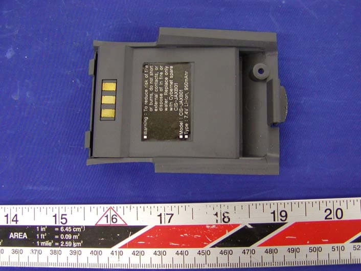
Click to zoom
Application Details
- Equipment Class
- PCB - PCS Licensed Transmitter
- Date of Grant
- May 23, 2004
- Application Purpose
- Original Equipment
- Date of Application
- May 23, 2004
- Equipment Note
- Wireless POS Terminal
- Frequency Range
- 1851.25000000 - 1908.75000000
- Company
- CyberNet Inc.
- Country
- South Korea
Documents & Files
Document Text
Text extracted from the exhibit documents filed with the FCC. Open a document above to read the original.
Users Manual
Installation Guide Prepared By: YH Song Doc Version: V1.2 Date Issued: July 24, 2003 JadeAIRE Installation Guide 24/07/03 Page 2 Version Modified By Modified Date Section Modified Reason Modified 1.2 CH Lee YH Song 24/07/03 All Original Table 1 - Document Control Information JadeAIRE Installation Guide 24/07/03 Page 3 Introduction The JadeAIRE Installation Guide is a complete guide on how to install and use CyberNet JadeAIRE wireless/mobile EFT-POS terminal. 1. Overview The JadeAIRE, the latest addition to the CyberNet product lines, is the most compact and stylish wireless/mobile payment terminal available in the market today. Featuring 32bit microprocessor, the JadeAIRE delivers the combination of the latest payment capabilities and the most sophisticated wireless technologies (GSM, GPRS and CDMA) to process payment anywhere, anytime by the merchants on the move. The JadeAIRE is comprised of handset and docking station. The handset can also be used as a mobile phone by plugging an earphone into the earphone jack located at the right side of the handset. 2. Selecting a location for your terminal 3 Select a location for your terminal that is both convenient for the operator and offers adequate ventilation and protection. The terminal should be mounted on a flat surface and in general, avoid areas with; - Excessive heat or dust - Oil moisture - Excessive electrical noise (caused by air conditioners, motors, fans or power tools, etc.) - Direct sunlight or artificial light that could reflect glare off the display panel JadeAIRE Installation Guide 24/07/03 Page 4 3. Unpacking Carefully inspect the shipping carton and its contents for shipping damage. If the terminal is damaged, file a claim immediately with the shipping company or carrier and notify CyberNet Inc. Do not use a damaged terminal. 1) Remove all the items from the carton. You should have; - The JadeAIRE terminal (handset + docking station) - Telephone cable (bundled if optional wired modem ordered) - Power pack with a cable - Paper roll - Battery - The JadeAIRE Installation Guide 2) Remove any protective wrapping from the terminal and place all the components on a table or counter. 3) Save the carton and packing material for repacking or moving the terminal in the future. JadeAIRE Installation Guide 24/07/03 Page 5 Installation Guide 1. List of contents - The JadeAIRE terminal (handset + docking station) - Telephone cable (bundled if optional wired modem ordered) - Power pack with a cable - Paper roll - Battery - The JadeAIRE Installation Guide Figure 1: Contents of The JadeAIRE package J A D E A I R E I n s t a l l a ti o n G u i d e JadeAIRE Installation Guide 24/07/03 Page 6 2. Icon descriptions JadeAIRE is capable of supporting both graphics and icons. Below is the list of icon descriptions. 1 2 3 4 5 6 Figure 2: JadeAIRE icons Icons Descriptions 1. Antenna reception signal level 2. Alarm 3. Incoming message (Voice or text message) 4. Menu scroll 5. Battery charge level 6. Current time 12 : 00 12 : 00 JadeAIRE Installation Guide 24/07/03 Page 7 3. Handset and docking station connections For connecting handset to docking station, simply place the handset on the docking station and slightly press it down until you hear a click. In order to remove the handset from the docking station, simultaneously press two clips placed on both side of the docking station and lift. Figure 3-1: Handset connection to docking station Figure 3-2: Handset removal from docking station JadeAIRE Installation Guide 24/07/03 Page 8 4. Power connections Before use, fully charge the battery (approximately 3 ~ 4 hours) bundled in the JadeAIRE package. When charging the battery, place the battery pack on the back of the handset and put the handset on the docking station as shown in Figure 4-1. Connect the DC adapter to the power cable. Plug the power cable into the electrical outlet and the opposing end into the DC jack on the back panel of the docking station. Use the power switch on the left of the docking station to power it on. When fully charged, the LED (Light Emitting Diode) on the bottom of the docking station turns green. Remove the handset from the docking station and switch the docking station off. Press F4 key for a few seconds to power the handset on. When using the JadeAIRE with the WIRED modem (33.6kbps/option) in the docking station, follow battery charging instructions provided above and keep the docking station powered on during all transactions. Figure 4-1: Battery installation/charge JadeAIRE Installation Guide 24/07/03 Page 9 Figure 4-2: Power connections z Warnings: Warnings must be followed as provided for the safety of the user and the equipment. - Always disconnect power to the JadeAIRE before connecting other ports or changing chips. - Do not use a DC adapter that did not come with the JadeAIRE. - Do not disassemble the DC adapter. Only a qualified service technician should service the adapter. - The DC adapter is designed for indoor use only. Do not expose to fluids or harsh environment including rain or snow. JadeAIRE Installation Guide 24/07/03 Page 10 5. Telephone line connections Telephone line connections are ONLY required for the JadeAIRE with the WIRED modem (33.6kbps/option) in the docking station. To eliminate the expense of setting up the additional phone line, two telephone ports are available on the JadeAIRE’s docking station as shown in Figure 5. Connect the one end of the incoming phone line into either of the interchangeable RJ-11 telephone ports. Insert provided telephone cable into the second port and the opposing end of the cable into a telephone. The use of a different/wrong cable may result in improper operation. Figure 5: Telephone line connections JadeAIRE Installation Guide 24/07/03 Page 11 6. Peripheral ports & interface contacts 6-1. Handset ports & contacts 1) Ports A port on the right side of the handset is a RS232 port for data transfer. For using this port, an optional RS232 cable (shown in Figure 6-1-…
Text truncated - open the document above for the full version.
Cover Letter(s)
CyberNet Inc. Corporate Headquarters CyberNet Inc R&D Center 6 th Floor, Sebang Bldg, #205, Lotte Suntech City, 708-8 Yoksamdong, Kangnamku, 513-15 Sangdaewondong, Chungwonku, Seoul, Korea Sungnamsi, Kyunggido, Korea Federal Communications Commission Authorization and Evaluation Division Confidentiality Request regarding application for certification of FCC ID: RXT-JADE-A1-CNN01 Pursuant to Sections 0.457 and 0.459 of the Commission’s Rules, we hereby request confidential treatment of information accompanying this application as outlined below: JadeAIRE CDMA Circuit Schematics JadeAIRE CDMA Circuit Description JadeAIRE CDMA Block Diagram JadeAIRE CDMA Parts List JadeAIRE CDMA H/W Specification The above materials contain trade secrets and proprietary information not customarily released to the public. The public disclosure of these materials may be harmful to the applicant and provide unjustified benefits to its competitors. The applicant understands that pursuant to Section 0.457 of the Rules, disclosure of this application and all accompanying documentation will not be made before the date of the Grant for this application. Sincerely, Seok Woo Kim / Director
External Photos
EXHIBIT C - EUT PHOTOGRAPHS EUT - Front View EUT – Rear View EUT – Back Side without Battery Docking unit - Top view Docking unit - Bottom view Docking unit - Connector view Battery – Top View Battery – Bottom View Earphone - Top View AC Adapter – Top View Serial cable – Top View I Serial cable – Top View II
ID Label/Location Info
EXHIBIT A - FCC ID LABELING AND WARNING STATEMENT Proposed FCC ID Label Specifications: Text is black or white in color and is left justified. Labels are silk-screened and shall be “permanently affixed” at a conspicuous location on the EUT. Proposed Label Location on EUT Front View of the EUT/Proposed ID Label Location FCC Warning Statement A FCC Warning Statement is provided in the product manual. FCC ID: RXT-JADE-AI-CNN01 FCC ID: RXT-JADE-A1-CNN01
Internal Photos
Chassis – Cover Off View EUT – Component View I EUT – Component View II EUT – Component View III Transceiver – Top View Transceiver – Bottom View Transceiver – Component View Transceiver – Solder View Transceiver - Shielding Off View I Transceiver - Shielding Off View II
Operational Description
Wireless Modem Test Procedure Press F4 key to turn on the device. After displaying CyberNet logo on LCD, press any key to go into the MAIN menu. To turn off the device, press F4 key and hold it down till the device is turned off. N O Setion Operations Display Check In idle mode (main menu), select “3. H/W module Test” by pressing KEY 3. JADE AIRE X1 CT1.20s 1. Loop Test 2. Burning Test 3. H/W moduleTest 4. Certification Test 5. H/W function Test 6. DSP module check 7. PINpad Program Test Select “6) Wireless Modem Test” by pressing KEY 6 JADE AIRE X1 CT1.20s 1) LCD Contrast 2) MSR 3) Printing Test 4) Set Time 5) IC/SAM Test 6) Wireless modem Test 7) Wired modem Test After displaying “CDMA initial....” and 4-digit counter, Wireless Modem Test menu is displayed. WIRELESS MODEM TEST 1: Input Number 2: Answer to ring 3: Voice call 4: Data call 5: Release call 6: Test Mode OK While initializing, power up to CDMA module and check its IDLE mode status. And send “AT\r” to the module 1 W I R E L E S S M O D E M T E S T * AT command to equivalent to each menu. 2: Answer to ring 3: Voice call 4: Data call 5: Release call 6: Test Mode 2: "AT$QCCAV\r" 3: "AT+CDV number\r" 4: "ATDT number\r" 5: "AT+CHV0\r" in voice DTR signal control in data 6: Enter min number mode How to enter MIN number to the module - Select KEY6 “Test Mode” to start test mode for being enable to enter the MIN number to the module. - Wait OK message displayed on the lowest column of LCD. And press any key to skip to next step. - Following "Input Your MIN number ", input the MIN number and ENTER for the module to test. - If showed “OK” message on the lowest column of LCD, press any key to make sure the number you entered by re-reading.. - After check the MIN number is correct or not, Go to the next step you want to do. How to make a voice call - Select KEY1 “ Input Number” for input the phone number you want to make. - Select KEY3 “Voice call” for starting to dial in Voice mode. How to make a data call - Select KEY1 “ Input Number” for input the phone number you want to make. - Select KEY4 “Data call” for starting to dial. In Data mode
Parts List/Tune Up Info
Tune up procedure To set up transmit power before shipping, AnyDATA uses a manufacturing process which is called “Calibration of Rx and Tx power over the dynamic range, temperature and frequency”. CDMA technical standard requires AnyDATA’s CDMA module to transmit more than +23dBm output power when it is required to transmit its maximum power. Therefore, AnyDATA sets the maximum power of the module to +24dBm (+/-) 1dB. By adjusting Tx AGC Amplifier built in the CDMA module, transmit power can be limited to +24dBm (+/-) 1dB. Transmit power calibration consists of transmit linearizer calibration, and power compensation calibration over the temperature and frequency. During the transmit linearizer calibration, the module searches for 16 AGC adjust values for the 16 power levels within the dynamic range including the maximum output power and saves these AGC adjust values in the memory device in the module. These searched AGC adjust values (TX_LIN_MASTER) set the maximum power of the module. To prevent the variation in maximum power over the frequency, the transmit circuit is calibrated over the frequency and compensation values (TX_LIM_VS_FREQ) are found. These values are also used to limit the maximum output power to +24dBm (+/-)1dB. Also to prevent the variation in maximum power over the temperature, the transmit circuit is calibrated over the temperature and compensation values (TX_LIM_VS_TEMP) are found. These are also used to limit the maximum output power to +24dBm (+/-)1dB when there is a variation in temperature..
RF Exposure Info
Note: This test report is specially limited to the above client company and the product model only. It may not be duplicated without prior written consent of Bay Area Compliance Laboratory Corporation. This report must not be used by the client to claim product endorsement by NVLAP or any agency of the U.S. Government. SAR EVALUATION REPORT For CyberNet Inc. 6 th Floor, Sebang Bldg.(New Bldg.) 708-8, Yoksamdong Kangnamku, Seoul, Korea FCC ID: RXT-JADE-AI-CNN01 2004-04-08 This Report Concerns: Original Report Equipment Type: Wireless POS Terminal Test Engineer: Daniel Deng/ Report No.: R0402192S Test Date: 2004-03-24/2004-03-30 Reviewed By: Ling Zhang/ Prepared By: Bay Area Compliance Laboratory Corporation (BACL) 230 Commercial Street Sunnyvale, CA 94085 Tel: (408) 732-9162 Fax: (408) 732 9164 CyberNet Inc. FCC ID: RXT-JADE-AI-CNN01 Report #R0402192S SAR Evaluation Report Page 2 of 85 TABLE OF CONTENTS SUMMARY....................................................................................................................................................................4 1 - REFERENCE ...........................................................................................................................................................5 2 - TESTING EQUIPMENT.........................................................................................................................................6 2.1 EQUIPMENTS LIST & CALIBRATION INFO...............................................................................................................6 2.2 EQUIPMENT CALIBRATION CERTIFICATE...............................................................................................................6 1900MHZ BODY LIQUID VALIDATION 3/30/2004...........................................................................................43 3 - EUT DESCRIPTION .............................................................................................................................................45 4 - SYSTEM TEST CONFIGURATION...................................................................................................................46 4.1 JUSTIFICATION.....................................................................................................................................................46 4.2 EUT EXERCISE PROCEDURE................................................................................................................................46 4.3 EQUIPMENT MODIFICATIONS...............................................................................................................................46 5 – CONDUCTED OUTPUT POWER MEASUREMENTS ...................................................................................47 5.1 PROVISION APPLICABLE.......................................................................................................................................47 5.2 TEST PROCEDURE................................................................................................................................................47 5.3 TEST EQUIPMENT.................................................................................................................................................47 5.4 TEST RESULTS.....................................................................................................................................................47 6 - DOSIMETRIC ASSESSMENT SETUP...............................................................................................................50 6.1 MEASUREMENT SYSTEM DIAGRAM.....................................................................................................................51 6.2. SYSTEM COMPONENTS........................................................................................................................................52 6.3 MEASUREMENT UNCERTAINTY............................................................................................................................56 7 - EVALUATION PROCEDURE.............................................................................................................................57 7.1 SAR EVALUATION PROCEDURE...........................................................................................................................57 7.2 EXPOSURE LIMITS................................................................................................................................................58 7.3 SIMULATED TISSUE LIQUID PARAMETER CONFIRMATION...................................................................................58 7.4 SAR MEASUREMENT...........................................................................................................................................58 7.5 SYSTEM ACCURACY VERIFICATION.....................................................................................................................59 7.6 LIQUID MEASUREMENT RESULT..........................................................................................................................60 8 - SAR TEST RESULTS............................................................................................................................................65 8.1 SAR BODY AND HEAD WORST-CASE TEST DATA...............................................................................................65 8.2 PLOTS OF TEST RESULT.......................................................................................................................................65 EXHIBIT A - SAR SETUP PHOTOGRAPHS .........................................................................................................72 RIGHT SIDE TOUCHING WITH PHANTOM....................................................................................................................72 BACK SIDE TOUCHING WITH PHANTOM..........................................................................................…
Text truncated - open the document above for the full version.
RF Exposure Info
CyberNet Inc. FCC ID: RXT-JADE-AI-CNN01 Report #R0402192S SAR Evaluation Report Page 43 of 85 1900MHZ Body Liquid validation 3/30/2004 Ambient Temp=23°C, Liquid Temp=22°C Frequency e' e'' 1850000000.0000 52.4321 13.9473 1852000000.0000 52.4198 13.9852 1854000000.0000 52.4436 14.0622 1856000000.0000 52.4452 14.0960 1858000000.0000 52.4475 14.1686 1860000000.0000 52.4495 14.1941 1862000000.0000 52.4737 14.2514 1864000000.0000 52.4854 14.3110 1866000000.0000 52.5256 14.3295 1868000000.0000 52.5089 14.3746 1870000000.0000 52.5152 14.4023 1872000000.0000 52.5087 14.4487 1874000000.0000 52.5153 14.5041 1876000000.0000 52.5486 14.5170 1878000000.0000 52.5552 14.5528 1880000000.0000 52.5644 14.5406 1882000000.0000 52.5312 14.5625 1884000000.0000 52.5472 14.5685 1886000000.0000 52.5362 14.5780 1888000000.0000 52.5388 14.5637 1890000000.0000 52.5166 14.5736 1892000000.0000 52.5048 14.5603 1894000000.0000 52.4533 14.5008 1896000000.0000 52.4694 14.4789 1898000000.0000 52.4183 14.4554 1900000000.0000 52.3974 14.4358 1902000000.0000 52.3991 14.3989 1904000000.0000 52.3759 14.3507 1906000000.0000 52.3245 14.3322 1908000000.0000 52.3413 14.2730 1910000000.0000 52.2964 14.2455 1912000000.0000 52.2410 14.1974 1914000000.0000 52.2327 14.1917 1916000000.0000 52.2246 14.1055 1918000000.0000 52.1892 14.0683 1920000000.0000 52.1607 14.0249 1922000000.0000 52.1507 14.0181 1924000000.0000 52.1320 13.9921 1926000000.0000 52.0671 13.9435 1928000000.0000 52.0776 13.9341 1930000000.0000 52.0707 13.9107 1932000000.0000 52.0146 13.8654 1934000000.0000 52.0228 13.8916 1936000000.0000 52.0097 13.8456 1938000000.0000 51.9800 13.8732 1940000000.0000 52.0174 13.8551 1942000000.0000 51.9879 13.8987 1944000000.0000 51.9617 13.8968 1946000000.0000 51.9704 13.9388 1948000000.0000 51.9409 13.9664 1950000000.0000 51.9493 13.9764 σ = ω ε o ε” = 2 π f ε o ε”=1.5259 where f = 835x 10 6 ε o = 8.854 x 10 -12 ε” = 14.4358 CyberNet Inc. FCC ID: RXT-JADE-AI-CNN01 Report #R0402192S SAR Evaluation Report Page 44 of 85 1900MHZ Head Liquid validation 3/30/2004 Ambient Temp=23 o C Liquid Temp=22 o C frequency e' e'' 1850000000.0000 38.9805 13.0699 1852000000.0000 38.9574 13.0555 1854000000.0000 38.9555 13.0547 1856000000.0000 38.9546 13.0438 1858000000.0000 38.9539 13.0195 1860000000.0000 38.9525 13.0238 1862000000.0000 38.9507 13.0138 1864000000.0000 38.9435 12.9969 1866000000.0000 38.9214 12.9617 1868000000.0000 38.9265 12.9629 1870000000.0000 38.9099 12.9564 1872000000.0000 38.8739 12.9760 1874000000.0000 38.8743 12.9403 1876000000.0000 38.8762 12.9188 1878000000.0000 38.8515 12.9395 1880000000.0000 38.8689 12.9307 1882000000.0000 38.8213 12.9295 1884000000.0000 38.7884 12.9214 1886000000.0000 38.7872 12.9331 1888000000.0000 38.7799 12.9777 1890000000.0000 38.7709 12.9398 1892000000.0000 38.7425 12.9460 1894000000.0000 38.7360 12.9696 1896000000.0000 38.7205 12.9576 1898000000.0000 38.6673 12.9920 1900000000.0000 38.6559 12.9817 1902000000.0000 38.6392 12.9834 1904000000.0000 38.6022 13.0248 1906000000.0000 38.6019 13.0156 1908000000.0000 38.5642 13.0222 1910000000.0000 38.5790 13.0587 1912000000.0000 38.5559 13.0584 1914000000.0000 38.5003 13.0799 1916000000.0000 38.5287 13.1355 1918000000.0000 38.5077 13.1285 1920000000.0000 38.5017 13.1545 1922000000.0000 37.4882 13.1716 1924000000.0000 37.4952 13.1919 1926000000.0000 37.4908 13.2166 1928000000.0000 37.4531 13.2438 1930000000.0000 37.4568 13.2416 1932000000.0000 37.4362 13.2648 1934000000.0000 37.4359 13.2759 1936000000.0000 37.4288 13.3031 1938000000.0000 37.4237 13.3386 1940000000.0000 37.4500 13.3328 1942000000.0000 37.4271 13.3225 1944000000.0000 37.4450 13.3489 1946000000.0000 37.4401 13.3844 1948000000.0000 37.4341 13.3701 1950000000.0000 37.4631 13.3973 σ = ω ε o ε” = 2 π f ε o ε”=1.3722 where f = 835x 10 6 ε o = 8.854 x 10 -12 ε” = 12.9817 CyberNet Inc. FCC ID: RXT-JADE-AI-CNN01 Report #R0402192S SAR Evaluation Report Page 45 of 85 3 - EUT DESCRIPTION Applicant: CyberNet Inc Product Description: Wireless POS Terminal Product Model Number: J a d e A I R E C D M A FCC ID: RXT-JADE-AI-CNN01 Serial Number: DM04010002 Maximum RF Output Power: 25.17dBm RF Exposure environment: General Population/Uncontrolled Applicable Standard FCC CFR 47, Part 22, Part 24 Application Type: Certification CyberNet Inc. FCC ID: RXT-JADE-AI-CNN01 Report #R0402192S SAR Evaluation Report Page 46 of 85 4 - SYSTEM TEST CONFIGURATION 4.1 Justification The system was configured for testing in a typical fashion (as normally used by a typical user). 4.2 EUT Exercise Procedure The EUT exercising program used during SAR testing was designed to exercise the various system components in a manner similar to a typical use. 4.3 Equipment Modifications No modification(s) were made to ensure that the EUT complies with the applicable limits. CyberNet Inc. FCC ID: RXT-JADE-AI-CNN01 Report #R0402192S SAR Evaluation Report Page 47 of 85 5 – CONDUCTED OUTPUT POWER MEASUREMENTS 5.1 Provision Applicable According to FCC §22.913 (a), the ERP of mobile transmitters and auxiliary test transmitters must not exceed 7 watts. According to FCC § 24.232(b), EIRP peak power for mobile/portable stations are limited to 2 watts. 5.2 Test Procedure The RF output of the transmitter was connected to the input of the spectrum analyzer through sufficient attenuation. 5.3 Test equipment Hewlett Packard HP8564E Spectrum Analyzer, Calibration Due Date: 2004-08-25. Hewlett Packard HP 7470A Plotter, Calibration not required. A.H. Systems SAS200 Horn Antenna, Calibration Due Date: 2004-08-01 Com-Power AD-100 Dipole Antenna, Calibration Due Date: 2004-09-26 5.4 Test Results 800 MHz Modulation Type Channel Frequency (MHz) Output Power in dBm Output Power in W Limit (W) Low 824.73 25.00 0.316 7 Middle 836.43 25.17 0.329 7 CDMA High 848.24 24.83 0.304 7 1900 MHz Modulation Type Channel Frequency (MHz) Output Power in dBm Output Power in W Limit (W) Low 1851.12 24.67 0.293 7 Middle 1879.87 24.83 0.304 7 CDMA High 1908.53 24.83 0.304 7 Please refer to the…
Text truncated - open the document above for the full version.
Test Report
Note: This test report is specially limited to the above client company and the product model only. It may not be duplicated without prior written consent of Bay Area Compliance Laboratory Corporation. This report must not be used by the client to claim product endorsement by NVLAP or any agency of the U.S. Government. FCC PART 22, 24 TYPE APPROVAL EMI MEASUREMENT AND TEST REPORT For CyberNet Inc. 6 th Floor, Sebang Bldg.(New Bldg.) 708-8, Yoksamdong Kangnamku, Seoul, Korea FCC ID: RXT-JADE-AI-CNN01 2004-04-08 This Report Concerns: Original Report Equipment Type: Wireless POS Terminal Test Engineer: Ling Zhang / Report No.: R0402192 Test Date: 2004-03-24 Reviewed By: Ming Jing / Prepared By: Bay Area Compliance Laboratory Corporation (BACL) 230 Commercial Street Sunnyvale, CA 94085 Tel: (408) 732-9162 Fax: (408) 732 9164 CyberNet Inc. FCC ID: RXT-JADE-AI-CNN01 Report # R0402192 Page 2 of 45 FCC Part 22, 24 Type Approval Report TABLE OF CONTENTS GENERAL INFORMATION.......................................................................................................................................4 PRODUCT DESCRIPTION FOR EQUIPMENT UNDER TEST (EUT) ....................................................................................4 OBJECTIVE...................................................................................................................................................................4 RELATED SUBMITTAL(S)/GRANT(S).............................................................................................................................4 TEST METHODOLOGY..................................................................................................................................................4 TEST FACILITY.............................................................................................................................................................4 SYSTEM TEST CONFIGURATION ..........................................................................................................................6 JUSTIFICATION.............................................................................................................................................................6 BLOCK DIAGRAM.........................................................................................................................................................6 EQUIPMENT MODIFICATIONS.......................................................................................................................................6 SUPPORT EQUIPMENT LIST AND DETAILS....................................................................................................................6 EXTERNAL I/O CABLING LIST AND DETAILS...............................................................................................................6 POWER SUPPLY INFORMATION.....................................................................................................................................6 TEST SETUP BLOCK DIAGRAM.....................................................................................................................................7 SUMMARY OF TEST RESULTS ...............................................................................................................................8 §2.1047 - MODULATION CHARACTERISTIC .......................................................................................................9 APPLICABLE STANDARD..............................................................................................................................................9 TEST PROCEDURE........................................................................................................................................................9 TEST EQUIPMENT LIST AND DETAILS...........................................................................................................................9 ENVIRONMENTAL CONDITIONS....................................................................................................................................9 TEST RESULTS.............................................................................................................................................................9 §2.1053 - SPURIOUS RADIATED EMISSIONS .....................................................................................................13 APPLICABLE STANDARD............................................................................................................................................13 TEST PROCEDURE......................................................................................................................................................13 TEST EQUIPMENT LIST AND DETAILS.........................................................................................................................13 ENVIRONMENTAL CONDITIONS..................................................................................................................................13 TEST RESULT.............................................................................................................................................................14 §1.1307(B)(1) & §2.1093 - RF EXPOSURE...............................................................................................................17 §2.1046, §22.912(D), & §24.232 - RF POWER OUTPUT ........................................................................................19 APPLICABLE STANDARD............................................................................................................................................19 TEST PROCEDURE......................................................................................................................................................19 TEST EQUIPMENT LIST AND DETAILS.................................................................................................…
Text truncated - open the document above for the full version.
Test Report
CyberNet Inc. FCC ID: RXT-JADE-AI-CNN01 Report # R0402192 Page 21 of 45 FCC Part 22, 24 Type Approval Report §2.1046, §2…
Text truncated - open the document above for the full version.
Contact Information
Applicant
Changho Lee(Research Engineer)
Test Firm
Bay Area Compliance LaboratoryJohn Chan
Technical Specifications
| # | Rule Parts | Frequency Range | Power Output | Emission | Tolerance |
|---|---|---|---|---|---|
| 2 | 24E | 1.85 GHz - 1.91 GHz | 304.00 mW | 1M29F9W | 2.5 ppm |