RXWWHP175900MHz Transmitter
TWD Acoustic Products Limited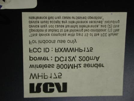
Click to zoom
Application Details
- Equipment Class
- DXX - Part 15 Low Power Communication Device Transmitter
- Date of Grant
- Jun 20, 2004
- Application Purpose
- Original Equipment
- Date of Application
- Jun 20, 2004
- Equipment Note
- 900MHz Transmitter
- Frequency Range
- 911.90000000 - 913.30000000
- Country
- China
Documents & Files
Document Text
Text extracted from the exhibit documents filed with the FCC. Open a document above to read the original.
Users Manual
WHP170/WHP175 * Range may vary by environment.* La portée peut varier selon l'environnement.* El alcance puede variar según el entorno. 900MHz Wireless HeadphonesCasque sans fil à émetteur de 900 MHzAudífonos inalámbricos con transmisorde 900 MHz Transmits stereo signal even outside your home!Émet un signal stéréo même à l'extérieur de la maison!¡Transmite señal estereofónicaincluso afuera de su casa! WHP170_US_IB_REV.qxd 12/24/03 11:22 AM Page 1 HEADSET SAFETYFollow these precautions for safe usage of your wireless headphones.1. These wireless headphones have been designed for residential use and should not be used for industrial purposes. The headphonesshould be installed and used in accordance with the instructionscontained in this manual. 2. Read through these instructions completely before installation. Follow the instructions carefully and carry them out in the correctorder. Keep the manual on hand for future reference. 3. The power for this headphone system is delivered with batteries. Before charging, read the instructions in this manual. Disconnect the power supply from the recharging cradle/transmitter beforeinstalling or removing batteries. 4. Always leave easy access to the main power supply.5. Disconnect the unit from the main power supply during storms, or if you will be absent for a long period of time. 6. If you observe smoke or detect a burning odor, immediately disconnect the device from the main power supply. 7. Never open the unit yourself; you may receive a severe electric shock, leading to serious injury or even death. 8. Protect the unit from dust, humidity and sources of excessive heat (e.g., fireplace or radiator). 9. The power source should not be in contact with liquids or exposed to the risk of dripping or splashing liquid. Be careful not to place the power source or recharging cradle/transmitter near any objectcontaining liquid (e.g., a vase, glass or bottle). 10.Do not expose the unit to direct sunlight. Its maximum ambient temperature is 95° Fahrenheit (35° Celsius). 11. The ventilation should not be impeded by covering the unit with any items, such as newspapers, tablecloths, curtains, etc. 12.No flame sources, such as lighted candles, should be placed on or close to the recharging cradle/transmitter. 13.This unit has been designed for use in a dry environment. If, for exceptional reasons, you must utilize the unit out of doors (balcony,veranda, etc.), take care to protect it from dampness (dew, rain or splashes of liquid). 14.The maximum ambient humidity that the device supports is 85 percent. If the unit is cold and you wish to use it in a warm room,wait until any condensation on the unit evaporates by itself beforeyou turn it on. WHP170_US_IB_REV.qxd 12/24/03 11:22 AM Page 2 HEADSET SAFETY (continued)15.Clean the unit with a soft cloth soaked in a neutral detergent. You may damage the unit if you use an alcohol-based product. If you are unsure if the detergent is alcohol-based, test the cleaningproduct on the underside of the unit. Thomson Inc. declines all liability for any use that does not comply with the instructions in this User’s Manual. Keep your sales receipt to obtain warranty parts and service and for proof of purchase. Attach it here and record the serial and modelnumbers. These numbers are located on the product. Model No.______________________Serial No. ______________________Purchase Date: __________________Dealer/Address/Phone: ____________________________________ __________________________________________________________ TABLE OF CONTENTSIntroduction . . . . . . . . . . . . . . . . . . . . . . . . . . . . . . . . . . . . . . . . . . . . . . . .4Features . . . . . . . . . . . . . . . . . . . . . . . . . . . . . . . . . . . . . . . . . . . . . . . . . . .4Headphone Set Description . . . . . . . . . . . . . . . . . . . . . . . . . . . . . . . . . . .5Recharging the Headset . . . . . . . . . . . . . . . . . . . . . . . . . . . . . . . . . . . . . .6Recharging Cradle/Transmitter Description . . . . . . . . . . . . . . . . . . . . . .6Supplied Accessories . . . . . . . . . . . . . . . . . . . . . . . . . . . . . . . . . . . . . . . . .7Battery Installation and Information Installing the Rechargeable Batteries . . . . . . . . . . . . . . . . . . . . . . . . . .7Charging the Rechargeable Batteries . . . . . . . . . . . . . . . . . . . . . . . . . .8NiMH Rechargeable Battery Memory Effect . . . . . . . . . . . . . . . . . . . .8NiMH Natural Power Discharge . . . . . . . . . . . . . . . . . . . . . . . . . . . . .8NiMH Battery Warning . . . . . . . . . . . . . . . . . . . . . . . . . . . . . . . . . . . . .8 Connecting the Recharging Cradle/Transmitter . . . . . . . . . . . . . . . . . .9Operation Standard Usage . . . . . . . . . . . . . . . . . . . . . . . . . . . . . . . . . . . . . . . . . . . .9 Alternate Installation Configuration . . . . . . . . . . . . . . . . . . . . . . . . . .10 Troubleshooting . . . . . . . . . . . . . . . . . . . . . . . . . . . . . . . . . . . . . . . . . . . .11Specifications . . . . . . . . . . . . . . . . . . . . . . . . . . . . . . . . . . . . . . . . . . . . . .13Warranty . . . . . . . . . . . . . . . . . . . . . . . . . . . . . . . . . . . . . . . . . . . . . . . . . .14 WHP170_US_IB_REV.qxd 12/24/03 11:22 AM Page 3 4 FEATURES900 MHz RF technology lets you roam freely throughout your houseOperating distance up to 150 feet/45 meters from cradle/transmitter*No line-of-sight limitationsConvenient power, volume and tuning controls located on headphones* Range may vary by environment. INTRODUCTIONCongratulations on your purchase of this wireless headphone system. The WHP170/WHP175 utilizes wireless, radio frequencytransmission (900 MHz). The headphones are induction rechargedusing an electric field and incorporate Phase Lock Loop (PLL)technology, which offers three channels for radio transmissions. This 900 MHz stereo wireless headphone system features a compactdesign that enables you to enjoy music and TV sound just …
Text truncated - open the document above for the full version.
Block Diagram
123456 A B C D 654321 D C B A Title NumberRevisionSize C Date:2-Apr-2032 Sheet of File:N:\rd\Model_2003\WHP-175\Spec_whp-175\Output_WHP-175\SCH-PCB_WHP-175l\SCH-PCB drawing_WHP-175\whp175.DdbDrawn By: CHANNEL SELECT REF XTAL 10MHz PLL SIT8825 buffer VCO 912MHz Driver PA 912MHz ANT L R Buffer Mix PRE-AMP 38KHz CPU Line Input L R Charge section Charge control Charge detection PDF created with FinePrint pdfFactory trial version http://www.pdffactory.com
External Photos
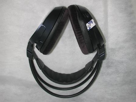
INTERTEK TESTING SERVICE Report no.: 04058791 FCC ID: RXWWHP175 Equipment Photographs Model : WHP-175 (External) INTERTEK TESTING SERVICE Report no.: 04058791 FCC ID: RXWWHP175 Equipment Photographs Model : WHP-175 (External) INTERTEK TESTING SERVICE Report no.: 04058791 FCC ID: RXWWHP175 Equipment Photographs Model : WHP-175 (External)
ID Label/Location Info
4 1 cm 48cm Label location
Internal Photos
INTERTEK TESTING SERVICE Report no.: 04058791 FCC ID: RXWWHP175 Equipment Photographs Model : WHP-175 (Internal) INTERTEK TESTING SERVICE Report no.: 04058791 FCC ID: RXWWHP175 Equipment Photographs Model : WHP-175 (Internal) INTERTEK TESTING SERVICE Report no.: 04058791 FCC ID: RXWWHP175 Equipment Photographs Model : WHP-175 (Internal) INTERTEK TESTING SERVICE Report no.: 04058791 FCC ID: RXWWHP175 Equipment Photographs Model : WHP-175 (Internal) INTERTEK TESTING SERVICE Report no.: 04058791 FCC ID: RXWWHP175 Equipment Photographs Model : WHP-175 (Internal) INTERTEK TESTING SERVICE Report no.: 04058791 FCC ID: RXWWHP175 Equipment Photographs Model : WHP-175 (Internal) INTERTEK TESTING SERVICE Report no.: 04058791 FCC ID: RXWWHP175 Equipment Photographs Model : WHP-175 (Internal) INTERTEK TESTING SERVICE Report no.: 04058791 FCC ID: RXWWHP175 Equipment Photographs Model : WHP-175 (Internal) INTERTEK TESTING SERVICE Report no.: 04058791 FCC ID: RXWWHP175 Equipment Photographs Model : WHP-175 (Internal)
Operational Description
Wireless 912 Headphone With PLL Transmitter WHP-175 RF Headphone System WHP-175 THOMSON wire-less system The RF/FM headphone system WHP-175 consists of a transmitter in a desk-top sized housing and a receiver unit which is incorporated in a headphone. The transmitter has the possibility be connected to any sound source by a HiFi connecting cable. Sound sources intended to be used are: E.g. CD, HiFi audio systems, TV and multi media sound. The system is intended to be used around the house. Transmitter The transmitter is a stand alone product, with a rectangular sized box with built in antenna. The box contains the printed circuit board a conducted charger. A channel knob is integrated in the housing. Circuit description The stereo audio input signal is amplified and passing an Automatic Level Control circuit. This makes the input signal for further processing independent from input levels of the sound source. Before the signal is pre-emphasized is passing an impedance matching circuit to avoid to be a too big load for he amplifier. In the next step the stereo signal is multiplexed and modulated (IC: NJM2035). In the Tx module the signal is mixed with the RF oscillator signal. The RF oscillator frequency is PLL in order to obtain a steady RF output signal. (911.95MHz,912.65MHz,913.35MHz). The RF signal is amplified and loaded by the antenna. PDF created with FinePrint pdfFactory trial version http://www.pdffactory.com
Schematics
123456 A B C D 654321 D C B A Title NumberRevisionSize B Date:31-Mar-2004Sheet of File: N:\rd\Model_2003\WHP-170\Spec_WHP-170\Output_WHP-170\SCH-PCB_WHP-170\SCH-PCB drawing_WHP-170\whp170-Pr-022404.DDBDrawn By: RT6 22 QD13 MJE3055T RT8 330R RT7 4.7k DD2 1N4001 RT9 10k RT3 47k RT4 180R CT15 2.7p CD12 0.1u/250V CT16 2p CT17 1.8p CT18 2.2p CT13 220p CT14 2p DT1 BB535 CT12 100u/10V CT6 100u/10V QT2 2SC4226-R25 CT9 4.7P CU10 12p CT10 10P CT11 220p TP1 TP2 CT8 220p SW101 CHG(on/off) CA10 4u7(0805) CA1 4u7(0805) CA14 4u7(0805) CA6 4u7(0805) CU5 2u2(0805) VCC 2 CP1 3 GND 4 LD 5 CK 6 DATA 7 STN 8 FIN1 1 BO 9 XOUT 10 XIN 11 SW 12 GND 13 CP2 14 VCC 15 FIN2 16 U1 KB8825 RT5 150R RU18 10k RU19 47k CU4 10n CU6 2n2 CU7 5n6 CT19 220p RU17 4k7 YU1 10.000MHz TCU1 1-10p CU3 100n CU8 22p CU9 10p CA25 560p VCC2 RU20 22k CU2 1n LT6 COIL RF2 RT12 5.1K RT13 1K QA3 BC817 VCC1 RESET 1 2 3 4 5 6 7 8 9 10 11 12 13 14 U2 3C72N2 CU1 100n CU15 10n RU16 56R VCC3 VCC3 QT3 2SC4226-R25 QT1 2SC4226-R25 CH-1 IN 1 NC 2 BYPASS 3 GND 4 BYPASS 5 XTAL 6 CAP 7 PL OUT 8 MPX OUT 9 V+ 10 TRIM 1 11 TRIM 2 12 NC 13 CH-2 IN 14 U3 NJM2035 RT10 1.5K RT11 22K RA23 1.8k RA24 10k RA26 2.2k RA19 270R RA20 270R RA21 100R CA21 10p CA20 100p YA1 38kHz CA19 10u RA22 10R CA22 100n CA23 100u/10V CA27 8n2 CT20 1uF RD14 10K CA26 22n RD152K2 RD13 10K RD12 3k3 ZD3 9V1 ZENER QD8 BC817 QD9 BC807 LINE IN (R)LINE IN (L) LT3 LT2 .5T LT1 .5T CT3 8p CT2 3.9P RU8 47K J1 SMA CD8 100n ZD1 3V9 ZENER QD10 SS8050D RU7 10k RU13 10k CT5 220p RT2 100R RT1 18k CT4 5.6P CA9 100n 3 1 2 PA2 50KB SONG-ZHI-YANG VCC2 A/0 VI 1 G N D 2 VO 3 UD1 78L06 Samsung 1 2 HD1 DC JACK 911.95MHz/912.65MHz/913.35MHz CD3 10u/10V CD2 100n CD4 100n N F 1 1 I N 1 2 O U T 1 3 G N D 4 A L C 5 V C C 6 O U T 2 7 I N 2 8 N F 2 9 U6 LS22241 RA3 3k3 RA2 100k RA1 10k RA12 3k3 RA11 100k RA10 10k RA8 330k CA7 47u/16V CA8 100u/10V CA3 10n CA11 10n CA4 8n2 CA12 8n2 RA5 56k RA14 56k CA5100n CA13 100n QU1 BC817 QU2 BC807 RU15 22k RU14 2.2k RU12 10k VCC3 RU4 33K RU210K RU3 10K RA18 47K QD7 B C 8 1 7 RA17 47k SU1 SW 2P2T VCC3 RA9 10R RA4 47k DD1 1N4001 RA13 47k CA24 1uF QD12 SS8550D CT1 100p VCC1 RA31 1R QD4 SS8050D 31 2 PA1 50k POT RU5 100k QA1 BC817 C202 33p QA2 BC817 C201 33p RA29 18k Y4 4.19MHz RA30 680k V C C 3 RA32 15k RA28 750k RA27 1.5k CA28 1u CA29 1u CA30 68p CA2 68p CA31 220n Headphone Transmitter RU6 22k RD3 3k3 RD2 33k VCC1 QD2 BC807 VCC1 RD8 10K 1 2 3 HA1 STEREO JACK 3P RD16 1k RU11 47k RU10 47k RU9 47k LED1 GREEN ZD2 3V9 ZENER RD9 1K CHANNEL RA6 100 RA15 100 RA25 68k RA7 1k5 CA16 10u/10V RA16 1k5 CA18 10u/10V CA15 10u/10V CA17 10u/10V LT5 8n2H RU21 47K CD5 10u/10V VCC2 RD5 680R RD4 180R 1 3 LA1 10mH QD3 BC817 LT4 3n3H 1.5T, D1.2, Dw0.3 CT7 3.3P CD11 15n RD10 6.8K 1 2 3 4 LD2 580uH CD6 100n QD1 SS8550D RD202.7K DS-020 WHP175-TX-022404 Induction charger QD6 BC817 QD5 BC817 RD191k RD1868k CU11 0R CU12 0R CU13 150p DU6 DU1 LA2 5T CU14 0R CU16 150p CU18 150p CU21 150p CU22 150p CU23 150p RD24 0R RD17 0R LA01 18uH(1008) CAA02 470p CAA01 470p L A 0 2 1 8 u H ( 1 0 0 8 ) CAA04 470p CAA03 470p LA03 2.7uH(0805) CAA06 470p CAA05 1n CAA07 470p DA1 1N4001 VCC3 1/2 CCA06 33P O s c F r e q u e n c y = 7 0 K H z A m p l i t u d e = 2 3 V p - p RF Amplifier PDF created with FinePrint pdfFactory trial version http://www.pdffactory.com
Test Report
Intertek Testing Services Hong Kong Ltd. 2/F., Garment Centre, 576 Castle Peak Road, Kowloon, Hong Kong. Tel: (852) 2173 8888 Fax: (852) 2785 5487 Website: www.hk.intertek-etlsemko.com May 13, 2004 TWD Acoustic Products Ltd. Unit A ~ B, 5/F., Por Yen Building, 478 Castle Peak Road, Kowloon, Hong Kong. Dear Miss Monica Chan: Enclosed you will find your file copy of a Part 15 report (FCC ID: RXWWHP175). For your reference, TCB will normally take another 15-20 days for reviewing the report. Approval will then be granted when no query is sorted. Please contact me if you have any questions regarding the enclosed material. Sincerely, Billy Chow Senior Supervisor Signed for and on behalf of Intertek Hong Kong ETL SEMKO Enclosure FCC ID: RXWWHP175 • The test results reported in this test report shall refer only to the sample actually tested and shall not refer or be deemed to refer to bulk from which such a sample may be said to have been obtained. • This report shall not be reproduced except in full without prior authorization from Intertek Testing Services Hong Kong Limited • For Terms And Conditions of the services, it can be provided upon request. • The evaluation data of the report will be kept for 3 years from the date of issuance. Intertek Testing Services Hong Kong Ltd. 2/F., Garment Centre, 576 Castle Peak Road, Kowloon, Hong Kong. Tel: (852) 2173 8888 Fax: (852) 2785 5487 Website: www.hk.intertek-etlsemko.com TWD Acoustic Products Ltd. Application For Certification (FCC ID: RXWWHP175) Transmitter WO# 04058791 LC/el May 13, 2004 FCC ID: RXWWHP175 INTERTEK TESTING SERVICES FCC ID: RXWWHP175 i LIST OF EXHIBITS INTRODUCTION EXHIBIT 1: General Description EXHIBIT 2: System Test Configuration EXHIBIT 3: Emission Results EXHIBIT 4: Equipment Photographs EXHIBIT 5: Product Labelling EXHIBIT 6: Technical Specifications EXHIBIT 7: Instruction Manual EXHIBIT 8: Miscellaneous Information INTERTEK TESTING SERVICES FCC ID: RXWWHP175 ii MEASUREMENT/TECHNICAL REPORT TWD Acoustic Products Ltd. - MODEL: RCA WHP175 FCC ID: RXWWHP175 This report concerns (check one:) Original Grant X Class II Change _____ Equipment Type: Low Power Transmitter (example: computer, printer, modem, etc.) Deferred grant requested per 47 CFR 0.457(d)(1)(ii)? Yes No X If yes, defer until: date Company Name agrees to notify the Commission by: date of the intended date of announcement of the product so that the grant can be issued on that date. Transition Rules Request per 15.37? Yes No X If no, assumed Part 15, Subpart C for intentional radiator - the new 47 CFR [12-08- 03 Edition] provision. Report prepared by: Billy Chow Intertek Testing Services Hong Kong Ltd. 2/F., Garment Centre, 576, Castle Peak Road, Kowloon, Hong Kong Phone: 852-2173-8545 Fax: 852-2371-0914 INTERTEK TESTING SERVICES FCC ID: RXWWHP175 iii Table of Contents 1.0 General Description................................................................................................. 3 1.1 Product Description............................................................................................... 3 1.2 Related Submittal(s) Grants .................................................................................. 3 1.3 Test Methodology................................................................................................. 4 1.4 Test Facility .......................................................................................................... 4 2.0 System Test Configuration ...................................................................................... 6 2.1 Justification ........................................................................................................... 6 2.2 EUT Exercising Software ...................................................................................... 6 2.3 Special Accessories.............................................................................................. 6 2.4 Equipment Modification......................................................................................... 7 2.5 Support Equipment List and Description................................................................ 7 2.6 Measurement Uncertainty ..................................................................................... 7 3.0 Emission Results ..................................................................................................... 9 3.1 Field Strength Calculation .................................................................................. 10 3.1 Field Strength Calculation (cont’d) ..................................................................... 11 3.2 Radiated Emission Configuration Photograph................................................... 12 3.3 Radiated Emission Data .................................................................................... 13 3.4 Conducted emission Configuration Photograph................................................. 16 3.5 Conducted Emission Date................................................................................. 18 4.0 Equipment Photographs............................................................................................. 20 5.0 Product Labelling ................................................................................................... 22 6.0 Technical Specifications ........................................................................................ 24 7.0 Instruction Manual ................................................................................................. 26 8.0 Miscellaneous Information .................................................................................... 28 8.1 Measured Bandwidth................................................................................................ 29 8.2 Discussion of Pulse Desensitization .................................................................... 30 8.3 Calculation of Average Factor .................................................................…
Text truncated - open the document above for the full version.
Test Report
INTERTEK TESTING SERVICE Report No:04058791 FCC ID: RXWWHP175 Configuration Photographs Worst-Case Line-Conducted Emissions (Front View) Model : WHP-175 Fig.3 INTERTEK TESTING SERVICE Report No:04058791 FCC ID: RXWWHP175 Configuration Photographs Worst-Case Line-Conducted Emissions (Back View) Model : WHP-175 Fig.4 INTERTEK TESTING SERVICE Report No:04058791 FCC ID: RXWWHP175 Configuration Photographs Worst-Case Line-Conducted Emissions (Side View) Model : WHP-175 Fig.5
Test Setup Photos
INTERTEK TESTING SERVICE Report No:04058791 FCC ID: RXWWHP175 Configuration Photographs Worst-Case Radiated Emissions (Front View) Model : WHP-175 Fig.1 INTERTEK TESTING SERVICE Report No:04058791 FCC ID: RXWWHP175 Configuration Photographs Worst-Case Radiated Emissions (Back View) Model : WHP-175 Fig.2
Contact Information
Applicant
Monica Chan
Technical Contact
Intertek Testing Services Hong Kong Ltd.Alfred Lo
[email protected]852-2173-8545
2/F., Garment Centre · Kowloon, · Hong Kong
Non-Technical Contact
Intertek Testing Services Hong Kong Ltd.Alfred Lo
[email protected]852-2173-8545
Test Firm
Intertek Testing Services Hong KongBilly Chow
Technical Specifications
| # | Rule Parts | Frequency Range | Power Output |
|---|---|---|---|
| 1 | 15C | 911.9 MHz - 913.3 MHz | - |
Other Applications from TWD Acoustic Products Limited
RXWWHP175RX
Jun 15, 2004900MHz Scanning Receiver
Equipment Class
CSR - Scanning Receiver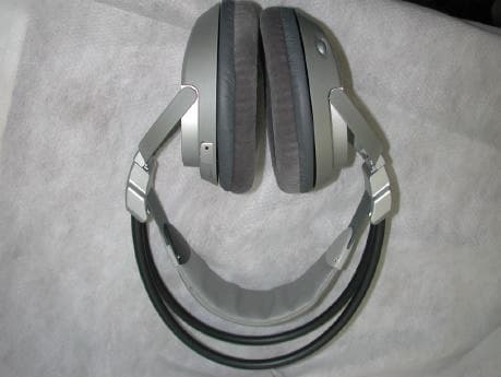
RXWWHP170RX
May 18, 2004900MHz Wireless Headphone
Equipment Class
CYY - Communications Receiver used w/Pt 15 Transmitter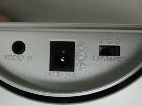
RXWWHP170
May 13, 2004Induction Charger
Equipment Class
8CC - Part 18 Consumer Device