RYP12121Wireless USB-link for heart rate monitoring
Suunto Oy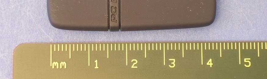
Click to zoom
Application Details
- Equipment Class
- DXT - Part 15 Low Power Transceiver, Rx Verified
- Date of Grant
- May 23, 2006
- Application Purpose
- Original Equipment
- Date of Application
- May 23, 2006
- Equipment Note
- Wireless USB-link for heart rate monitoring
- Frequency Range
- 2465.00000000 - 2465.00000000
- Company
- Suunto Oy
- Country
- Finland
Documents & Files
Document Text
Text extracted from the exhibit documents filed with the FCC. Open a document above to read the original.
Users Manual
CUSTOMER SERVICE CONTACTS Suunto OyPhone+358 9 875870 Fax+358 9 87587301 Suunto USAPhone1 (800) 543-9124 CanadaPhone1 (800) 776-7770 European Call CenterPhone +358 2 284 11 60 Suunto Website www.suunto.com EN TABLE OF CONTENTS 1. INTRODUCTION TO SUUNTO PC POD ..............................................................3 2. ATTACHING SUUNTO PC POD ...........................................................................3 3. POSITIONING SUUNTO PC POD ........................................................................4 4. OPERATION .........................................................................................................4 5. SUUNTO SOFTWARE ..........................................................................................5 5.1. REAL-TIME ANALYSIS - SUUNTO MONITOR ........................................... 5 5.2. DEEPER ANALYSIS - SUUNTO TRAINING MANAGER ............................ 5 6. INSTALLING SUUNTO SOFTWARE ....................................................................6 6.1. INSTALLING THE SOFTWARE .................................................................. 6 6.2. INSTALLING THE USB DRIVERS .............................................................. 6 6.3. INSTALLING SUUNTO SPORTS INSTRUMENT ON WINDOWS 2000/XP .............................................................................. 6 7. TECHNICAL SPECIFICATIONS ...........................................................................7 8. INTELLECTUAL PROPERTY ...............................................................................7 8.1. COPYRIGHT................................................................................................ 7 8.2. TRADEMARK .............................................................................................. 7 8.3. PATENT ....................................................................................................... 7 9. DISCLAIMERS ......................................................................................................7 9.1. USER’S RESPONSIBILITY ......................................................................... 7 9.1.1. CE .....................................................................................................7 9.2. FCC COMPLIANCE ..................................................................................... 8 9.3. LIMITS OF LIABILITY AND ISO 9001 COMPLIANCE ................................ 8 9.4. AFTER SALES SERVICE ............................................................................ 8 10. DISPOSAL OF THE DEVICE .............................................................................9 3 1. INTRODUCTION TO SUUNTO PC POD Suunto PC Pod is a Peripheral Observation Device designed to receive heart rate (HR) data wirelessly from your heart rate transmitter belt straight to your PC. This allows you or your coach to monitor your performance, in real time, on the PC screen. Additionally, the Suunto PC POD further enhances the functionality of other ANT-equipped wireless devices. Suunto PC Pod's wireless connection, with a range of 10 meters/33 feet, allows you to send your training data from the HR belt to your PC digitally, using ANT transmission tech- nology, which eliminates interference from other devices in the vicinity. This means that even when using the PC Pod at the gym or other public place, you can be sure that the information you receive is accurate and personal. Thanks to the individually identifiable Suunto ANT heart rate belts, the PC Pod can be used to receive up to three peoples' heart rates simultaneously. Suunto PC Pod makes a new type of training control possible. For a variety of applications, viewing and analyzing your training data in real time, without having to wait until you're fin- ished, becomes a convenient and practical possibility. At home or at the gym, on an exer- cise bike or rowing machine, for example, you can visually keep track of the effectiveness of your session by following your progress on your PC screen. 2. ATTACHING SUUNTO PC POD Suunto PC Pod is quick and easy to attach. Simply take off the cover, plug it into your PC's USB port and you're ready to go. 4 3. POSITIONING SUUNTO PC POD To achieve the best readings from the HR belts, it is important to position the PC Pod cor- rectly. Ideally, the PC Pod should point towards the area that is to be monitored. 4. OPERATION Under normal circumstances, the receiver has a range of 10 meters/33 feet, but factors that interfere with transmission from the HR belts - such as humidity and obstacles like training equipment or walls - can affect the range. As a 2.4 GHz signal does not go through water and there- fore neither through the human body, the transmission from the HR belt is hindered if the monitored athlete is facing away from the Suunto PC Pod, so there may be disruptions in the recording of the HR signal. For the same reason, the Suunto PC Pod is not suitable for water-based activities. In indoor sports the reception is more continuous than out- side due to signals reflected from walls and ceiling. For information on alternative HR recording products, such as Suunto t6, please contact your local Suunto representa- tive. 5 5. SUUNTO SOFTWARE The benefits of Suunto PC Pod are available with two separate softwares. Suunto Monitor is used for real time monitoring and recording of heart rate. Deeper physiological analysis of the recorded heart rate data is carried out with Suunto Training Manager. The figure below illustrates the relationship between Suunto PC Pod and the software. 5.1. REAL-TIME ANALYSIS - SUUNTO MONITOR Suunto Monitor software is an integral part of the PC Pod's functionality. It displays and records your own, and up to two other athletes', heart rate data, in real time, while exercis- ing. Graphical representation of the heart rate on computer screen helps you or your coach to monitor and adjust your training intensity for the best possible results of the exercise. Suu…
Text truncated - open the document above for the full version.
Cover Letter(s)
From: Turkkila Marko [[email protected]] Sent: Wednesday, May 10, 2006 12:47 AM To: David Chernomordik ES-Mpk Cc: Monica Roos ES-STO Subject: RE: Application review, FCC ID:RYP12121 Dear David, 1) I got following answer from the customer: We transfer 104 bits in every 150 us. That makes 5 times 104 bits per one second = 520 bits/s. There is only one operation mode to the transmitter so this is the worst case. Is this ok? 2) Thanks for the information. This is something I didn't notice. Should I update the report with this information? Thanks, Marko Turkkila Natlabs Oy -----Original Message----- From: David Chernomordik ES-Mpk [mailto:[email protected]] Sent: 10. toukokuuta 2006 4:50 To: Turkkila Marko Cc: Monica Roos ES-STO Subject: Application review, FCC ID:RYP12121 Dear Mr. Turkkila, By reviewing the Application, I have the following questions/comments: 1) Your Duty Cycle (DC) calculation (report page 20) based on transmission Time ON, Ton = 0.15 ms and Time OFF, Toff = 200 ms - 0.15 ms. In the Operational Description, the data rate is 520 bps, so the time Ton looks too short. Please confirm that the numbers used in the report are the worst case - longest Ton and shortest Toff in normal operation. 2) For your information, according to the FCC Rule 15.35(c), the DC shall be calculated in 100 ms interval. It is not a big difference if the worst case Ton is 0.15 ms. Please clarify ASAP. Thanks David Chernomordik EMC Technical Manager Intertek ETL SEMKO
External Photos
PHOTOS FCC ID: RYP12121
ID Label/Location Info
MARKING LABEL FCC ID: RYP12121
Test Report
Identification: T06-050D-EMC Product compliance test EMC-measurements Page: 1 of 25 EMC Laboratory MS-Word2000 Test results are valid for the tested unit only. The report may be copied only in its entireness NATLABS Oy VAT nr: Tel: +358 20 475 2600 Nordic Accredited Testing Laboratories FI 1871439 4 Fax: +358 20 475 2719 P.O. Box 1300, Koneenkatu 12 Email: [email protected] FIN-05801 Hyvinkää, Finland Test report for PC-Pod Report Date: April 24, 2006 Editorial changes June 07, 2006 Signatures: Tested by: ________________ Marko Turkkila Test Engineer Contents approved: ________________ Tuomo Hahl Test Engineer Identification: T06-050D-EMC Product compliance test EMC-measurements Page: 2 of 25 EMC Laboratory MS-Word2000 Test results are valid for the tested unit only. The report may be copied only in its entireness NATLABS Oy VAT nr: Tel: +358 20 475 2600 Nordic Accredited Testing Laboratories FI 1871439 4 Fax: +358 20 475 2719 P.O. Box 1300, Koneenkatu 12 Email: [email protected] FIN-05801 Hyvinkää, Finland CONTENTS 1 LABORATORY INFORMATION ...................................................................................................................................3 2 CUSTOMER INFORMATION .........................................................................................................................................3 3 SUMMARY OF TEST RESULTS....................................................................................................................................4 4 EUT INFORMATION........................................................................................................................................................5 4.1 EUT description ......................................................................................................................................................... 5 4.2 EUT TEST SETUPS .................................................................................................................................................. 6 5 APPLICABLE STANDARDS............................................................................................................................................6 6 FIELD STRENGTH OF FUNDAMENTAL ....................................................................................................................7 6.1 Test setup and measurement method.......................................................................................................................... 7 6.2 EUT operation mode .................................................................................................................................................. 7 6.3 Limit........................................................................................................................................................................... 7 6.4 Results ........................................................................................................................................................................ 7 7 RADIATED SPURIOUS EMISSIONS .............................................................................................................................8 7.1 Test setup ................................................................................................................................................................... 8 7.2 Test method ................................................................................................................................................................ 9 7.3 EUT operation mode .................................................................................................................................................. 9 7.4 Limit........................................................................................................................................................................... 9 7.5 Results ...................................................................................................................................................................... 10 8 20 dB BANDWIDTH ........................................................................................................................................................11 8.1 Test setup and measurement method........................................................................................................................ 11 8.2 EUT operation mode ................................................................................................................................................ 11 8.3 Results ...................................................................................................................................................................... 12 8.4 Screen shots.............................................................................................................................................................. 12 9 99 % BANDWIDTH .........................................................................................................................................................13 9.1 Test setup and measurement method........................................................................................................................ 13 9.2 EUT operation mode ................................................................................................................................................ 13 9.3 Results ...................................................................................................................................................................... 14 9.4 Screen shots.............................................................................................................................................................. 14 10 FREQUENCY STABILITY.....................................................................................................................................…
Text truncated - open the document above for the full version.
Test Setup Photos
Identification: T06-050D-EMC_PHOTOS Product compliance test EMC-measurements Page: 1 of 4 NATLABS MS-Word2000 Test results are valid for the tested unit only. The report may be copied only in its entireness NATLABS Oy VAT nr: Tel: +358 20 475 2600 Nordic Accredited Testing Laboratories FI 1871439 4 Fax: +358 20 475 2719 P.O. Box 677, Koneenkatu 12 Email: [email protected] FIN-05801 Hyvinkää, Finland 14 TEST SETUP PHOTOGRAPHS Picture 1: Spurious emission and field strength measurement setup Picture 2: Radiated emission measurement setup Identification: T06-050D-EMC_PHOTOS Product compliance test EMC-measurements Page: 2 of 4 NATLABS MS-Word2000 Test results are valid for the tested unit only. The report may be copied only in its entireness NATLABS Oy VAT nr: Tel: +358 20 475 2600 Nordic Accredited Testing Laboratories FI 1871439 4 Fax: +358 20 475 2719 P.O. Box 677, Koneenkatu 12 Email: [email protected] FIN-05801 Hyvinkää, Finland Picture 3: Conducted emission measurement setup Identification: T06-050D-EMC_PHOTOS Product compliance test EMC-measurements Page: 3 of 4 NATLABS MS-Word2000 Test results are valid for the tested unit only. The report may be copied only in its entireness NATLABS Oy VAT nr: Tel: +358 20 475 2600 Nordic Accredited Testing Laboratories FI 1871439 4 Fax: +358 20 475 2719 P.O. Box 677, Koneenkatu 12 Email: [email protected] FIN-05801 Hyvinkää, Finland EUT orientations Picture 4: Pos 1 Picture 5: Pos 2 Identification: T06-050D-EMC_PHOTOS Product compliance test EMC-measurements Page: 4 of 4 NATLABS MS-Word2000 Test results are valid for the tested unit only. The report may be copied only in its entireness NATLABS Oy VAT nr: Tel: +358 20 475 2600 Nordic Accredited Testing Laboratories FI 1871439 4 Fax: +358 20 475 2719 P.O. Box 677, Koneenkatu 12 Email: [email protected] FIN-05801 Hyvinkää, Finland Picture 6: Pos 3
Contact Information
Applicant
Michael Vilen(Compliance Manager)
Technical Contact
Non-Technical Contact
Suunto OyHeikki Puuri
[email protected]3589875870
Test Firm
Intertek ETL Semko OyTuomo Hahl
Technical Specifications
| # | Rule Parts | Frequency Range | Power Output |
|---|---|---|---|
| 1 | 15C | 2.46 GHz - 2.46 GHz | - |
Other Applications from Suunto Oy
RYPOW245
Apr 27, 2026Outdoor Watch
Equipment Class
DTS - Digital Transmission SystemRYPHS252
Dec 08, 2025Headphones
Equipment Class
DTS - Digital Transmission System
RYPOW222
Apr 23, 2023Sports Watch with GNSS and BLE and WLAN Connectivity
Equipment Class
JAB - Part 15 Class B Digital Device
RYP2609
Mar 04, 2021Sports watch with GPS and BLE Connectivity
Equipment Class
JAB - Part 15 Class B Digital Device
RYP2540
Jan 06, 2020SUUNTO 7
Equipment Class
DTS - Digital Transmission System