RYP21161Diving computer with BT4.0 and LF communication ability
Suunto Oy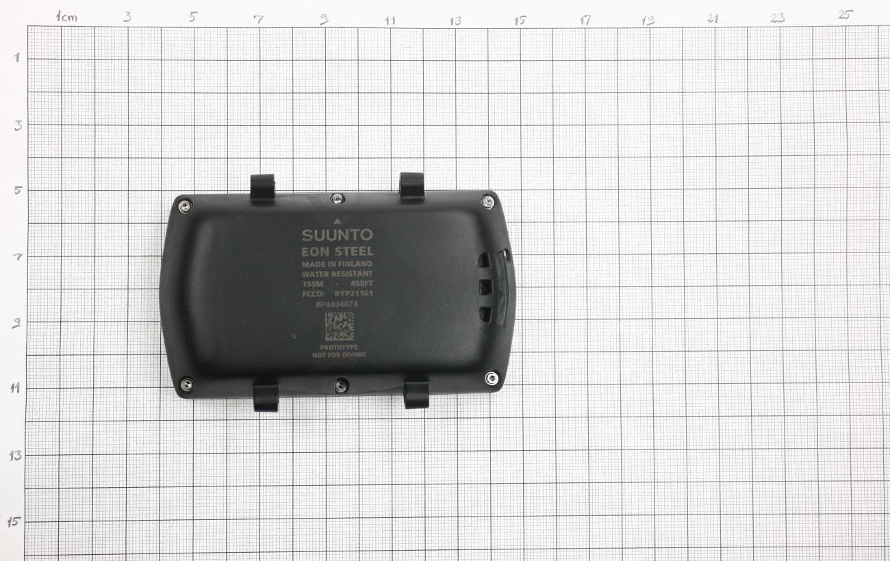
Click to zoom
Application Details
- Equipment Class
- DTS - Digital Transmission System
- Date of Grant
- Jul 06, 2014
- Application Purpose
- Original Equipment
- Date of Application
- Jul 06, 2014
- Equipment Note
- Diving computer with BT4.0 and LF communication ability
- Frequency Range
- 2402.00000000 - 2480.00000000
- Company
- Suunto Oy
- Country
- Finland
Documents & Files
Document Text
Text extracted from the exhibit documents filed with the FCC. Open a document above to read the original.
Users Manual
SUUNTO EON User guide Suunto EON Steel User guide i CONTENTS CONTENTS ......................................................................................................................... I 1 SAFETY .................................................................................................................... 1 1.1 Types of safety precautions .......................................................................... 1 1.2 Safety precautions ......................................................................................... 1 1.3 EU, FCC and IC compliance ......................................................................... 1 2 EON STEEL AT A GLANCE ..................................................................................... 3 2.1 EON Steel overview ....................................................................................... 3 2.2 Accessories .................................................................................................... 3 2.3 Buttons ........................................................................................................... 5 2.4 Icons ............................................................................................................... 5 3 GETTING STARTED ................................................................................................. 6 3.1 Set up EON Steel ............................................................................................ 6 3.2 Calibrating the compass ................................................................................ 6 3.3 Installing scratch guard ................................................................................. 7 3.4 Connect EON Steel to DM5 ............................................................................ 7 4 BASICS ..................................................................................................................... 8 4.1 Main views ...................................................................................................... 8 4.2 Menus ............................................................................................................. 8 4.3 Charge and monitor the battery .................................................................... 9 4.4 Other ............................................................................................................. 10 5 BEFORE DIVING .................................................................................................... 11 5.1 Dive modes ................................................................................................... 11 5.2 Personal and altitude settings for algorithm .............................................. 11 5.3 Gas(es) ......................................................................................................... 12 5.4 Tank pressure .............................................................................................. 13 5.5 User adjustable alarms ................................................................................ 14 6 DURING DIVE ......................................................................................................... 15 6.1 Basic dive data ............................................................................................. 15 6.2 Bookmark ..................................................................................................... 15 6.3 Ascent rate ................................................................................................... 15 6.4 Safety stops and deep stops ....................................................................... 16 6.5 Timer ............................................................................................................. 17 6.6 Alarms, warnings and notifications ............................................................ 17 6.7 Decompression dives .................................................................................. 19 6.8 Oxygen calculations .................................................................................... 21 6.9 Multi-gas diving ............................................................................................ 21 Suunto EON Steel User guide ii 7 AFTER DIVING ....................................................................................................... 23 7.1 Surface & no fly time ................................................................................... 23 7.2 Logbook ........................................................................................................ 23 7.3 Dive history .................................................................................................. 24 8 COMPASS .............................................................................................................. 25 9 DM5 & MOVESCOUNT ........................................................................................... 26 9.1 Downloading logs from EON Steel .............................................................. 26 9.2 Customizing EON Steel ............................................................................... 26 9.3 Updating firmware ........................................................................................ 26 10 SUUNTO FUSED RGBM ......................................................................................... 27 10.1 No decompression time ............................................................................... 27 10.2 Safety stop ................................................................................................... 27 10.3 Deepstop ...................................................................................................... 27 10.4 Decompression ceiling & ascent time ........................................................ 27 10.5 Breaking the ceiling ..................................................................................... 27 11 TAKING …
Text truncated - open the document above for the full version.
Users Manual
SUUNTO EON QUICK GUIDE en 1.Wake up the device by keeping any button pressed. 1. GET STARTED 2.Set up the device. When ready, the device goes to the default Surface mode. 2. CONNECT 1. 4. SET DIVE GAS(ES) 2. 3. SET DIVE SETTINGS 3.After updating and personalizing your device, disconnect it when fully charged. 2.Download and install DM4 software. PARTS (1) Suunto EON (2) Protective boot (3) USB cable (4) Bungee adapter (1) (4) (2) 1.Connect and charge your device. Ensure device is fully charged before first dive. NAVIGATE WITHIN VIEWS ENTER / BACK / EXIT MENU 1. In Menu, select Gases. 2. Select the gas according to your dive plan. Select New gas if your mix is not in the list. NOTE: If a device software update is available, it is dowloaded and installed automatically. BATTERY LIFE 1.Keep middle button pressed to access Menu. 3.When settings are ready, keep middle button pressed to go back and exit. 2.Scroll with upper button and select Dive settings with middle button. WARNING: Download and read complete User Guide before diving www.suunto.com/support 5. PAIR TANK POD 1.Install Tank POD and open tank valve. 3.Wait for green LED on Tank POD to flash. 2.Hold your device close to the Tank POD. PROTO www.movescount.com/dm4www.movescount.com/dm4 2s 2s Menu Gases Active gases Air Menu Dive settings Menu Dive settings 2s 16:30 Mon 20.9. 2s 16:30 Mon 20.9. (3) 35h = max dive time Paired with current active gas Pairing failed Dive settingsDive modes Parameters Dive enablersDevice settingsTank transmitters Set gas * Dive alarms Gases General menu Dive summary Compass Safety stop Set points** Customization About my EON All dives Previous dive * ** [Select gas to edit/remove > add gas] if Multiple gases is enabled. (XX) If CCR is enabled. My dives 19:36 depth, m dive time 0 0’ Surface Mode Dive Mode 48° depth, m dive time 0 0 75’ no deco depth, m dive time 18.2 12’ 48° depth, m dive time 18.2 12’ 19:36 depth, m dive time 0 0’ NOTE: To use advanced features such as multigas or helium, activate enablers through general settings. See User Guide for more details. FCC This device complies with part 15 of the FCC Rules. Operation is subject to the following two conditions: (1) This device may not cause harmful interference, and (2) this device must accept any interference received, including interference that may cause undesired operation. IC: This device complies with Industry Canada licence-exempt RSS standard(s). Operation is subject to the following two conditions: (1) this device may not cause interference, and (2) this device must accept any interference, including interference that may cause undesired operation of the device.
Cover Letter(s)
Request for Confidentiality Date: __26.5..2014______ Subject: Confidentiality Request for: FCC ID:RYP21161 , IC:5175A-21161 Pursuant to FCC 47 CRF 0.457(d) and 0.459 and IC RSP-100, Section 10, the applicant requests that a part of the subject FCC application be held confidential. Type of Confidentiality Requested Exhibit Short Term x Permanent Block Diagrams x Short Term External Photos x Short Term Permanent* 1 Internal Photos Short Term x Permanent Operation Description/Theory of Operation Short Term x Permanent Parts List & Placement/BOM Short Term Permanent Tune-Up Procedure Short Term x Permanent Schematics Short Term Test Setup Photos x Short Term Permanent* User’s Manual *Note: ______(Insert Explanation as Necessary)______ Suunto Oy has spent substantial effort in developing this product and it is one of the first of its kind in industry. Having the subject information easily available to "competition" would negate the advantage they have achieved by developing this product. Not protecting the details of the design will result in financial hardship. Permanent Confidentiality: The applicant requests the exhibits listed above as permanently confidential be permanently withheld from public review due to materials that contain trade secrets and proprietary information not customarily released to the public. Short-Term Confidentiality: The applicant requests the exhibits selected above as short term confidential be withheld from public view for a period of 60 days from the date of the Grant of Equipment Authorization and prior to marketing. This is to avoid premature release of sensitive information prior to marketing or release of the product to the public. Applicant is also aware that they are responsible to notify ACB in the event information regarding the product or the product is made available to the public. ACB will then release the documents listed above for public disclosure pursuant to FCC Public Notice DA 04-1705. NOTE for Industry Canada Applications: The applicant understands that until such time that IC distinguishes between Short Term and Permanent Confidentiality, either type of marked exhibit above will simply be marked Confidential when submitted to IC. Sincerely, By: __________________________ ___Heikki Puuri_____________________ (Signature/Title 2 ) (Print name) 1 - The asterisked items (*) require further justification before permanent confidentiality will be allowed. These also currently require review by the FCC under their Permit-B ut-Ask policy before the grant is issued and can delay completion of an application. Further justification should be added to the note above. One such example for a potted device would be: “The EUT is FULLY potted using a non-removable epoxy based material. Removal of potting material causes irreparable damage to internal circuitry. See photographs exhibits that outline the device before and after potting.” 2 - Must be signed by applicant contact given for applicant on the FCC site, or by the authorized agent if an appropriate authorized agent letter has been provided. Letters should be placed on appropriate letterhead.
External Photos
Photo 1: external, front side Photo 2: external, back side
Internal Photos
Photo 1: internal, back side Photo 2: internal, back side Photo 3: internal, back side Photo 4: internal, back side Photo 5: internal, back side Photo 6: internal, back side
RF Exposure Info
SAR EXCLUSION JUSTIFICATION Manufacturer Suunto Oy Device DW141 FCC ID RYP21161 SAR EXCL USI ON JUSTI FIC ATI ON Guidance document reference: KDB447498 D01 General RF Exposure Guidance v05r02, page 11, paragraph 4.3.1(1). The 1-g and 10-g SAR test exclusion thresholds for 100 MHz to 6 GHz at test separation distances ≤ 50 mm are determined by: [(max. power of channel, including tune-up tolerance, mW) / (min. test separation distance, mm)] * [√f(GHz)] ≤ 3.0 for 1-g SAR and ≤ 7.5 for 10-g extremity SAR, where • f (GHz) is the RF channel transmit frequency in GHz • Power and distance are rounded to the nearest mW and mm before calculation • The result is rounded to one decimal place for comparison • 3.0 and 7.5 are referred to as the numeric thresholds in the step 2 below The test exclusions are applicable only when the minimum test separation distance is ≤ 50 mm and for transmission frequencies between 100 MHz and 6 GHz. When the minimum test separation distance is < 5 mm, a distance of 5 mm according to 5) in section 4.1 is applied to determine SAR test exclusion. These test exclusion conditions are based on source-based time-averaged maximum conducted output power of the RF channel requiring evaluation, adjusted for tune-up tolerance, and the minimum test separation distance required for the exposure conditions. CALC UL ATI ON S AND A SSUM PTI ONS Since the exact distance from the body may vary during use the worst possible distance where the device is in direct contact with the skin will be chosen as test separation distance in calculations. In this condition the antenna is 5 mm away from the body. Actual evaluation: √ CON CLU SIO N The analysis shows that the device qualifies for exemption from SAR testing. Date: JUL 2, 2014
Test Report
Reference number: 274897-6-2 Page 2 of 42 Table of Contents PRODUCT DESCRIPTION 3 Equipment Under Test (EUT) 3 Description of the EUT 3 Ratings and declarations 3 Power Supply 3 Mechanical Size of the EUT 3 Samples 4 GENERAL REMARKS 5 Disclaimer 5 SUMMARY OF TESTING 6 EUT Test Conditions During Testing 6 TEST RESULTS 7 Maximum Peak Conducted Output Power 7 Transmitter Radiated Spurious Emissions 30 – 1000 MHz 10 Transmitter Radiated Spurious Emissions 1 000 – 26 500 MHz 14 Transmitter Band Edge Measurement and Conducted Spurious Emissions 25 6 dB Bandwidth of the Channel 33 Power Spectral Density 36 99% Occupied Bandwidth 39 TEST EQUIPMENT 42 Reference number: 274897-6-2 Page 3 of 42 Product Description PRODUCT DESCRIPTION Equipment Under Test (EUT) Diving computer with BT4.0 and LF communication capability Marketing Name: EON Model: DW141 HW version: - SW version: - FCC ID: RYP21161 IC: 5175A-21161 Description of the EUT The EUT is a diving computer with 123 kHz transceiver radio and Bluetooth 4.0 single mode transceiver radio. This report includes test results for Bluetooth 4.0 tests. EUT is battery operated and has an internal battery. Classification of the device Fixed device Mobile Device (Human body distance > 20cm) Portable Device (Human body distance < 20cm) Modifications Incorporated in the EUT No modifications were applied to the EUT during testing Ratings and declarations Operating Frequency Range (OFR): 2402 – 2480 MHz Channels: 40 Channel separation: 2 MHz Channel bandwidth: 1.186685962 MHz Effective conducted power: 2.94 dBm Transmission technique: Digital Transmission Modulation: GFSK Integral Antenna gain: -2 dBm Power Supply Battery Operated Operating voltage range 3.3 – 4,2VDC Mechanical Size of the EUT Height: 6.0 cm Width:10.5 cm Depth: 2.4 cm Reference number: 274897-6-2 Page 4 of 42 Product Description Samples Two samples were used in the tests. One normal sample with an integral antenna for radiated emissions and one sample with antenna removed and replaced with a coaxial cable with SMA-connector for conducted RF tests. During the tests the EUT was set into continuous transmit and hopping was stopped into the channel under test. Normal test modulation and maximum transmit power was used in all tests. No modifications were done during the tests. Reference number: 274897-6-2 Page 5 of 42 General remarks GENERAL REMARKS Disclaimer This document is issued by the Company under its General Conditions of service accessible at http://www.sgs.com/terms_and_conditions.htm. attention is drawn to the limitation of liability, indemnification and jurisdiction issues defined therein. Any holder of this document is advised that information contained hereon reflects the Company's findings at the time of its intervention only and within the limits of Client's instructions, if any. The Company's sole responsibility is to its Client and this document does not exonerate parties to a transaction from exercising all their rights and obligations under the transaction documents. Any unauthorized alteration, forgery or falsification of the content or appearance of this document is unlawful and offenders may be prosecuted to the fullest extent of the law. Unless otherwise stated the results shown in this test report refer only to the sample(s) tested and such sample(s) are retained for 90 days only. This document cannot be reproduced except in full, without prior approval of the Company. Reference number: 274897-6-2 Page 6 of 42 Summary of Testing SUMMARY OF TESTING Test Specification Description of Test Result §15.247(b)(3) / RSS-210 A8.4 Maximum Peak Conducted Output Power PASS §15.247(a)(2) / RSS-210 A8.2 6 dB Bandwidth PASS §15.247(e) / RSS-210 A8.2 Power Spectral Density PASS RSS-GEN 4.6.1 99% Occupied Bandwidth PASS §15.247(d) / RSS-210 A8.5 100 kHz Bandwidth of Frequency Band Edges and Conducted Spurious Emissions PASS §15.209(a), §15.247(d) / RSS-210 A8.5 Radiated Emissions Within The Restricted Bands PASS §15.109 / RSS-GEN 7.2.3.2 Unintentional Radiated Emissions PASS EUT Test Conditions During Testing The EUT was in continuous transmit mode during all the tests. The hopping was stopped and the EUT was configured into the wanted channel. Normal modulation and duty cycle was applied in all the tests. Duty cycle of the EUT was measured and it was 96.2% which is the highest possible duty cycle that the EUT is capable of. The tests were performed with the EUT being in three different orthogonal positions: X, Y, Z. Following channels were used during the tests when the hopping was stopped: Channel Low (Ch 0) = 2402 MHz Channel Mid (Ch 20) = 2440 MHz Channel High (Ch 39) = 2480 MHz Test Facility Testing Location / address: FCC registration number: 90598 SGS Fimko Ltd Särkiniementie 3 FI-00210, HELSINKI FINLAND Testing Location / address: FCC registration number: 178986 Industry Canada registration number: 8708A-2 SGS Fimko Ltd Karakaarenkuja 4 FI-02610, ESPOO FINLAND Reference number: 274897-6-2 Page 7 of 42 Conducted Output Power Test TEST RESULTS Maximum Peak Conducted Output Power Standard: ANSI C63.10 (2009) Tested by: NKO Date: 28.5.2014 Humidity: 27% Temperature: 25.3 °C Measurement uncertainty ± 2,87dB Level of confidence 95 % (k = 2) FCC Rule: 15.247(b)(3) For systems using digital modulation in the 2400-2483.5 MHz bands the limit is 1 Watt. As an alternative to a peak power measurement, compliance with the one Watt limit can be based on a measurement of the maximum conducted output power. Results: Channel Conducted Power [dBm] Limit [dBm] Margin [dBm] Result Low 2.82 30 27.18 PASS Mid 2.94 30 27.06 PASS High 2.85 30 27.15 PASS Reference number: 274897-6-2 Page 8 of 42 Conducted Output Power Test Date: 28.MAY.2014 15:30:09 Figure 1. Channel Low. Date: 28.MAY.2014 15:31:43 Reference number: 274897-6-2 Page 9 of 42 Conducted Output Power Test Figure 2. Channel Mid. Date: 28.MAY.2014 15:32:42 Figure 3. Channel High. Reference number: 274897-6-2 Page 10 of 42 Radiated Spurious Emissio…
Text truncated - open the document above for the full version.
Contact Information
Applicant
Michael Vilen(Compliance Manager)
Technical Contact
Test Firm
SGS Fimko LtdJari Merikari
Technical Specifications
| # | Rule Parts | Frequency Range | Power Output |
|---|---|---|---|
| 1 | 15C | 2.40 GHz - 2.48 GHz | 2.00 mW |
Other Applications from Suunto Oy
RYPOW245
Apr 27, 2026Outdoor Watch
Equipment Class
DTS - Digital Transmission SystemRYPHS252
Dec 08, 2025Headphones
Equipment Class
DTS - Digital Transmission System
RYPOW222
Apr 23, 2023Sports Watch with GNSS and BLE and WLAN Connectivity
Equipment Class
JAB - Part 15 Class B Digital Device
RYP2609
Mar 04, 2021Sports watch with GPS and BLE Connectivity
Equipment Class
JAB - Part 15 Class B Digital Device
RYP2540
Jan 06, 2020SUUNTO 7
Equipment Class
DTS - Digital Transmission System