RYP25002DHEART RATE TRANSMITTER
Suunto Oy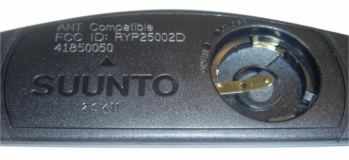
Click to zoom
Application Details
- Equipment Class
- DXX - Part 15 Low Power Communication Device Transmitter
- Date of Grant
- Jun 30, 2004
- Application Purpose
- Original Equipment
- Date of Application
- May 18, 2004
- Equipment Note
- HEART RATE TRANSMITTER
- Frequency Range
- 2465.00000000 - 2465.00000000
- Company
- Suunto Oy
- Country
- Finland
Documents & Files
Document Text
Text extracted from the exhibit documents filed with the FCC. Open a document above to read the original.
Users Manual
4 1. GENERAL INFORMATION Suunto t6 is your personal tool for better performance in sports. It measures the time between your heartbeats with the accuracy of milliseconds and records it for deeper analysis. The Suunto Training Manager PC software uses the heart rate variation data to analyze the effect of your training and to calculate several other body parameters. Relating this information with your current fitness level, the software also indicates the scale of training load that you need for different training effects. For the first time, in field conditions Suunto t6 tells you whether your training really improves your condition and helps you adjust your training programs accordingly. When you set the target effect for your training, you can use the software to calculate the time and heart rate to reach it. During a training session, Suunto t6 helps you reach the target by offering several control functions such as heart rate limits, real time average heart rate, and a customizable display of stopwatch, lap time, interval timer and altitude. Together with versatile timing, altimeter and logbook functions this makes Suunto t6 a perfect performance monitor for all kinds of sports at all performance levels. Suunto t6 can be upgraded with different wireless accessories such as speed and distance sensors for running and cycling. NOTE: Read this Instruction manual carefully and make sure you understand the use, displays and limitations of this instrument before using the device. Also read the guidebook ‘How not to rely on luck when optimizing the training effect’ to learn how to get the best benefits out of using the Suunto t6. You find the guidebook on the CD delivered with the Suunto t6. 5 1.1. CHECKLIST Make sure the package contains the following items: • Suunto t6 • Transmitter belt (Suunto ANT-transmission compatible) • PC-interface cable • CD containing the Suunto Training Manager, t6 User Manuals and Training Guide Book • Suunto t6 User Manual • Suunto t6 Pocket Guide Should any of these be missing from the package, contact the representative who sold you the package. 6 1.2. SUUNTO T6 FEATURES The Suunto t6 has the following features. Time mode • Time, calendar, alarm, adjustment of units and general settings Alti/Baro mode • Altitude, vertical speed, cumulative ascent and descent • Temperature, air pressure, weather memory Training mode • Heart rate, stopwatch with split times, interval timer, logbook and other training control functions SPD/DST mode (available only when the wrist unit is paired with an external speed and distance sensor) • Speed, distance, automatic lap time by distance, interval training by distance, speed limit alarm PC-Software • Upload and store the logs on your PC • Follow up the training effect and several physiological parameters based on the recorded heart rate interval data • Create training plans and monitor your progress SuuntoSports.com • Upload your logs and publish them on the Web • Share and compare your training experiences with others • Download training plans published by other users 7 1.3. CARE AND MAINTENANCE Only perform the procedures described in this manual. Never attempt to disassemble or service your Suunto t6. Protect your Suunto t6 from shocks, extreme heat and prolonged exposure to direct sunlight. If not in use, store your Suunto t6 in a clean and dry environment at room temperature. Your Suunto t6 can be wiped clean with a lightly moistened (warm water) cloth. If there are stubborn stains or marks, you can apply mild soap to the area. Do not expose your Suunto t6 to strong chemicals such as gasoline, cleaning solvents, acetone, alcohol, insect repellents, adhesives and paint, as they will damage the unit’s seals, case and finish. Keep the area around the sensor free of dirt and sand. Never insert any objects into the sensor opening. 1.4. WATER RESISTANCE Your Suunto t6 is water resistant up to 100 m/330 ft. and the transmitter belt to 20m/ 66ft. according to ISO 2281 standard (www.iso.ch). This means that you can use Suunto t6 for swimming and other water sports activities but it should not be used for scuba diving or freediving. To maintain water resistance and to ensure that the warranty remains valid, it is strongly recommended to have all service, except for battery change, to be done by authorized Suunto service personnel. NOTE: Do not push the buttons while swimming or in contact with water under any circumstances. Deliberate or unintentional pressing of the buttons while the unit is submerged could cause the unit to malfunction. NOTE: Despite the fact that both the Suunto t6 and the transmitter belt are water resistant, the radio signal does not carry in water making communication between Suunto t6 and the transmitter belt impossible. 8 1.5. REPLACING THE BATTERY Your Suunto t6 operates on a 3-Volt lithium cell, type: CR 2032. The life expectancy is approximately 12 months in the Time mode or 300 hours of heart rate transmission in ideal operating temperatures. The low-battery warning indicator is activated on the display when approximately 5–15 percent of the battery capacity is still available. When this occurs, you should replace the battery. However, extremely cold weather may activate the low battery warning indicator, even though the battery is still fully operational. If the battery warning indicator is activated in temperatures above 10°C (50°F), replace the battery. NOTE: When the low-battery indicator is on, the HR transmission becomes automati- cally disabled. To replace the battery: 1. Insert a coin into the slot located on the battery compartment cover on the backside of Suunto t6. 2. Turn the coin counterclockwise until it is aligned with the open position marker. 9 3. Remove the battery compartment cover. Ensure that the O ring and all surfaces are clean and dry. Do not stretch the O ring. 4. Remove the old battery carefully. 5. Place the new battery into the battery compartment with the positive side facing up…
Text truncated - open the document above for the full version.
Cover Letter(s)
NEMKO OY, P.O.BOX 19 (PERKKAANTIE 11), 02601 ESPOO, TEL. +358 424 54541, FAX +358 9 5489 6371, Y 1706698-9 May 17, 2004 Federal Communications Comission Authorization and Standards Division 7435 Oakland Mills Rd. Columbia, MD 2046 Re: FCC ID: RYP25002D Gentlemen: Nemko Oy (former Nemko Product Services Oy) has tested this Intentional Radiator in accordance with the requirements contained in the Part 15 of Title 47 CFR. To the best of my knowledge, these tests were performed using the criteria established in ANSI C63.4, 2001 and demonstrates that the equipment complies with the published standard. The Open Area Test Site (Semi-anechoic chamber, Reg. No. 91087) used for these measurements is located at Perkkaantie 11, ESPOO, FINLAND. Site information required by Public Notice 24541 in accordance with ANSI C63.4-2001 was filed with the FCC Authorization and Evaluation Division Sampling and Measurements Branch in June 1998 and renewed in August 2001. Sincerely,
External Photos
R6 (100500) HR Transmitter Internal Photos Revision A.2 Document n. 200001302 2004-05-07 R6 (100500) Document number: 200001302, rev. A.2 HR Transmitter Internal Photos OlOj 2004-05-07 1(2) 1 HEART RATE TRANSMITTER INTERNAL PHOTOS 1.1 Front 1.2 Back 1.3 Back cover with battery cover removed R6 (100500) Document number: 200001302, rev. A.2 HR Transmitter Internal Photos OlOj 2004-05-07 2(2) 1.4 Back cover removed 1.5 PCB removed
ID Label/Location Info
R6 (100500) HR Transmitter ID Label Revision A.1 Document n. 200001298 2004-05-04 R6 (100500) Document number: 200001298, rev. A.1 HR Transmitter ID Label OlOj 2004-05-04 1(1) 1 HEART RATE TRANSMITTER ID LABEL 1.1 ID Label Marking ID label is laser marked to the back cover of the heart rate transmitter. Back cover is plastic with laser sensitive pigment in it. Marking is permanent and it does not wear off. 1.2 Photo of ID Label
Internal Photos
R6 (100500) HR Transmitter Internal Photos Revision A.2 Document n. 200001302 2004-05-07 R6 (100500) Document number: 200001302, rev. A.2 HR Transmitter Internal Photos OlOj 2004-05-07 1(2) 1 HEART RATE TRANSMITTER INTERNAL PHOTOS 1.1 Front 1.2 Back 1.3 Back cover with battery cover removed R6 (100500) Document number: 200001302, rev. A.2 HR Transmitter Internal Photos OlOj 2004-05-07 2(2) 1.4 Back cover removed 1.5 PCB removed
Test Report
Type: Suunto 2SKU Test report: 1032187 Page 2 (14) Date 30.04.2004 Summary of performed tests and test results Section in CFR 47 Result 15.249 (a) Field Strength of Fundamental PASS 15.249 (a) Field Strength of Spurious Emissions PASS Explanations: PASS The EUT passed that particular test. FAIL The EUT failed that particular test. Type: Suunto 2SKU Test report: 1032187 Page 3 (14) Date 30.04.2004 Contents Summary of performed tests and test results .......................................................................................... 2 1. EUT and Accessory Information ......................................................................................................... 4 1.1 EUT description ........................................................................................................................ 4 1.2 EUT and accessories ............................................................................................................... 4 2. Standards and measurement methods ..............................................................................................5 3. Test results ......................................................................................................................................... 5 3.1 Field Strength of Fundamental ................................................................................................. 5 3.1.1 Test method and limit ............................................................................................................... 5 3.1.2 EUT operation mode ................................................................................................................ 5 3.1.3 Test data................................................................................................................................... 6 3.1.4 EUT test setup.......................................................................................................................... 6 3.1.5 Result ....................................................................................................................................... 7 3.2 Field Strength of Spurious Emissions ...................................................................................... 8 3.2.1 Test method and limit ............................................................................................................... 8 3.2.2 EUT operation mode ................................................................................................................ 9 3.2.3 Test data................................................................................................................................... 9 3.2.4 EUT test setup.......................................................................................................................... 9 3.2.5 Spurious emissions results....................................................................................................10 4. List of test equipment........................................................................................................................ 14 Type: Suunto 2SKU Test report: 1032187 Page 4 (14) Date 30.04.2004 1. EUT and Accessory Information 1.1 EUT description EUT is the transmitter of the heart rate monitoring system. The highest internal frequency of the EUT was 2465 MHz. For the facilitation of the spurious emissions tests (for finding of maximum value) the customer delivered also the sample, which transmitted continuously, because duty cycle of the production model is only 0.001 (200 μs transmission every 200 ms). Therefore measuring results are peak values. Average level ≤ Peak level – 20 log (duty cycle). (Duty cycle = (200 ms + 200 μs) / 200 μs = 60 dB). Average level ≤ Peak level – 60 dB. 1.2 EUT and accessories unit type S/N EUT Transmitter of the heart rate monitoring system Suunto 2SKU - Power SupplyLi-Mn Battery 3 V Varta CR 2032 Type: Suunto 2SKU Test report: 1032187 Page 5 (14) Date 30.04.2004 2. Standards and measurement methods The test were performed in guidance of the CFR 47 Part 15, Subpart B, Class B, ANSI C63.4 (2001) and EN 55022. 3. Test results 3.1 Field Strength of Fundamental The test was performed as a compliance test. The test parameters concerned were as follows: Site name Nemko Oy / Perkkaa Date of testing 13.04.2004 Test equipment 350, 42, 82, 184, 403 Test conditions 22.3 °C, 32.5 % RH Test result PASS 3.1.1 Test method and limit Vertical and horizontal polarizations in the frequency 2465 MHz was measured by using the peak detector. During the measurement the turntable was rotated from 0° to 360° and the antenna was raised from 1.0 m and 4.0 m. Limit 15.249 (a) Fundamental Frequency Field Strength of Fundamental MHz (millivolts/meter) dBμV/m 2465.0 50 94 3.1.2 EUT operation mode EUT operation mode TX ON EUT operation voltage 3 VDC Type: Suunto 2SKU Test report: 1032187 Page 6 (14) Date 30.04.2004 3.1.3 Test data The measurement results were obtained as described below. (measurement distance: 3 m) E [μV/m] = U RX + A CABLE + AF - G PREAMP Where U RX receiver reading A CABLE attenuation of the cable AF antenna factor G PREAMP gain of the preamplifier 3.1.4 EUT test setup Photograph 1. Radiated emissions test setup Type: Suunto 2SKU Test report: 1032187 Page 7 (14) Date 30.04.2004 Photograph 2. Radiated emissions test setup 3.1.5 Result Frequency Level (PK) Horizontal/ Level (PK) Vertical Limit Remarks MHz mV/m mV/m mV/m 2465.0 29.7 27.7 50.00 Type: Suunto 2SKU Test report: 1032187 Page 8 (14) Date 30.04.2004 3.2 Field Strength of Spurious Emissions Site name Nemko Oy / Perkkaa Date of testing 22.04.2004 Test equipment 350, 338, 42, 543, 544, K1, 319, 525, 83, 84, 85, 86, 87, 88, 508, 184, 403 Test conditions 23.1 °C. 35.0 % RH Test result PASS 3.2.1 Test method and limit The test was performed in a semi-anechoic shielded room. The EUT was placed on a non-conductive 0.8 m high table standing on the turntable (photograph 1). During the test in the fre…
Text truncated - open the document above for the full version.
Test Setup Photos
Type: Suunto 2SKU Test report: 1032187 Page 2 (14) Date 30.04.2004 Summary of performed tests and test results Section in CFR 47 Result 15.249 (a) Field Strength of Fundamental PASS 15.249 (a) Field Strength of Spurious Emissions PASS Explanations: PASS The EUT passed that particular test. FAIL The EUT failed that particular test. Type: Suunto 2SKU Test report: 1032187 Page 3 (14) Date 30.04.2004 Contents Summary of performed tests and test results .......................................................................................... 2 1. EUT and Accessory Information ......................................................................................................... 4 1.1 EUT description ........................................................................................................................ 4 1.2 EUT and accessories ............................................................................................................... 4 2. Standards and measurement methods ..............................................................................................5 3. Test results ......................................................................................................................................... 5 3.1 Field Strength of Fundamental ................................................................................................. 5 3.1.1 Test method and limit ............................................................................................................... 5 3.1.2 EUT operation mode ................................................................................................................ 5 3.1.3 Test data................................................................................................................................... 6 3.1.4 EUT test setup.......................................................................................................................... 6 3.1.5 Result ....................................................................................................................................... 7 3.2 Field Strength of Spurious Emissions ...................................................................................... 8 3.2.1 Test method and limit ............................................................................................................... 8 3.2.2 EUT operation mode ................................................................................................................ 9 3.2.3 Test data................................................................................................................................... 9 3.2.4 EUT test setup.......................................................................................................................... 9 3.2.5 Spurious emissions results....................................................................................................10 4. List of test equipment........................................................................................................................ 14 Type: Suunto 2SKU Test report: 1032187 Page 4 (14) Date 30.04.2004 1. EUT and Accessory Information 1.1 EUT description EUT is the transmitter of the heart rate monitoring system. The highest internal frequency of the EUT was 2465 MHz. For the facilitation of the spurious emissions tests (for finding of maximum value) the customer delivered also the sample, which transmitted continuously, because duty cycle of the production model is only 0.001 (200 μs transmission every 200 ms). Therefore measuring results are peak values. Average level ≤ Peak level – 20 log (duty cycle). (Duty cycle = (200 ms + 200 μs) / 200 μs = 60 dB). Average level ≤ Peak level – 60 dB. 1.2 EUT and accessories unit type S/N EUT Transmitter of the heart rate monitoring system Suunto 2SKU - Power SupplyLi-Mn Battery 3 V Varta CR 2032 Type: Suunto 2SKU Test report: 1032187 Page 5 (14) Date 30.04.2004 2. Standards and measurement methods The test were performed in guidance of the CFR 47 Part 15, Subpart B, Class B, ANSI C63.4 (2001) and EN 55022. 3. Test results 3.1 Field Strength of Fundamental The test was performed as a compliance test. The test parameters concerned were as follows: Site name Nemko Oy / Perkkaa Date of testing 13.04.2004 Test equipment 350, 42, 82, 184, 403 Test conditions 22.3 °C, 32.5 % RH Test result PASS 3.1.1 Test method and limit Vertical and horizontal polarizations in the frequency 2465 MHz was measured by using the peak detector. During the measurement the turntable was rotated from 0° to 360° and the antenna was raised from 1.0 m and 4.0 m. Limit 15.249 (a) Fundamental Frequency Field Strength of Fundamental MHz (millivolts/meter) dBμV/m 2465.0 50 94 3.1.2 EUT operation mode EUT operation mode TX ON EUT operation voltage 3 VDC Type: Suunto 2SKU Test report: 1032187 Page 6 (14) Date 30.04.2004 3.1.3 Test data The measurement results were obtained as described below. (measurement distance: 3 m) E [μV/m] = U RX + A CABLE + AF - G PREAMP Where U RX receiver reading A CABLE attenuation of the cable AF antenna factor G PREAMP gain of the preamplifier 3.1.4 EUT test setup Photograph 1. Radiated emissions test setup Type: Suunto 2SKU Test report: 1032187 Page 7 (14) Date 30.04.2004 Photograph 2. Radiated emissions test setup 3.1.5 Result Frequency Level (PK) Horizontal/ Level (PK) Vertical Limit Remarks MHz mV/m mV/m mV/m 2465.0 29.7 27.7 50.00 Type: Suunto 2SKU Test report: 1032187 Page 8 (14) Date 30.04.2004 3.2 Field Strength of Spurious Emissions Site name Nemko Oy / Perkkaa Date of testing 22.04.2004 Test equipment 350, 338, 42, 543, 544, K1, 319, 525, 83, 84, 85, 86, 87, 88, 508, 184, 403 Test conditions 23.1 °C. 35.0 % RH Test result PASS 3.2.1 Test method and limit The test was performed in a semi-anechoic shielded room. The EUT was placed on a non-conductive 0.8 m high table standing on the turntable (photograph 1). During the test in the fre…
Text truncated - open the document above for the full version.
Contact Information
Applicant
Michael Vilen(Compliance Manager)
Test Firm
Nemko Product Services OyJanne Nyman
Technical Specifications
| # | Rule Parts | Frequency Range | Power Output |
|---|---|---|---|
| 1 | 15C | 2.46 GHz - 2.46 GHz | - |
Other Applications from Suunto Oy
RYPOW245
Apr 27, 2026Outdoor Watch
Equipment Class
DTS - Digital Transmission SystemRYPHS252
Dec 08, 2025Headphones
Equipment Class
DTS - Digital Transmission System
RYPOW222
Apr 23, 2023Sports Watch with GNSS and BLE and WLAN Connectivity
Equipment Class
JAB - Part 15 Class B Digital Device
RYP2609
Mar 04, 2021Sports watch with GPS and BLE Connectivity
Equipment Class
JAB - Part 15 Class B Digital Device
RYP2540
Jan 06, 2020SUUNTO 7
Equipment Class
DTS - Digital Transmission System