RYSD62EFCAMWireless CCD Camera
Luxeon Corp.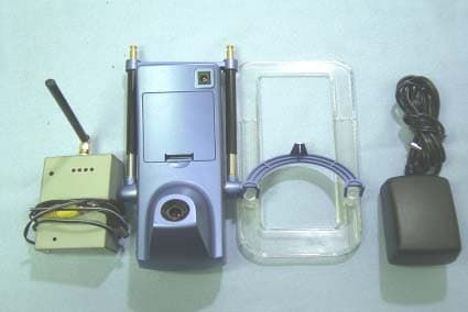
Click to zoom
Application Details
- Equipment Class
- DXT - Part 15 Low Power Transceiver, Rx Verified
- Date of Grant
- Jul 15, 2004
- Application Purpose
- Original Equipment
- Date of Application
- Jul 15, 2004
- Equipment Note
- Wireless CCD Camera
- Frequency Range
- 2414.00000000 - 2468.00000000
- Company
- Luxeon Corp.
- Country
- Taiwan
Documents & Files
Document Text
Text extracted from the exhibit documents filed with the FCC. Open a document above to read the original.
Users Manual
D620EF-CAM Wireless Camera Set User’s Guide Page 1 D620EF-CAM Wireless Camera Set for the D620EF projector User’s Guide D620EF-CAM Wireless Camera Set User’s Guide Page 2 Table of Contents Getting Started 3 FCC Notice 3 Product Features 4 Applications 4 Identify the Controls 5-6 Using the Wireless Camera 6 Setting up the wireless camera 6 Powering On the wireless camera 7 Powering Off the wireless camera 7 Switching frequency channels 7 Recharging the batteries 7 Adjusting the Captured Image 8 Adjusting the Wireless Camera height 8 Adjusting the Camera Focus 8 Care and Maintenance 9 Protecting the wireless camera 9 Cleaning the lens 9 FAQ & Troubleshooting 10-12 Specifications 13 Wireless Camera 13 Wireless Receiver 13 D620EF-CAM Wireless Camera Set User’s Guide Page 3 Getting Started Federal Communications Commission (FCC) Notice This equipment has been tested and found to comply with the limits for a Class A digital device, pursuant to Part 15 of the FCC Rules. These limits are designed to provide reasonable protection against harmful interference when the equipment is operated in a residential installation. This equipment generates, use, and can radiate radio frequency energy and if not installed and used in accordance with the instruction manual may cause harmful interference to radio communications. However, there is no guarantee that interference will not occur in a particular installation. If this equipment does cause harmful interference to radio or television reception, which can be determined by turning the equipment off and on, the user is encouraged to try to correct the interference by one or more of the following measures: z Reorient or relocate the receiving antenna. z Increase the separation between the equipment and receiver. z Connect the equipment into an outlet on a circuit different from that to which the receiver is connected. z Consult the dealer or an experienced radio/TV technician for help. Notice: Any unauthorized change or modification that is not expressly approved by the partly responsible for compliance could void the user's authority to operate the equipment. D620EF-CAM Wireless Camera Set User’s Guide Page 4 Product Features Get ready for high-quality “wireless” projection of real-object images. The D620EF-CAM wireless camera set can transmit real-time images from any corners of the home, the classroom, the meeting room, and the office to the D620EF projector. With the D620EF projector & the D620EF-CAM as an integrated solution, you will have a revolutionary projection system to project live images of any objects onto the projected screen with hassle-free setup. The D620EF-CAM wireless camera set offers the latest in real-time image capture & transfer technology, including: A complete replacement for your document camera when operated with the D620EF projector High-quality image via Sony’s high-performance HAD CCD technology Reliable 2.4GHz RF wireless technology for consistent transmission within 30 meters 16.7 million displayable colors Can be equipped with rechargeable batteries for easy movements 4 wireless channels available for switching to avoid signal interferences Can capture images of documents, people, and any other objects High performance focus lens Compact size Applications Replacement for the common document cameras Replacement for expensive digital projectors with document cameras Deliver versatile presentations in which you can capture real-time images of any real-object from anywhere including data on your computer screen Make possible the real-time projection of facial images of the presenters and other participants in a meeting Easily share the projector between presenters without the fuss of plugging & unplugging the data cable Can broadcast outdoor activities to the projector indoors D620EF-CAM Wireless Camera Set User’s Guide Page 5 Identify the Product Controls The Wireless Camera Symbol Control Function 1 Power on/off Button This button powers on and off the wireless camera 2 Channel Switch This switch enables you to switch to different frequency channels. 3 Extendable slider Extends the wireless camera to a height that allows it to view documents in an upright position. 4 Focus adjustment This adjustment ring controls the focus on the image. 5. DC power inlet The adapter plugs in here to charge the batteries and provide power to the camera. 6 Elevation platform 7 Battery Compartment D620EF-CAM Wireless Camera Set User’s Guide Page 6 The Wireless Receiver (mounted to the D620EF projector) Symbol Control Function 1 Channel select button This select button enables you to switch to different frequency channels. 2 Channel LEDs When selecting a certain channel, its corresponding LED will light on. Using the Wireless Camera set Setting up the Wireless Camera set Connect the Receiver module to the Projector 1. Attach the Receiver module to the two joints protruding from the D620PW projector. 2. Connect one end of the DC power cable to the D620PW projector’s “Screen Control” port. Connect the other end of the DC power cable to the Receiver’s “DC” port. 3. Connect one end of the RCA video cable to the D620PW projector’s “Video” port. Connect the other end of the RCA video cable to the Receiver’s “Video” port. Load the batteries into the Wireless Camera 1. Open the hatch at the lower part of the wireless camera to reveal the battery storage area. 2. Load 8 rechargeable Ni-MH AA batteries into the battery storage area. 3. Close the hatch. *DO NOT USE BATTERIES OTHER THAN AA RECHARGEABLE NI-MH (NICKEL METAL HYDRIDE) BATTERIES. D620EF-CAM Wireless Camera Set User’s Guide Page 7 Powering On the Wireless Camera set 1. Make sure the 8 batteries are loaded correctly into the wireless camera. If you have no batteries loaded, then please make sure the AC adapter is connected to the DC port of the wireless camera, and the adapter is plugged to an AC power outlet. 2. Press the power on/off button on the top left side of t…
Text truncated - open the document above for the full version.
Cover Letter(s)
Mike Kuo From: [email protected] Sent: July13 2004 Tuesday 7:22 PM To: Mike Kuo Cc: CCS-Taiwan, Wklo (E-mail); [email protected]; [email protected]; [email protected] Subject: Luxeon Corp., FCC ID: RYSD620PWCAM, Assessment NO.: AN04T3973 7/16/2004 Hi Mike, Please refer to the following for our replies. Thank you for your advice. Best regards, Ting Question #1: Based upon antenna specification, the antenna connector is SMA ( male ) connector which is considered as standard antenna connector and does not comply with Section 15.203 of FCC rules. Please address this non-compliance issue. Ans #1: An R-SMA connector is adopted. Please refer to the attached for the revised antanna specs. Question #2: Based upon technical specification in the user manual, this device can be turned to four channel, range from 2414 - 2468MHz. However, this fundamental frequency range does not agree with the frequency range listed in the test report ( 2410 - 2472 MHz). Please explain. Ans # 2: Page 13 of the user manual has been revised. Please refer to it. Question #3: The EUT description listed in the test report is misleading. The transmitter used by this device is not considered as Wireless Local Area Network . Please make necessary correction. Ans #3: The test report has been revised. Please refer to it. Question #4: Section 2 of test report, please update the frequency range to the actual operating frequency range. Do not list frequency band. Ans #4: The actual operating frequency range is updated in Page 4. Please refer to the following revised test report. Question #5: Proposed FCC ID label includes FCC DoC. Please explain why this device is also subject to FCC DoC procedures. Ans #5: The FCC DoC logo is removed. Please refer to the following revised label format. Best Regards Mike Kuo Mike Kuo <[email protected]> 2004/06/17 01:37 AM "CCS-Taiwan, Ting (E-mail)" <[email protected]>, "CCS-Taiwan, Wklo (E-mail)" <[email protected]> The items indicated above must be submitted before processing can continue on the above referenced application. Failure to provide the requested information within 30 days of the original e-mail date may result in application dismissal and forfeiture of the filing fee. Also, please note that partial responses increase processing time and should not be submitted. Any questions about the content of this correspondence should be directed to the e-mail address listed below the name of the sender. 7/16/2004
External Photos
Compliance Certification Services Inc. Report No: B31219601 Date of Issue: April 20, 2004 Page 1 of 11 EXTERNAL PHOTO Compliance Certification Services Inc. Report No: B31219601 Date of Issue: April 20, 2004 Page 2 Compliance Certification Services Inc. Report No: B31219601 Date of Issue: April 20, 2004 Page 3
Internal Photos
Compliance Certification Services Inc. Report No: B31219601 Date of Issue: April 20, 2004 Page 4 INTERNAL PHOTO Compliance Certification Services Inc. Report No: B31219601 Date of Issue: April 20, 2004 Page 5 Compliance Certification Services Inc. Report No: B31219601 Date of Issue: April 20, 2004 Page 6 Compliance Certification Services Inc. Report No: B31219601 Date of Issue: April 20, 2004 Page 7 Compliance Certification Services Inc. Report No: B31219601 Date of Issue: April 20, 2004 Page 8 Compliance Certification Services Inc. Report No: B31219601 Date of Issue: April 20, 2004 Page 9 Compliance Certification Services Inc. Report No: B31219601 Date of Issue: April 20, 2004 Page 10 Compliance Certification Services Inc. Report No: B31219601 Date of Issue: April 20, 2004 Page 11
Parts List/Tune Up Info
2.4GHz ISM Band ARFA Standard Antenna Technical Data Electrical Properties Frequency Range2.4~2.5GHz Impedance50 Ohms nominal VSWR<=2.0 Gain2.8dBi RadiationOmni PolarizationVertical Electrical Wave1/4λ Dipole (Elevated Feed) Standard Connector BaseBrass with Black Chrome Plate Operation Temperature -20°C ~ +65°C Store Temperature-30°C ~ +75°C Unit: mm Unit: mm
Test Report
Compliance Certification Services Inc. Report No: B31219601-RP FCC ID: RYSD620EFCAM Date of Issue: April 20, 2004 Note: This report shall not be reproduced except in full, without the written approval of Compliance Certification Services Inc. This document may be altered or revised by Compliance Certification Services Inc. personnel only, and shall be noted in the revision section of the document. Page 1 of 31 FCC 47 CFR PART 15 SUBPART C TEST REPORT For LUXEON Corp. CCD Camera with 2.4GHz RF Wireless transmitter Model: D620EF-CAM Trade Name: LUXEON Prepared for LUXEON Corp. 8F-1, No. 10, Lane 360, Sec. 1, Neihu Rd., Neihu Dist, Taipei, Taiwan Prepared by Compliance Certification Services Inc. No. 81-1, Lane 210, Bade Rd. 2, Luchu Hsiang, Taoyuan Hsien, (338) Taiwan, R.O.C. TEL: 886-3-324-0332 FAX: 886-3-324-5235 Compliance Certification Services Inc. Report No: B31219601-RP FCC ID: RYSD620EFCAM Date of Issue: April 20, 2004 Page 2 TABLE OF CONTENTS 1. TEST RESULT CERTIFICATION............................................................................................. 3 2. EUT DESCRIPTION .................................................................................................................... 4 3. TEST METHODOLOGY ............................................................................................................. 5 3.1 EUT CONFIGURATION...................................................................................................................5 3.2 EUT EXERCISE...............................................................................................................................5 3.3 GENERAL TEST PROCEDURES........................................................................................................5 3.4 FCC PART 15.205 RESTRICTED BANDS OF OPERATIONS ...................................................6 3.5 DESCRIPTION OF TEST MODES......................................................................................................6 4. INSTRUMENT CALIBRATION................................................................................................. 7 5. FACILITIES AND ACCREDITATIONS ................................................................................... 8 5.1 FACILITIES ....................................................................................................................................8 5.2 EQUIPMENT...................................................................................................................................8 5.3 LABORATORY ACCREDITATIONS AND LISTING.............................................................................8 5.4 TABLE OF ACCREDITATIONS AND LISTINGS..................................................................................9 6. SETUP OF EQUIPMENT UNDER TEST ................................................................................ 10 6.1 SETUP CONFIGURATION OF EUT..................................................................................................10 6.2 SUPPORT EQUIPMENT ..........................................................................................................10 7. FCC PART 15.249 REQUIREMENTS...................................................................................... 11 7.1 BAND EDGES MEASUREMENT ...........................................................................................11 7.2 SPURIOUS EMISSION ............................................................................................................17 7.3 POWERLINE CONDUCTED EMISSIONS.............................................................................26 Compliance Certification Services Inc. Report No: B31219601-RP FCC ID: RYSD620EFCAM Date of Issue: April 20, 2004 Page 4 2. EUT DESCRIPTION Product CCD Camera with 2.4GHz RF Wireless transmitter Trade Name IOGEAR Model Number D620EF-CAM Model Discrepancy N/A Power Supply Transmitter: Powered by an AC/DC power adapter Model Number: WDD-131DBC I/P: AC 100-230V, 50/60Hz, 0.5A O/P: DC 12V, 2.0A or by 4 x AA Batteries Receive: Powered by projector Frequency Range 4 channels (2414,2432,2450,2468MHz) Modulation Technique FM Antenna Gain Monopole Antenna / Gain: 2.8 dBi (max) Temperature Range Transmitter: 0°C ~ +50°C Receive: 0°C ~ +60°C Note: This submittal(s) (test report) is intended for FCC ID: RYSD620EFCAM filing to comply with Section 15.207, 15.209 and 15.249 of the FCC Part 15, Subpart C Rules. Compliance Certification Services Inc. Report No: B31219601-RP FCC ID: RYSD620EFCAM Date of Issue: April 20, 2004 Page 5 3. TEST METHODOLOGY The tests documented in this report were performed in accordance with ANSI C63.4 and FCC CFR 47 2.1046, 2.1047, 2.1049, 2.1051, 2.1053, 2.1055, 2.1057, 15.207, 15.209 and 15.249. 3.1 EUT CONFIGURATION The EUT configuration for testing is installed on RF field strength measurement to meet the Commissions requirement and operating in a manner that intends to maximize its emission characteristics in a continuous normal application. 3.2 EUT EXERCISE The EUT was operated in the engineering mode to fix the TX frequency that was for the purpose of the measurements. According to its specifications, the EUT must comply with the requirements of the Section 15.207, 15.209 and 15.249 under the FCC Rules Part 15 Subpart C. 3.3 GENERAL TEST PROCEDURES Conducted Emissions The EUT is placed on the turntable, which is 0.8 m above ground plane. According to the requirements in Section 13.1.4.1 of ANSI C63.4 Conducted emissions from the EUT measured in the frequency range between 0.15 MHz and 30MHz using CISPR Quasi-peak and average detector modes. Radiated Emissions The EUT is placed on a turn table, which is 0.8 m above ground plane. The turntable shall rotate 360 degrees to determine the position of maximum emission level. EUT is set 3m away from the receiving antenna, which varied from 1m to 4m to find out the highest emission. And also, each emission was to be maximized by changing …
Text truncated - open the document above for the full version.
Test Setup Photos
Compliance Certification Services Inc. Report No: B31219601-RP FCC ID: RYSD620EFCAM Date of Issue: April 20, 2004 Page 29 APPENDIX 1 PHOTOGRPHS OF TEST SETUP Radiated Emission Set up Photos Compliance Certification Services Inc. Report No: B31219601-RP FCC ID: RYSD620EFCAM Date of Issue: April 20, 2004 Page 30 Conducted Emission Set Up Photos
Contact Information
Applicant
Kevin Wu(PM Manager)
Test Firm
Compliance Certification Services Inc.Tony Houng
Technical Specifications
| # | Rule Parts | Frequency Range | Power Output |
|---|---|---|---|
| 1 | 15C | 2.41 GHz - 2.47 GHz | - |