RZPPMX700PDA Phone
EC-Eye Communication & Technology, Inc.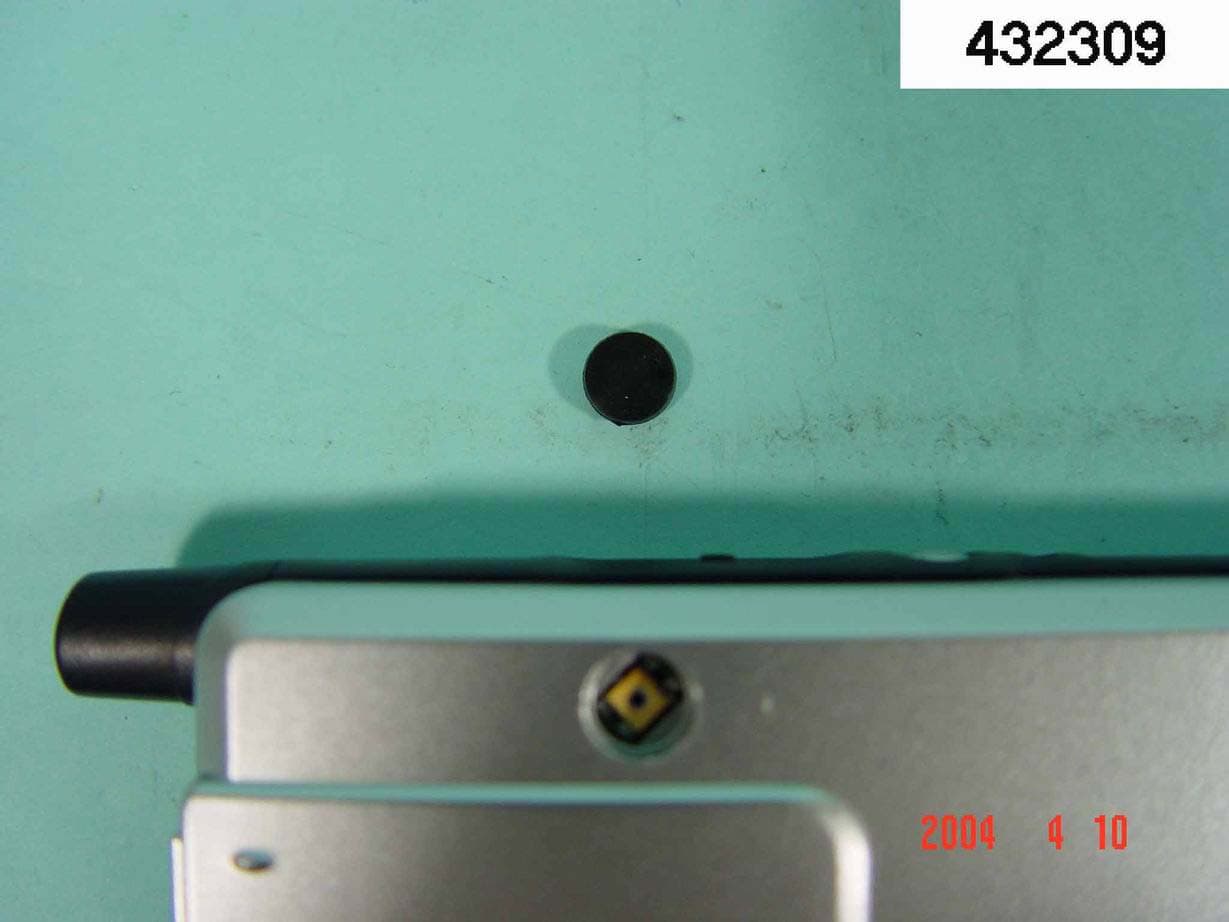
Click to zoom
Application Details
- Equipment Class
- PCE - PCS Licensed Transmitter held to ear
- Date of Grant
- May 24, 2004
- Application Purpose
- Original Equipment
- Date of Application
- May 24, 2004
- Equipment Note
- PDA Phone
- Frequency Range
- 1850.20000000 - 1909.80000000
- Country
- United States
Documents & Files
Document Text
Text extracted from the exhibit documents filed with the FCC. Open a document above to read the original.
Users Manual
NOTE This equipment has been tested and found to comply with the limits for a Class B digital device, pursuant to Part 15 of the FCC Rules. These limits are designed to provide reasonable protection against harmful interference in a residential installation. This equipment generates, uses and can radiated radio frequency energy and, if not installed and used in accordance with the instructions, may cause harmful interference to radio communications. However, there is no guarantee that interference will not occur in a particular installation If this equipment does cause harmful interference to radio or television reception, which can be determined by turning the equipment off and on, the user is encouraged to try to correct the interference by one or more of the following measures: -Reorient or relocate the receiving antenna. -Increase the separation between the equipment and receiver. -Connect the equipment into an outlet on a circuit different from that to which the receiver is connected. -Consult the dealer or an experienced radio/TV technician for help. Changes or modifications not expressly approved by the party responsible for compliance could void the user‘s authority to operate the equipment. The antenna(s) used for this transmitter must not be co-located or operating in conjunction with any other antenna or transmitter. This EUT is incompliance with SAR for general population /uncontrolled exposure limits in ANSI/IEEE C95.1-1999 and had been tested in accordance with the measurement methods and procedures specified in OET Bulletin 65 Supplement C. P P M M X X - - 7 7 0 0 0 0 Q Q u u i i c c k k S S t t a a r r t t G G u u i i d d e e Package Contents ______________________________________ 1 Appearances __________________________________________ 2 Front ____________________________________________ 2 Top _____________________________________________ 3 Right ____________________________________________ 3 Back ____________________________________________ 4 Use for the First Time ___________________________________ 5 Install Supporting Backboard _________________________ 5 Install Battery _____________________________________ 6 Charging and Power Supply __________________________ 8 Screen Alignment __________________________________ 10 Turn on Screen ____________________________________ 10 Power On and Off ______________________________________ 10 Sleep Mode _______________________________________ 10 Reboot ___________________________________________ 11 Use Cell Phone ________________________________________ 12 Turn the Phone On and Off___________________________ 13 Bluetooth Wireless Transmission __________________________ 14 Bluetooth Connection Function Setup __________________ 14 Pair _____________________________________________ 16 Exchange vCards __________________________________ 17 File Exchange _____________________________________ 17 Serial Port ________________________________________ 18 Bluetooth Headset __________________________________ 19 Appendix: Declaration of Conformity ______________________ 20 1 Thank you very much for purchasing this product. This document mainly provides you the references needed when you use this product for the first time. Meanwhile, hardware descriptions will also help you to get familiar with every basic function quickly. Package Contents Pocket PC, stylus, USB cradle (including USB cable), AC adapter, headset, companion CD, leather case, user manual. n USB cradle o AC Adapter p USB Cable q Headset r Stylus s Pocket PC When this product was shipped, the charger’s supporting backboard and cradle were packaged separately. After open the package, please install the backboard into the slot on the cradle as shown in the figure above. Remind you that, once the backboard is installed, you cannot take it off. Otherwise, the blackboard’s safety hook will be broken and cannot be used again. n op q rs 2 Appearances Front 1 Indicator 2 Power Button 3 Cell Phone Speaker 4 Antenna 5 Depends on the program that is running at the time, it can be used as volume adjusting or windows scrolling button. 6 Recording Button 7 Reset Button 8 Infrared Port 9 Headset Jack 10 Send Button 11 Microphone 12 “Contact” Hot Key 13 Navigation Button 14 “Today Screen” Hot Key 15 Speaker 16 End Button 17 Touch Panel Status icons on the navigation bar: Cell Phone Off Cell Phone On GPRS is Online 4 2 1 17 16 15 14 13 12 11 9 10 3 6 5 8 7 3 Top CF Card Slot (Compact Flash) Inside of dust-proof cover Right 1 Stylus slot, pull to take out stylus. 2 SD/MMC card slot on the side of the Pocket PC. 1 2 4 Back 1 Main battery lock, follow the illustrations on Pocket PC to use. 2 Main battery, follow the arrow’s direction to slide and release it. Merchandise label on the top of battery cover. 3 Back-up power switch, follow the illustrations on Pocket PC to use. 4 SIM card slot, follow the illustrations indicated on Pocket PC to use. 5 Cradle connection port y Please note carefully! 1. You need to turn on back-up power switch when you use this Pocket PC for the first time. When back-up power switch is set to be “ON”, the system operation will temporarily rely on back-up battery to supply its power if you need to pull out or replace main battery. Back-up battery is charged by AC adapter or main battery. 2. If back-up power switch is set to be “OFF”, the back-up battery will not function. Once the main battery is taken out, the Pocket PC will only retain Microsoft Windows and manufacture’s pre-installed programs. Any other data input, programs newly installed, and customised settings setup by you will be lost. 1 2 3 4 5 2 5 Use for the First Time Install Supporting Backboard When this product was shipped, the charger’s supporting backboard and cradle were packaged separately. After open the package, please install the backboard into the slot on the cradle as shown in the figure above. Remind you that, once the backboard is installed, you cannot take it off. Otherwise, the blackboard’s safety…
Text truncated - open the document above for the full version.
Users Manual
NOTE This equipment has been tested and found to comply with the limits for a Class B digital device, pursuant to Part 15 of the FCC Rules. These limits are designed to provide reasonable protection against harmful interference in a residential installation. This equipment generates, uses and can radiated radio frequency energy and, if not installed and used in accordance with the instructions, may cause harmful interference to radio communications. However, there is no guarantee that interference will not occur in a particular installation If this equipment does cause harmful interference to radio or television reception, which can be determined by turning the equipment off and on, the user is encouraged to try to correct the interference by one or more of the following measures: -Reorient or relocate the receiving antenna. -Increase the separation between the equipment and receiver. -Connect the equipment into an outlet on a circuit different from that to which the receiver is connected. -Consult the dealer or an experienced radio/TV technician for help. Changes or modifications not expressly approved by the party responsible for compliance could void the user‘s authority to operate the equipment. The antenna(s) used for this transmitter must not be co-located or operating in conjunction with any other antenna or transmitter. This EUT is incompliance with SAR for general population /uncontrolled exposure limits in ANSI/IEEE C95.1-1999 and had been tested in accordance with the measurement methods and procedures specified in OET Bulletin 65 Supplement C. FCC RF Exposure Information Body-worn Operation This device was tested for typical body-worn operations. To comply with FCC RF exposure requirements, a minimum separation distance of 1.5 cm must be maintained between the user’s body and the handset, including the antenna. Third-party belt-clips, holsters, and similar accessories used by this device should not contain any metallic components. Body-worn accessories that do not meet these requirements may not comply with FCC RF exposure requirements and should be avoided. For more information about RF exposure, please visit the FCC website at www.fcc.gov P P M M X X - - 7 7 0 0 0 0 Q Q u u i i c c k k S S t t a a r r t t G G u u i i d d e e Package Contents ______________________________________ 1 Appearances __________________________________________ 2 Front ____________________________________________ 2 Top _____________________________________________ 3 Right ____________________________________________ 3 Back ____________________________________________ 4 Use for the First Time ___________________________________ 5 Install Supporting Backboard _________________________ 5 Install Battery _____________________________________ 6 Charging and Power Supply __________________________ 8 Screen Alignment __________________________________ 10 Turn on Screen ____________________________________ 10 Power On and Off ______________________________________ 10 Sleep Mode _______________________________________ 10 Reboot ___________________________________________ 11 Use Cell Phone ________________________________________ 12 Turn the Phone On and Off___________________________ 13 Bluetooth Wireless Transmission __________________________ 14 Bluetooth Connection Function Setup __________________ 14 Pair _____________________________________________ 16 Exchange vCards __________________________________ 17 File Exchange _____________________________________ 17 Serial Port ________________________________________ 18 Bluetooth Headset __________________________________ 19 Appendix: Declaration of Conformity ______________________ 20 1 Thank you very much for purchasing this product. This document mainly provides you the references needed when you use this product for the first time. Meanwhile, hardware descriptions will also help you to get familiar with every basic function quickly. Package Contents Pocket PC, stylus, USB cradle (including USB cable), AC adapter, headset, companion CD, leather case, user manual. n USB cradle o AC Adapter p USB Cable q Headset r Stylus s Pocket PC When this product was shipped, the charger’s supporting backboard and cradle were packaged separately. After open the package, please install the backboard into the slot on the cradle as shown in the figure above. Remind you that, once the backboard is installed, you cannot take it off. Otherwise, the blackboard’s safety hook will be broken and cannot be used again. n op q rs 2 Appearances Front 1 Indicator 2 Power Button 3 Cell Phone Speaker 4 Antenna 5 Depends on the program that is running at the time, it can be used as volume adjusting or windows scrolling button. 6 Recording Button 7 Reset Button 8 Infrared Port 9 Headset Jack 10 Send Button 11 Microphone 12 “Contact” Hot Key 13 Navigation Button 14 “Today Screen” Hot Key 15 Speaker 16 End Button 17 Touch Panel Status icons on the navigation bar: Cell Phone Off Cell Phone On GPRS is Online 4 2 1 17 16 15 14 13 12 11 9 10 3 6 5 8 7 3 Top CF Card Slot (Compact Flash) Inside of dust-proof cover Right 1 Stylus slot, pull to take out stylus. 2 SD/MMC card slot on the side of the Pocket PC. 1 2 4 Back 1 Main battery lock, follow the illustrations on Pocket PC to use. 2 Main battery, follow the arrow’s direction to slide and release it. Merchandise label on the top of battery cover. 3 Back-up power switch, follow the illustrations on Pocket PC to use. 4 SIM card slot, follow the illustrations indicated on Pocket PC to use. 5 Cradle connection port y Please note carefully! 1. You need to turn on back-up power switch when you use this Pocket PC for the first time. When back-up power switch is set to be “ON”, the system operation will temporarily rely on back-up battery to supply its power if you need to pull out or replace main battery. Back-up battery is charged by AC adapter or main battery. 2. If back-up power switch is set to be “OFF”, the back-up battery will not function. Once …
Text truncated - open the document above for the full version.
Cover Letter(s)
American Telecommunications Certification Body Inc. 6731 Whittier Ave, McLean, VA 22101 May 10, 2004 RE: EC-EYE Communication and Technology, Inc. FCC ID: RZPPMX7000 After a review of the submitted information, I have a few comments on the above referenced Application. Administrative/General: 1) The block diagram should show the frequencies of all oscillators in the TX device (CFR 2.1033(a)(5)), unless this portion of the device is an OEM part. Please provide either the block diagram for the TX portion, or alternatively provide a parts list that shows that this part is provided by another manufacturer by listing the OEM manufacturer. Note that a block diagram is necessary for both transmitters. 2) The current block diagram makes mention of 802.11b and does not mention anything about Bluetooth. Please provide further detail regarding this issue. Note that inclusion of any 802.11b may require a separate FCC ID for the device. 3) It does not appear that internal photographs were provided underneath all subshields on the device. Please provide. 4) The operational description does not mention anything regarding the Bluetooth portion of the device. Please update. Additionally, it is uncertain if the Bluetooth and Part 24 may operate simultaneously. However, currently it is assumed that simultaneous TX may occur. 5) A schematic of the Bluetooth or GSM portion does not appear to be provided. Please provide, or alternatively if these are manufactured by a different manufacturer the parts list may be updated to show the OEM manufacturer. 6) The Tune Up procedure does not appear to contain any power target values. Please update. 7) Since this device may be considered as a PC Peripheral, then an compliance information sheet should be included in the manual on the same page as the FCC statements (alternatively, this may be shipped with the product as a separate sheet). Please provide. This information should contain the following information regarding DoC compliance: FYI: COMPLIANCE INFORMATION FOR DoC AUTHORIZATIONS (47CFR 2.1077) If a product is tested and authorized under a Declaration of Conformity, a compliance information statement shall be supplied with the product at the time of marketing or importation, containing the following information on a single page: (1) Identification of the product, i.e. name and model number. (2) A statement similar to that contained in Section 15.19(a)(3) that the product complies with Part 15 of the regulations. (3) The identification, by name, address and telephone number, of the responsible party. The responsible party is defined as either the manufacturer, or if the equipment is imported, the importer. The responsible party for a Declaration of Conformity must be located within the United States. --- Continued on Next Page --- z Page 2 May 10, 2004 8) Description of all circuitry and devices provided for determining and stabilizing frequency, for suppression of spurious radiation, for limiting modulation, and for limiting power. 9) The users manual warns against using at less than 20 cm as well as evaluation for SAR. These statements contradict themselves. Please correct. 10) It appears that simultaneous TX EMC results many not have been provided. If the device transmits simultaneously for Bluetooth and GSM, this will be required. 11) It appears that SAR may not have been evaluated for simultaneous TX either. If the device is capable of this, then it should be evaluated for all expected worse case conditions. See attachement. 12) The part 24 Test report explains the power as 30 dBm +/- 2 dBm. Note the FCC expects worse case to be tested, however the test report shows only a 28.3 dBm conducted. Note the tune-up procedure and operational description do not provide this information. It appears the device may not been functioning at maximum power for the test. Please retest/correct all exhibits affected as necessary. 13) For Part 25 antenna conducted tests, it appears a power divider was used. It is expected that the measurement results are corrected for associated cable and power divider. Please explain if this occurred. 14) There appears to be a spurious emission just above the fundamental that was not measured. Please explain and/or measure as necessary. 15) It is uncertain if only 1 battery type will be provided for the device by the manufacturer. Note that each type of battery must be tested. Please explain. 16) It is uncertain if any body worn accessories are being provided. If so, do they contain metal? What spacing from the body do they place the EUT. Note all accessories with Metal should be tested. 17) It is uncertain what levels of GSM/GPRS are contained in this device. Currently the crest factor for both body and head is listed only as 8.3. Please explain. 18) The SAR test report should state the FCC ID of the device being tested. 19) Please explain if the device uses bands for use outside of the U.S., or if it only contains bands as given in this application. 20) Please define the actual distance used for body SAR. Photographs tend to suggest that maybe a spacing of 1.6-1.7 mm was used. This distance will be cited on the grant. 21) Please justify the use of 8.3 vs. 8.0 Crest factor. 22) The entire hot spots should be captured. Certain head plots appear to show areas that may be clipped (Entire hot spot is not shown). This may require remeasurement if adequate explanation can not be given. 23) Dipole calibration appears to be provided for 835 MHz as well. Please explain. 24) FYI.....Section 5.7.4 of the part 15 test report shows the limit at 2.39998 GHz as 54 dBuV/m. Note the limit from 2.39-2.4 GHz is only -20 dBm as the restricted band falls at < 2.39 GHz. Timothy R. Johnson Examining Engineer mailto: [email protected] The items indicated above must be submitted before processing can continue on the above referenced application. Failure to provide the requested information may result in application termination. Correspondence should be conside…
Text truncated - open the document above for the full version.
Cover Letter(s)
Dear Tim, May you check the responses for your comments: 3. Internal photo will be updated 10, 11. the EUT can transmit simtaneously, we have check EMC and SAR, no worse has been found. We will add the SAR plotting for simutaneous Tx. 12. Could you check my last mail and give us your confirmaiton? 13. Yes, we tested it using devider and we did correct the final result considering cable loss and divider loss 14. The pulse comes from BCCH of base station, not from EUT. 15. only one battery for this EUT 16. Only ear phone is provided, only it is included in the testing. 17, 18, 20,21,22,23. SAR report will be updated. Daniel >From: Timothy R. Johnson [mailto:[email protected] ] >Sent: Monday, May 10, 2004 1:52 PM >To: Fred Yang (· ̈ ̈K®p); Daniel Lee (§õ¬K©M) ...snip... >corporate fax: 703-847-6888 > >Message has been scanned by Sporton AntiVirus System with no virus detected. Subject: RE: Review of EC-EYE Communication and Technology, Inc., FCC ID: RZPPMX7000 From: =?big5?B?RGFuaWVsIExlZSBcKKf1rEupTVwp?= <[email protected]> To: "Timothy R. Johnson" <[email protected]>
Cover Letter(s)
Dear Tim, We have uploaded all the modified reports and exhibits, pls double check. I brief your comments as belows: 1. User manual, tune-up procedure have been modified according your comments. 2. Te related exhibits of GSM module will be provided by Chi-Mei. 3. There is no additional BT schematic because E-TEN just used BT chipset on their main board, and they already provided main board schematic. 4. Photo has been updated. 5. We have re-tested the spurious radiation worse case of part 24 by transmittig BT simutaneously, and no new event was found. The statment of no new event has been updated in part 24 report. 6. E-TEN has modified their power target to 28.3 dBm, and tune-up procedure and part 24 product spec have been modified. 7. We have re-tested part of SAR, including BT co-location, body SAR with crest factor 4 (it is GPRS class 10) and SAR report has been modified. 8. The testing distance between EUT and phantom is 1.5 cm (comment item 20). 9. For the comment item 22, though hot spot is on the scanning edge, but there is no warning of " Max SAR outside" in all our head testing. If the real max SAR is outside the scaning area, the DASY4 will show "MAX SAR outside', then we need to re-test the channel. However, the testing for this product , we never found the similar warning. Therefore, we consider our testing data is available. If you find any issue remained for the updated exhibits or reports, pls inform me asap. Thanks a lot for help. B.R. Daniel >From: Timothy R. Johnson [mailto:[email protected] ] >Sent: Monday, May 10, 2004 1:52 PM >To: Fred Yang (· ̈ ̈K®p); Daniel Lee (§õ¬K©M) ...snip... >corporate fax: 703-847-6888 > >Message has been scanned by Sporton AntiVirus System with no virus detected. Subject: RE: Review of EC-EYE Communication and Technology, Inc., FCC ID: RZPPMX7000 From: =?big5?B?RGFuaWVsIExlZSBcKKf1rEupTVwp?= <[email protected]> To: "Timothy R. Johnson" <[email protected]> Page 1 of 1___DUE TO VIRUS 5/20/2004Printed for "Timothy R. Johnson" <[email protected]>
Cover Letter(s)
4. Operational Description & Block Diagram
External Photos
FCC TEST REPORT REPORT NO. : F432309 SPORTON International Inc. PAGE NUMBER : A1 OF A8 TEL : 886-2-2696-2468 ISSUED DATE : A pr. 16, 2004 FAX : 886-2-2696-2255 APPENDIX A. External Product Photograph FCC TEST REPORT REPORT NO. : F432309 SPORTON International Inc. PAGE NUMBER : A2 OF A8 TEL : 886-2-2696-2468 ISSUED DATE : A pr. 16, 2004 FAX : 886-2-2696-2255 FCC TEST REPORT REPORT NO. : F432309 SPORTON International Inc. PAGE NUMBER : A3 OF A8 TEL : 886-2-2696-2468 ISSUED DATE : A pr. 16, 2004 FAX : 886-2-2696-2255 FCC TEST REPORT REPORT NO. : F432309 SPORTON International Inc. PAGE NUMBER : A4 OF A8 TEL : 886-2-2696-2468 ISSUED DATE : A pr. 16, 2004 FAX : 886-2-2696-2255 FCC TEST REPORT REPORT NO. : F432309 SPORTON International Inc. PAGE NUMBER : A5 OF A8 TEL : 886-2-2696-2468 ISSUED DATE : A pr. 16, 2004 FAX : 886-2-2696-2255 FCC TEST REPORT REPORT NO. : F432309 SPORTON International Inc. PAGE NUMBER : A6 OF A8 TEL : 886-2-2696-2468 ISSUED DATE : A pr. 16, 2004 FAX : 886-2-2696-2255 APPENDIX A. External Photographs of EUT FCC TEST REPORT REPORT NO. : F432309 SPORTON International Inc. PAGE NUMBER : A7 OF A8 TEL : 886-2-2696-2468 ISSUED DATE : A pr. 16, 2004 FAX : 886-2-2696-2255 FCC TEST REPORT REPORT NO. : F432309 SPORTON International Inc. PAGE NUMBER : A8 OF A8 TEL : 886-2-2696-2468 ISSUED DATE : A pr. 16, 2004 FAX : 886-2-2696-2255
ID Label/Location Info
Label Sample: Label Placement:
Internal Photos
FCC TEST REPORT REPORT NO. : F432309 SPORTON International Inc. PAGE NUMBER : A1 OF A19 TEL : 886-2-2696-2468 ISSUED DATE : A pr. 16, 2004 FAX : 886-2-2696-2255 APPENDIX B. Internal Photograph FCC TEST REPORT REPORT NO. : F432309 SPORTON International Inc. PAGE NUMBER : A2 OF A19 TEL : 886-2-2696-2468 ISSUED DATE : A pr. 16, 2004 FAX : 886-2-2696-2255 FCC TEST REPORT REPORT NO. : F432309 SPORTON International Inc. PAGE NUMBER : A3 OF A19 TEL : 886-2-2696-2468 ISSUED DATE : A pr. 16, 2004 FAX : 886-2-2696-2255 FCC TEST REPORT REPORT NO. : F432309 SPORTON International Inc. PAGE NUMBER : A4 OF A19 TEL : 886-2-2696-2468 ISSUED DATE : A pr. 16, 2004 FAX : 886-2-2696-2255 FCC TEST REPORT REPORT NO. : F432309 SPORTON International Inc. PAGE NUMBER : A5 OF A19 TEL : 886-2-2696-2468 ISSUED DATE : A pr. 16, 2004 FAX : 886-2-2696-2255 FCC TEST REPORT REPORT NO. : F432309 SPORTON International Inc. PAGE NUMBER : A6 OF A19 TEL : 886-2-2696-2468 ISSUED DATE : A pr. 16, 2004 FAX : 886-2-2696-2255 FCC TEST REPORT REPORT NO. : F432309 SPORTON International Inc. PAGE NUMBER : A7 OF A19 TEL : 886-2-2696-2468 ISSUED DATE : A pr. 16, 2004 FAX : 886-2-2696-2255 FCC TEST REPORT REPORT NO. : F432309 SPORTON International Inc. PAGE NUMBER : A8 OF A19 TEL : 886-2-2696-2468 ISSUED DATE : A pr. 16, 2004 FAX : 886-2-2696-2255 FCC TEST REPORT REPORT NO. : F432309 SPORTON International Inc. PAGE NUMBER : A9 OF A19 TEL : 886-2-2696-2468 ISSUED DATE : A pr. 16, 2004 FAX : 886-2-2696-2255 FCC TEST REPORT REPORT NO. : F432309 SPORTON International Inc. PAGE NUMBER : A10 OF A19 TEL : 886-2-2696-2468 ISSUED DATE : A pr. 16, 2004 FAX : 886-2-2696-2255 FCC TEST REPORT REPORT NO. : F432309 SPORTON International Inc. PAGE NUMBER : A11 OF A19 TEL : 886-2-2696-2468 ISSUED DATE : A pr. 16, 2004 FAX : 886-2-2696-2255 FCC TEST REPORT REPORT NO. : F432309 SPORTON International Inc. PAGE NUMBER : A12 OF A19 TEL : 886-2-2696-2468 ISSUED DATE : A pr. 16, 2004 FAX : 886-2-2696-2255 FCC TEST REPORT REPORT NO. : F432309 SPORTON International Inc. PAGE NUMBER : A13 OF A19 TEL : 886-2-2696-2468 ISSUED DATE : A pr. 16, 2004 FAX : 886-2-2696-2255 FCC TEST REPORT REPORT NO. : F432309 SPORTON International Inc. PAGE NUMBER : A14 OF A19 TEL : 886-2-2696-2468 ISSUED DATE : A pr. 16, 2004 FAX : 886-2-2696-2255 FCC TEST REPORT REPORT NO. : F432309 SPORTON International Inc. PAGE NUMBER : A15 OF A19 TEL : 886-2-2696-2468 ISSUED DATE : A pr. 16, 2004 FAX : 886-2-2696-2255 FCC TEST REPORT REPORT NO. : F432309 SPORTON International Inc. PAGE NUMBER : A16 OF A19 TEL : 886-2-2696-2468 ISSUED DATE : A pr. 16, 2004 FAX : 886-2-2696-2255 FCC TEST REPORT REPORT NO. : F432309 SPORTON International Inc. PAGE NUMBER : A17 OF A19 TEL : 886-2-2696-2468 ISSUED DATE : A pr. 16, 2004 FAX : 886-2-2696-2255 FCC TEST REPORT REPORT NO. : F432309 SPORTON International Inc. PAGE NUMBER : A18 OF A19 TEL : 886-2-2696-2468 ISSUED DATE : A pr. 16, 2004 FAX : 886-2-2696-2255 FCC TEST REPORT REPORT NO. : F432309 SPORTON International Inc. PAGE NUMBER : A19 OF A19 TEL : 886-2-2696-2468 ISSUED DATE : A pr. 16, 2004 FAX : 886-2-2696-2255
RF Exposure Info
© 2003 SPORTON International Inc..SAR Testing Lab This report shall not be reproduced except in full, without the written approval of Sporton. Rev.01 Tel:886-22696-2468 Fax:886-2-2696-2255 FCC SAR Test Report Test Report No ﹕ O432309-F Specific Absorption Rate (SAR) Test Report for EC-EYE Communication and Technology Inc. on the Pocket PC Report No. : O432309-F Trade Name : nPhone Model Name : PMX700 FCC ID : RZPPMX700 Date of Testing : Mar.29 and May 13, 2004 Date of Report. : May 14, 2004 Date of Review : May 14, 2004 The test results refer exclusively to the presented test model/sample only. Without written approval of SPORTON International Inc., the test report shall not be reproduced except in full. SPORTON International Inc. 6F, No.106, Sec. 1, Hsin Tai Wu Rd., Hsi Chih, Taipei Hsien, Taiwan, R.O.C. © 2003 SPORTON International Inc..SAR Testing Lab This report shall not be reproduced except in full, without the written approval of Sporton. Rev.01 Tel:886-22696-2468 Fax:886-2-2696-2255 FCC SAR Test Report Test Report No ﹕ O432309-F Table of Contents 1. Statement of Compliance --------------------------------------------------------------------------------------- 1 2. Administration Data---------------------------------------------------------------------------------------------- 2 2.1 Testing Laboratory--------------------------------------------------------------------------------------------- 2 2.2 Detail of Applicant--------------------------------------------------------------------------------------------- 2 2.3 Detail of Manufacturer---------------------------------------------------------------------------------------- 2 2.4 Application Detail---------------------------------------------------------------------------------------------- 2 3.General Information ----------------------------------------------------------------------------------------------- 3 3.1 Description of Device Under Test (DUT)------------------------------------------------------------------- 3 3.2 Applied Standards:--------------------------------------------------------------------------------------------- 6 3.3 Device Category and SAR Limits---------------------------------------------------------------------------- 7 3.4 Test Conditions:------------------------------------------------------------------------------------------------ 7 3.4.1 Ambient Condition------------------------------------------------------------------------------------- 7 3.4.2 Test Configuration------------------------------------------------------------------------------------- 7 4.Specific Absorption Rate (SAR)------------------------------------------------------------------------------- 8 4.1 Introduction----------------------------------------------------------------------------------------------------- 8 4.2. SAR Definition------------------------------------------------------------------------------------------------- 8 5. SAR Measurement Setup--------------------------------------------------------------------------------------- 9 5.1.DASY4 E-Field Probe System------------------------------------------------------------------------------- 10 5.1.1.ET3DV6 E-Field Probe Specification-------------------------------------------------------------- 11 5.1.2 ET3DV6 E-Field Probe Calibration---------------------------------------------------------------- 11 5.2 DATA Acquisition Electronics (DAE)----------------------------------------------------------------------- 12 5.3 Robot------------------------------------------------------------------------------------------------------------ 13 5.4 Measurement Server------------------------------------------------------------------------------------------ 13 5.5 SAM Twin Phantom------------------------------------------------------------------------------------------- 13 5.6. Device Holder for SAM Twin Phantom-------------------------------------------------------------------- 15 5.7 Data Storage and Evaluation-------------------------------------------------------------------------------- 16 5.7.1 Data Storage------------------------------------------------------------------------------------------- 16 5.7.2 Data Evaluation--------------------------------------------------------------------------------------- 16 5.8. Test Equipment Li…
Text truncated - open the document above for the full version.
Contact Information
Applicant
Orson B. Yu(R&D Director)
Technical Contact
Sporton International Inc.Daniel Lee
[email protected]886-3-327-3456
No.52, Hwa-Ya 1st Rd. · Tao Yuan Hsien · Taiwan
Non-Technical Contact
Sporton International Inc.Daniel Lee
[email protected]886-3-327-3456
Test Firm
Sporton International Inc.W Huang
Technical Specifications
| # | Rule Parts | Frequency Range | Power Output | Emission | Tolerance |
|---|---|---|---|---|---|
| 1 | 24E | 1.85 GHz - 1.91 GHz | 411.00 mW | 300KGXW | 0.0400000000 ppm |