RZTGMSG01Guardian Sentinel and Guardian Sentinel GPS
GMC Guardian Mobility Corporation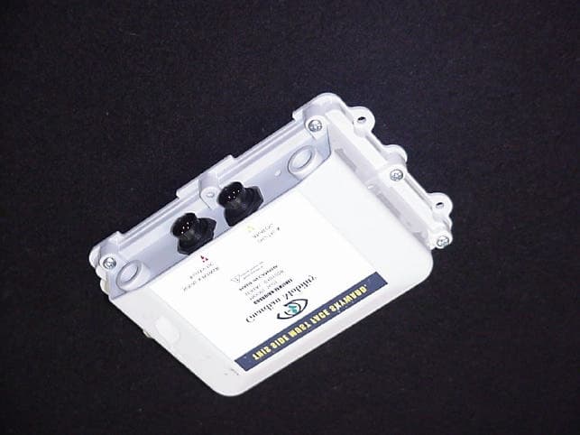
Click to zoom
Application Details
- Equipment Class
- TNB - Licensed Non-Broadcast Station Transmitter
- Date of Grant
- Sep 06, 2004
- Application Purpose
- Original Equipment
- Date of Application
- Sep 06, 2004
- Equipment Note
- Guardian Sentinel and Guardian Sentinel GPS
- Frequency Range
- 1611.25000000 - 1618.75000000
- Country
- Canada
Documents & Files
Document Text
Text extracted from the exhibit documents filed with the FCC. Open a document above to read the original.
Users Manual
GMC GUARDIAN MOBILITY CORPORATION Guardian Sentinel™ and Guardian Sentinel GPS™ Installation Guide & User’s Manual Copyright Copyright © GMC Guardian Mobility Corporation 2004. All rights reserved. Guardian Mobility, Guardian Sentinel, the Guardian Mobility logo, and the Guardian Sentinel logo are trademarks of GMC Guardian Mobility Corporation, and may be registered in some jurisdictions. Disclaimer GMC Guardian Mobility Corporation and its suppliers assume no responsibility for any damage or loss resulting from the use of this handbook. GMC Guardian Mobility Corporation and its suppliers assume no responsibility for any loss or claims by third parties which may arise through the use of this software. GMC Guardian Mobility Corp. and its suppliers assume no responsibility for any damage or loss caused by deletion of data as a result of malfunction, dead battery, or repairs. Important: Please read the Guardian Mobility End User Software License Agreement before using the accompanying software program(s). Using any part of the software indicates that you accept the terms of the Guardian Mobility End User Software License Agreement. All data and information contained in or disclosed by this document are confidential and proprietary information of GMC Guardian Mobility Corporation and its affiliates and all rights therein are expressly reserved. By accepting this material, the recipients agree that this material and the information contained therein are held in confidence and in trust and will not be used, copied, reproduced in whole or in part, nor its contents revealed in any manner to others without the express written permission of GMC Guardian Mobility Corporation. NOTICE This equipment complies with the FCC RF Exposure Limits. A minimum of 20 centimeters (8 inches) separation between the device and the user and all other persons should be maintained. Version 1 © 2004 GMC Guardian Mobility Corporation 15 Capella Court. • Unit 116 Ottawa, Ontario, Canada, K2E 7X1 www.guardianmobility.com GUARDIAN SENTINEL USER MANUAL 1 Table of Contents ABOUT THIS GUIDE ................................................................................................... 3 INTRODUCTION TO THE GUARDIAN SENTINEL .............................................. 4 S ETUP O VERVIEW ........................................................................................................... 5 PARTS DESCRIPTIONS .............................................................................................. 6 PARTS LIST AND DESCRIPTION...................................................................................... 7 SETTING UP THE GUARDIAN SENTINEL............................................................. 9 O VERVIEW ....................................................................................................................... 9 WHAT YOU WILL NEED.................................................................................................. 9 POWER REQUIREMENTS................................................................................................. 9 POWER CONSUMPTION PROFILE..................................................................................... 10 CONNECTOR DIAGRAM................................................................................................. 10 LED BEHAVIOUR DESCRIPTION.................................................................................. 11 USING THE GUARDIAN SENTINEL CONFIGURATION WIZARD................................... 12 GUARDIAN SENTINEL CONFIGURATION WIZARD HARDWARE AND SOFTWARE REQUIREMENTS.............................................................................................................. 12 INSTALLING THE GUARDIAN SENTINEL CONFIGURATION WIZARD............................... 12 OPERATION FLOW OF THE GUARDIAN SENTINEL CONFIGURATION WIZARD SOFTWARE ........................................................................................................................................ 13 THE GUARDIAN SENTINEL CONFIGURATION WIZARD STEP BY STEP....................... 15 THE USAGE SCREEN................................................................................................... 16 CONFIGURING AN RS-232 SENSOR............................................................................. 17 C ONFIGURING A D IGITAL S ENSOR ............................................................................. 18 CONFIGURING AN ANALOG SENSOR.......................................................................... 19 A NALOG SENSOR EXAMPLE ............................................................................................ 20 CONFIGURING THE SCHEDULER................................................................................. 21 S UMMARY I NFORMATION / S AVING THE C ONFIGURATION ........................................ 22 DOWNLOADING THE CONFIGURATION....................................................................... 23 CONNECTING SENSORS TO THE GUARDIAN SENTINEL............................................... 24 GUARDIAN SENTINEL USER MANUAL © 2004 GMC Guardian Mobility Corporation - Confidential 2 TURNING ON THE GUARDIAN SENTINEL...................................................................... 24 VIEWING TRANSMISSIONS.................................................................................... 25 THE GUARDIAN MOBILITY BACKOFFICE SERVER..................................................... 25 MAIN MENU.................................................................................................................... 25 M ODIFYING P ASSWORD AND A CCOUNT I NFORMATION ................................................. 25 LISTING MESSAGES (TRANSMISSIONS)........................................................................... 26 LISTING GUARDIAN SENTINEL AND GUARDIAN SENTINEL GPS UNITS......................... 27 CREATING NEW AND CHANGING EXISTING ROUTES....................................................…
Text truncated - open the document above for the full version.
Users Manual
GMC Guardian Mobility Corporation 15 Capella Court, Suite 116 Ottawa, Ontario Canada K2E 7X1 Tel: (613) 225 8885 x359 Fax: (613) 225 7762 email: [email protected] Dear Customer, Thank you for purchasing the Guardian Sentinel. We are committed to your success in implementing and using the Guardian Sentinel and its associated infrastructure. Here is what we have put in place to support you: 1. We have created a User Guide and Installation Manual, which will be available from our secure customer area on our website. The information on how to access the customer area and a userid and password will be forwarded to you via email from your Guardian Mobility support manager. 2. You call email our support team at [email protected] 3. You can call our support team at 613 225 8885 x 332. 4. Our support manager is Tim Irwin. His e-mail is [email protected] 5. Please keep your account representative or business manager up to date on special support requirements 6. You can contact me at [email protected] I would appreciate being apprised of any issues of importance to you, especially any comments that you might have on your support experience or support requirements. I would also like to hear of success stories, and of testimonial opportunities. Jean Carr President and CEO GMC Guardian Mobility Corporation www.guardianmobility.com Sentinel Configuration Wizard Quick Install Instructions 1. Uninstall any previous versions of the Sentinel Configuration Wizard (through the Windows control panel choose add/remove programs and select "Sentinel Configuration Wizard") 2. If you have Winzip installed on your computer, copy Sentinel Wizard V2.1.0.zip to a directory where you will find it easily. If you do not have Winzip, save Sentinel Wizard V2.1.0.exe. 3. Open the .zip file or .exe file containing the Sentinel Configuration Wizard. 4. Extract the temporary files to a directory of your choice. By default the self extracting archive will create a new TEMP folder where you copied the file earlier. Navigate to the directory with 3 files including setup.exe 5. Launch setup.exe from the temporary directory Please read the Guardian Sentinel User Manual prior to running the application. Guardian Sentinel Quick Setup Instructions NOTICE This equipment complies with the FCC RF Exposure Limits. A minimum of 20 centimeters (8 inches) separation between the device and the user and all other persons should be maintained. 1. Launch the Sentinel Configuration Wizard. 2. Enable RS232, digital inputs and analog inputs as appropriate. If RS232 is enabled, enter baud rate, number of data bits, parity, number of stop bits and data type. For digital inputs, select whether the Guardian Sentinel is triggered by a rising edge, falling edge or both. For analog inputs enter voltage range of sensor output in the full scale voltage box. If the Guardian Sentinel is to notify the user when an analog sensor has gone above or below a threshold, enter these in the Minimum and Maximum Threshold boxes. 3. Set wake-up parameters (schedule). The unit can be programmed to transmit between every 15 minutes to every 8 weeks. 4. Save configuration summary (On the File menu, Click Save or Save As). 5. Set COM port to correct port (On the Communication menu, Click Com Port Setting) 6. Setup the cabling as follows: Using the Programming 'Y' Cable, connect the DB9 serial connector to the serial port of your PC. If you have a USB port only, you must attach a USB to serial port converter. Connect a power source (9-12V) to the battery connector. Connect the round Conxall connector to port 'A' (labeled 'SERIAL & POWER' with a red ‘A’). • When the unit is first powered all three LEDs light up for an instant. After, the STU LED lights up for a couple of seconds while the STU initializes. 7. Ensure that the programming cable switch is set to Prgm(on) Download configuration through the Communications Menu. Select Send Config. to Sentinel. Once this is completed, your Guardian Sentinel is configured. Click 'Finish.' 8. Set the programming cable switch to Run(off). Initialize the unit by placing it outside where it has a clear view of the sky. Wait 5-15 minutes • The GPS LED blinks as the unit begins acquiring GPS position. After it gets a valid GPS position, or the GPS timer times out, the unit begins transmitting. During this time, the STU LED blinks once every 5 seconds until it is done. The transmission period varies between 4 to 6 minutes since your unit has been programmed to transmit the message three times. 9. Login to http://www.guardianmobility.com/sentinel with you userid & password to check for the initial power-on transmission. (Your back office userid and password will have been sent to you via e-mail) GMC GUARDIAN MOBILITY CORPORATION License Agreement for use of Guardian Sentinel or Sentinel GPS (“Device” or “Devices”) with related BackOffice and Wireless Communication Services (“Services”) BEFORE USING THE GUARDIAN SENTINEL OR GUARDIAN SENTINEL GPS OR CLICKING ON “ACCEPT” DURING REVIEW OF THIS LICENSE, PLEASE CAREFULLY READ THIS LICENSE, WHICH CONTAINS THE TERMS AND CONDITIONS UNDER WHICH YOU ARE ACQUIRING A LICENSE TO USE THE ACCOMPANYING GUARDIAN SENTINEL OR GUARDIAN SENTINEL GPS AND RELATED BACKOFFICE AND WIRELESS COMMUNICATION SERVICES. IF YOU DO NOT ACCEPT THE TERMS AND CONDITIONS OF THE LICENSE, PLEASE DO NOT INSTALL OR USE THE GUARDIAN SENTINEL OR GUARDIAN SENTINEL GPS AND PROMPTLY RETURN THE DEVICE(S) TO THE PLACE AT WHICH YOU ACQUIRED IT FOR A FULL REFUND OF ANY LICENSE FEE PAID. IF YOU INSTALL OR USE IT, YOU WILL BE ACQUIRING A LICENSE TO USE THE GUARDIAN SENTINEL OR GUARDIAN SENTINEL GPS AND RELATED BACKOFFICE AND WIRELESS COMMUNICATION SERVICES IN ACCORDANCE WITH THE TERMS AND CONDITIONS OF THIS LICENSE, AND YOU WILL BE CONSIDERED TO HAVE ACCEPTED AND AGREED TO THESE TERMS AND CONDITIONS. 1. License and Payment In consideration and subject to the due payments, and subject to the terms of this Agr…
Text truncated - open the document above for the full version.
Cover Letter(s)
AGENCY AGREEMENT Federal Communications CommissionMarch 15, 2004 P.O. Box 429 Columbia, MD 21045 Gentlemen: I hereby appoint United States Technologies to act as our agent in the preparation of an application for equipment authorization of the Guardian Sentinel GPS, Model Number GM-SG01 under Part 25 of the FCC Rules and Regulations. I certify that the enclosed information is representative of the device or system for which authorization is sought, the information in the User's Manual will be provided with each unit distributed by the applicant and the described label will be affixed to each unit distributed by the applicant. I certify that appropriate arrangements have been made to assure that production units of this equipment bearing the name and FCC IDENTIFIER listed in this application will continue to comply with the Commission's requirements. I further certify by signature below that no party (per 47 CFR 1.2002(b)) to the application is subject to a denial of Federal benefits, including FCC benefits, pursuant to Section 5301 of the Anti-Drug Abuse Act of 1988, 21 U.S.C. 853(a). This appointment includes the authority to complete FCC Form 731 on our behalf and sign the application as an authorized agent. I appreciate your attention to this matter.
Cover Letter(s)
CONFIDENTIALITY REQUEST Federal Communications CommissionMarch 15, 2004 Equipment Authorization Branch 7435 Oakland Mills Road Columbia, MD 21046 Gentlemen: GMC Guardian Mobility Corporation respectfully requests confidentiality of certain materials provided with the submission of the Guardian Sentinel GPS under FCC ID: RZTGMSG01 in accordance with FCC Regulations 0.459. The confidentiality request applies to the following: Schematics Parts List Theory of Operation These items are considered as Trade Secrets and therefore public access to the proprietary material could possible result in duplication of equipment that could severely damage the company's business advantage. I appreciate your assistance in this matter.
Cover Letter(s)
ATCB Attn: Mr. William Graff Re: Guardian Mobility Certification Application Bill, Below is the response to your comments: 1.) Please remove all RF shields when making internal photographs. Updated photos have been uploaded. 2.) The two part label statement is incorrect. The correct label language for this Licensed radio service can be found in 15.19(a)(1). The label has been updated to the correct language 3.) All Licensed radio transmitters must have a Parts list per 2.1033(c)(10). The parts list has been uploaded. Please treat this list with Confidentiality. 4.) Please provide tune up instructions per 2.1033(c)(9). Tune up values as used during production are satisfactory. The tune up procedure has been uploaded. 4.) Please provide voltage and currents through the finals as required by 2.1033(c)(8). This information has been uploaded. 5.) Please provide a description of the modulation as required by 2.1033(c)(13) and 2.1047. This information has been uploaded. 6.) Please provide radiated spurious data to the 10th harmonic as required by 2.1057. When data is more than 20dB below the limit, please indicate such. The report has been modified to reflect data more than 20dB below the limit. 7.) Please modify your RF Exposure exhibit to calculate “S” at 20cm, not a “safe MPE” distance. The corrected data has been uploaded. 8.) Using the definitions in 25.201, kindly identify the type of equipment and it’s expected service. This information has been uploaded. 9.) No Block Diagram or Theory of Operation was uploaded as described in the Confidentiality Request. Please disregard the Confidentiality request for the block Diagram and Theory of Operation. Sincerely, Louis A. Feudi Operations Manager
Cover Letter(s)
American Telecommunications Certification Body Inc. 6731 Whittier Ave, McLean, VA 22101 May 13, 2004 RE: GMC Guardian Mobility Corporation FCC ID: RZTGMSG01 I have a few comments on this Application. 1.) Please remove all RF shields when making internal photographs. 2.) The two part label statement is incorrect. The correct label language for this Licensed radio service can be found in 15.19(a)(1). 3.) All Licensed radio transmitters must have a Parts list per 2.1033(c)(10). 4.) Please provide tune up instructions per 2.1033(c)(9). Tune up values as used during production are satisfactory. 5.) Please provide voltage and currents through the finals as required by 2.1033(c)(8). 6.) Please provide a description of the modulation as required by 2.1033(c)(13) and 2.1047. 7.) Please provide radiated spurious data to the 10 th harmonic as required by 2.1057. When data is more than 20dB below the limit, please indicate such. 8.) Please modify your RF Exposure exhibit to calculate “S” at 20cm, not a “safe MPE” distance. 9.) Using the definitions in 25.201, kindly identify the type of equipment and it’s expected service. 10.) No Block Diagram or Theory of Operation was uploaded as described in the Confidentiality Request. William H. Graff President and Director of Engineering mailto: [email protected] The items indicated above must be submitted before processing can continue on the above referenced application. Failure to provide the requested information may result in application termination. Correspondence should be considered part of the permanent submission and may be viewed from the Internet after a Grant of Equipment Authorization is issued. Please do not respond to this correspondence using the email reply button. In order for your response to be processed expeditiously, you must submit your documents through the AmericanTCB.com website. Also, please note that partial responses increase processing time and should not be submitted. Any questions about the content of this correspondence should be directed to the sender.
External Photos
U.S. Technologies, Inc.FCC Part 25 Certification Report Number:04-0025Issue Date: March 31, 2004 Customer: GMC Guardian Mobility Corporation Model: GM-SG01FCC ID: RZTGMSG01 SECTION 3 PHOTOGRAPHS U.S. Technologies, Inc.FCC Part 25 Certification Report Number:04-0025Issue Date: March 31, 2004 Customer: GMC Guardian Mobility Corporation Model: GM-SG01FCC ID: RZTGMSG01 Photo 1.Front View U.S. Technologies, Inc.FCC Part 25 Certification Report Number:04-0025Issue Date: March 31, 2004 Customer: GMC Guardian Mobility Corporation Model: GM-SG01FCC ID: RZTGMSG01 Photo 2.Back View
ID Label/Location Info
U.S. Technologies, Inc.FCC Part 25 Certification Report Number:04-0025Issue Date: March 31, 2004 Customer: GMC Guardian Mobility Corporation Model: GM-SG01FCC ID: RZTGMSG01 RZTGMSG01
Internal Photos
Transmitter board with cover removed
Internal Photos
U.S. Technologies, Inc.FCC Part 25 Certification Report Number:04-0025Issue Date: March 31, 2004 Customer: GMC Guardian Mobility Corporation Model: GM-SG01FCC ID: RZTGMSG01 SECTION 3 PHOTOGRAPHS U.S. Technologies, Inc.FCC Part 25 Certification Report Number:04-0025Issue Date: March 31, 2004 Customer: GMC Guardian Mobility Corporation Model: GM-SG01FCC ID: RZTGMSG01 Photo 3.Bottom Cover Removed U.S. Technologies, Inc.FCC Part 25 Certification Report Number:04-0025Issue Date: March 31, 2004 Customer: GMC Guardian Mobility Corporation Model: GM-SG01FCC ID: RZTGMSG01 Photo 4.Transmitter Board Top U.S. Technologies, Inc.FCC Part 25 Certification Report Number:04-0025Issue Date: March 31, 2004 Customer: GMC Guardian Mobility Corporation Model: GM-SG01FCC ID: RZTGMSG01 Photo 5.Transmitter Board Bottom U.S. Technologies, Inc.FCC Part 25 Certification Report Number:04-0025Issue Date: March 31, 2004 Customer: GMC Guardian Mobility Corporation Model: GM-SG01FCC ID: RZTGMSG01 Photo 6.Connector Board Top U.S. Technologies, Inc.FCC Part 25 Certification Report Number:04-0025Issue Date: March 31, 2004 Customer: GMC Guardian Mobility Corporation Model: GM-SG01FCC ID: RZTGMSG01 Photo 7.Connector Board Bottom U.S. Technologies, Inc.FCC Part 25 Certification Report Number:04-0025Issue Date: March 31, 2004 Customer: GMC Guardian Mobility Corporation Model: GM-SG01FCC ID: RZTGMSG01 Photo 8.Antenna Board Top U.S. Technologies, Inc.FCC Part 25 Certification Report Number:04-0025Issue Date: March 31, 2004 Customer: GMC Guardian Mobility Corporation Model: GM-SG01FCC ID: RZTGMSG01 Photo 9.Antenna Board Bottom U.S. Technologies, Inc.FCC Part 25 Certification Report Number:04-0025Issue Date: March 31, 2004 Customer: GMC Guardian Mobility Corporation Model: GM-SG01FCC ID: RZTGMSG01 Photo 10.Mother Board Top U.S. Technologies, Inc.FCC Part 25 Certification Report Number:04-0025Issue Date: March 31, 2004 Customer: GMC Guardian Mobility Corporation Model: GM-SG01FCC ID: RZTGMSG01 Photo 11.Mother Board Bottom
Parts List/Tune Up Info
Tune Up Procedure GMSG01 requires no Frequency tunes. The crystal is a TCXO qualified in operating range at time of manufacture. Power levels are set as below. 2.3.2 Power The output power shall have two settings selectable by a discrete input to the board, (sampled during power-up), or by command via the serial port. A jumper shall be included on the board to indicate the source of the control. If the jumper setting corresponds to the discrete input control, the discrete input PWR_LVL is sampled during power up to indicate the output power level. Discrete Control Setting (Sampled at power-up) Power Setting OpenLow GroundHigh If the jumper setting corresponds to a serial control, the power level is set according to a value set in the EEPROM. Serial port commands (See Error! Reference source not found.) can modify this EEPROM value. The output power on a 50 ohms load after the power amplifier shall be according to Table 1, Output Power Discrete Control SettingAvg Power (During 1.28 s) High 22dBm +/- 2 dB Low18 dBm +/- 2 dB Table 1, Output Power The power tolerances shall include the temperature and voltage variations as well as the manufacturing tolerances. The power measurement shall be made in a 5 MHz bandwidth centered on the carrier frequency. Closed loop power control should not be required. I/O Connector and Power/Ground connectors may be combined. 9.1 I/O & Power Connector DescriptionRS232 connection for control and test Discrete control pins for test I/O Pins Power pins ConnectorTBD Mating ConnectorTBD 13579 246810 J7-1 RTC EXTERNAL POWER IN J7-2 GROUND J7-3 LED POWER J7-4 LED CONTROL J2-1 POWER IN J2-2 POWER IN J2-3 GROUND J2-4 GROUND J2-5 DIGITAL INPUT 1 J2-6 DIGITAL INPUT 2 J2-7 SERIAL TX (INPUT) J2-8 RTS (INPUT) J2-9 SERIAL RX (OUTPUT) J2-10 CTS (OUTPUT) J4-1 TEST INPUT 1 J4-2 TEST INPUT 2 J4-3 VDIG (ICP - NOT INSTALLED IN PRODUCTION) J4-4 uC RESET (ICP - NOT INSTALLED IN PRODUCTION) J6-1 POWER LEVEL J6-2 GROUND J6-3 POWER LEVEL OVERRIDE J6-4 GROUND 2 13 4 13 24 13 24 J4J6J7 2 13 42 13 4 J3J5 J3-1 NO PIN J3-2 NO PIN J3-3 NO PIN J3-4 NO PIN J5-1 NO PIN J5-2 NO PIN J5-3 NO PIN J5-4 NO PIN J2 (TOP VIEW) Notes: • LED_GND may be connected to board ground. • The cable length between the I/O connector and the DTE will not exceed 20 cm • Unused pins of the connector will be left unconnected Note: • The OEM integrator will keep the power cable length to less than 20 cm with a minimum gauge wire gauge of 20 AWG
RF Exposure Info
SECTION 4 RF EXPOSURE INFORMATION 4.1 RF Safety Requirements to 2.1091 for Mobile Transmitters Power Output The EUT’s maximum expected output power as shown in section 2.6 is Frequency of Fundamental (MHz) Adjusted Measurement (dBm) Measurement (Watt) 1618.8823.110.205 Source Based Time Averaging This information has not been included and the MPE calculations specified below do not take into consideration any duty cycle correction. MPE Calculations The limits for this unit (uncontrolled exposure) is 1.0 mW/cm 2 . Taking the RF Density Field Equation: S = (EIRP in mW)/(4 π R 2 ) S = (205 mW)/(4*3.14159*20 2 ) S =205/5026.6 S = 0.04 mW/cm 2 The device should be installed to maintain 20 cm from humans during use. Information regarding installation and use should be contained in the users manual.
Test Report
Voltages and Currents in Final Amplification Circuit Voltages are all 5 VDC and below. The amplifier runs on 5 VDC with peak run current of 500 mA however normal operating current is 375 mA at room temperature. The final power amplifier contains active feedback, which prevents current run-away due to VSWR mismatch (i.e. open or short circuit).
Test Report
MEASUREMENT/TECHNICAL REPORT COMPANY NAME:GNC Guardian Mobility Corporation MODEL:GM-SG01 FCC ID:RZTGMSG01 DATE:March 31, 2004 This report concerns (check one): Original grant X Class II change_____ Equipment type: Transceiver Deferred grant requested per 47 CFR 0.457(d)(1)(ii)? yes_____ No X If yes, defer until:_________________ date N.A. agrees to notify the Commission by N.A. date of the intended date of announcement of the product so that the grant can be issued on that date. Report prepared by: United States Technologies, Inc. 3505 Francis Circle Alpharetta, GA 30004 Phone Number: (770) 740-0717 Fax Number: (770) 740-1508 I certify that I am authorized to sign for the manufacturer and that all of the statements in this report and in the Exhibits attached hereto are true and correct to the best of my knowledge and belief: UNITED STATES TECHNOLOGIES, INC. (AGENT RESPONSIBLE FOR TEST): By: Name: Louis A Feudi Title: Operations Manager Date: March 31, 2004 GMC Guardian Mobility Corporation 116-15 Capella Court Ottawa, ON K2E 7X1 Canada By: Name: Title: Date: This report shall not be reproduced except in full. This report may be copied in part only with the prior written approval of U.S. Technologies. The results contained in this report are subject to the adequacy and representative character of the sample provided. ii. TABLE OF CONTENTS AGENCY AGREEMENT LETTER OF CONFIDENTIALITY SECTION 1 GENERAL INFORMATION 1.1Product Description 1.2Related Submittal(s) SECTION 2 TESTS AND MEASUREMENTS 2.1Configuration of Tested EUT 2.2Test Facility 2.3Test Equipment 2.4Modifications 2.5Antenna Description 2.6RF Power Output 2.7Modulation Characteristics 2.8Occupied Bandwidth 2.9Spurious Emissions at Antenna Terminals 2.10Field Strength of Spurious Radiation 2.11 Frequency Stability 2.12 Emissions from Mobile Earth Stations for Protection of Aeronautical Radionavigation- Satellite Service. SECTION 3 PHOTOGRAPHS SECTION 4 RF EXPOSURE INFORMATION SECTION 5 LABELING INFORMATION SECTION 6 BLOCK DIAGRAMS/SCHEMATICS SECTION 7 USER’S MANUAL U.S. Technologies, Inc.FCC Part 25 Certification Report Number:04-0025Issue Date: March 31, 2004 Customer: GMC Guardian Mobility Corporation Model: GM-SG01FCC ID: RZTGMSG01 LIST OF FIGURES AND TABLES FIGURES 1)Test Configuration 2) Photograph(s) for Spurious Emissions 3) RF Power Output 4) Modulation Characteristics 5) Occupied Bandwidth 6) Spurious Emissions at Antenna Terminals 7) Emissions from Mobile Earth Stations for Protection of Aeronautical Radionavigation- Satellite Service. 8) a – f Schematics TABLES 1)EUT and Peripherals 2) Test Instruments 3) RF Power Output 4) Field Strength of Spurious Emissions 5) Frequency Stability U.S. Technologies, Inc.FCC Part 25 Certification Report Number:04-0025Issue Date: March 31, 2004 Customer: GMC Guardian Mobility Corporation Model: GM-SG01FCC ID: RZTGMSG01 1 SECTION 1 GENERAL INFORMATION U.S. Technologies, Inc.FCC Part 25 Certification Report Number:04-0025Issue Date: March 31, 2004 Customer: GMC Guardian Mobility Corporation Model: GM-SG01FCC ID: RZTGMSG01 2 GENERAL INFORMATION 1.1Product Description The Equipment Under Test is the GMC Guardian Mobility Corporation GM-SG01. The EUT is a location-enabled, mobile “user to satellite” transmitter platform built around the Axonn, L.L.C. Model G-SENS STU satellite module. The unit operates at the following 4 transmit frequencies: 1611.25 MHz, 1613.75 MHz, 1616.26 MHz, & 1618.75 MHz. The GM-SG01 provides a modem functionality to transmit bursts of data containing user information, including GPS location, to a satellite constellation. The satellites operate as linear transponders and the signal is redirected to a ground station where the user information is extracted and distributed. For the purpose of this test the EUT was placed into a high power (+22 dBm) constant TX mode of operation. U.S. Technologies, Inc.FCC Part 25 Certification Report Number:04-0025Issue Date: March 31, 2004 Customer: GMC Guardian Mobility Corporation Model: GM-SG01FCC ID: RZTGMSG01 3 1.2Related Submittal(s)/Grant(s) The EUT is subject to the following authorizations: a)Certification as a transmitter as specified by Part 25. The information contained in this report is presented for the Part 25 Certification authorization(s) for the EUT. U.S. Technologies, Inc.FCC Part 25 Certification Report Number:04-0025Issue Date: March 31, 2004 Customer: GMC Guardian Mobility Corporation Model: GM-SG01FCC ID: RZTGMSG01 4 SECTION 2 TEST AND MEASUREMENTS U.S. Technologies, Inc.FCC Part 25 Certification Report Number:04-0025Issue Date: March 31, 2004 Customer: GMC Guardian Mobility Corporation Model: GM-SG01FCC ID: RZTGMSG01 5 TEST AND MEASUREMENTS 2.1 Configuration of Tested System Prepared in accordance with the requirements of the FCC Rules and Regulations Part 2 & 25. All measurements are peak unless stated otherwise. The video filter associated with the spectrum analyzer was off throughout the evaluation process. Interconnecting cables were manipulated as necessary to maximize emissions. A block diagram of the tested system is shown in Figure 1. Test configuration photographs for spurious emissions are shown in Figure 2. 2.2 Test Facility Testing was performed at US Tech's measurement facility at 3505 Francis Circle, Alpharetta, GA. This site has been fully described and registered by the FCC under Registration Number 91037. Additionally, this site has also been fully described and submitted to Industry Canada (IC), and has been approved under file IC2982. 2.3 Test Equipment Table 2 describes test equipment used to evaluate this product. 2.4 Modifications No modifications were made by US Tech to bring the EUT into compliance with FCC Part 25 limits for the transmitter portion of the EUT. U.S. Technologies, Inc.FCC Part 25 Certification Rep…
Text truncated - open the document above for the full version.
Contact Information
Applicant
Johannes Hill(V.P. Product Management)
Technical Contact
US TechnologiesLou Feudi
[email protected]770 740 0717
3505 Francis Circle · Alpharette, Georgia · United States
Test Firm
US TechSandy McEnery
Technical Specifications
| # | Rule Parts | Frequency Range | Power Output | Emission | Tolerance |
|---|---|---|---|---|---|
| 1 | 25 | 1.61 GHz - 1.62 GHz | 205.00 mW | 2M31G1D | 6.3000000000 ppm |