RZZRT24Remote Control Transmitter
ELDAT GmbH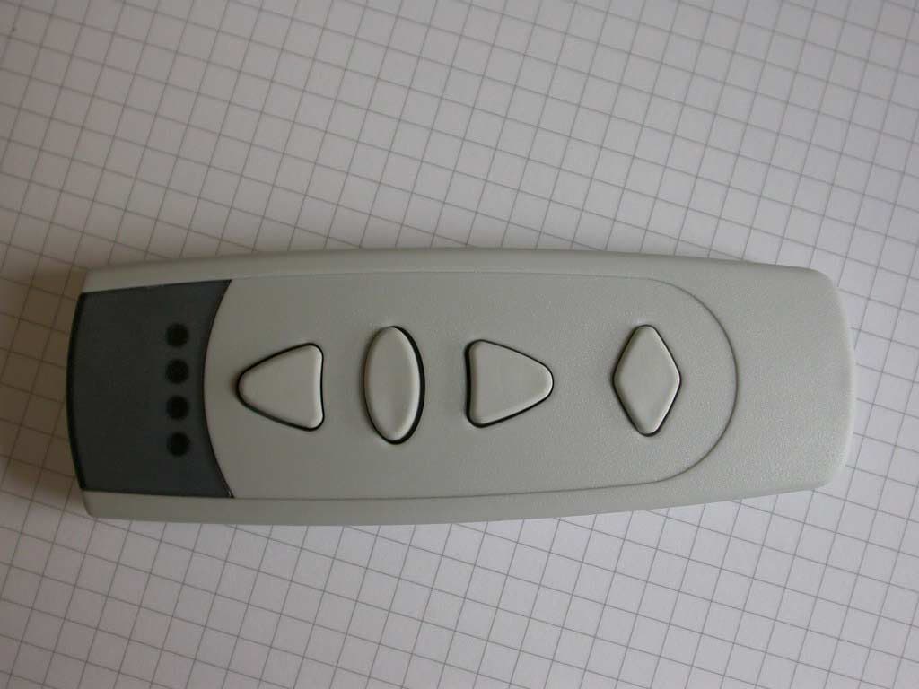
Click to zoom
Application Details
- Equipment Class
- DSC - Part 15 Security/Remote Control Transmitter
- Date of Grant
- Oct 18, 2005
- Application Purpose
- Original Equipment
- Date of Application
- Oct 18, 2005
- Equipment Note
- Remote Control Transmitter
- Frequency Range
- 315.00000000 - 315.00000000
- Company
- ELDAT GmbH
- Country
- Germany
Documents & Files
Document Text
Text extracted from the exhibit documents filed with the FCC. Open a document above to read the original.
Users Manual
RT24 Hand Transmitter RT24-3101M-01 RT24-3104M-01 LED OPEN STOP Channel selector Mounting plate CLOSE RT24-3101M-03 RT24-3104M-03 LED ON Channel selector Mounting plate OFF Operating instructions Safety advice Carefully read through these instructions before using the transmitter! Note also the operating instructions of the radio control(s)! The hand transmitter should only be oper- ated within sight of the devices to be con- trolled! Otherwise persons could be placed in danger! Have faulty hand transmitters checked by the manufacturer! Do not make any unauthorized alterations or modifications to the hand transmitter! Models / Features RT24-3101M-01: 1 radio channel for controlling one device, Functions: OPEN, STOP, CLOSE RT24-3101M-03: 1 radio channel for controlling one device, Functions: ON and OFF RT24-3104M-01: 4 radio channels for separate or contempo- raneous controlling (group function) of four devices, Functions: OPEN, STOP, CLOSE RT24-3104M-03: 4 radio channels for separate or contempo- raneous controlling (group function) of four devices, Functions: ON and OFF Package content - Hand transmitter incl. battery - Mounting plate - Programming connector - Screws and anchors - Adhesive pad - Operating instructions Using the hand transmitter Start-up The hand transmitter comes with a battery already installed so, once unpacked, it is ready for immediate use. • Mount the transmitter to the wall using the mounting plate. • Transmit the channel(s) to the radio controls of the devices to be operated. For this read the operating instructions supplied with the radio controls. Note for 4-channel transmitters: channel selection is described in the chapter "Select- ing channel". Selecting channel Only 4-channel transmitters: Using the channel selector button, select the channel of the device to be operated. 2s 2s 2s 2s 2s Channel 1 Channel 2 Channel 3 Channel 4 Channels 1-4 (Group function) Each time you press the channel selector button, you switch to the next channel or to the group function (channel 1 > channel 2 > channel 3 > channel 4 > channels 1-4/ group function > channel 1 etc.). The selected channel is signalled via the LED’s as follows: Channel 1: LED 1 lights up for approx. 2 secs. Channel 2: LED 2 lights up for approx. 2 secs. Channel 3: LED 3 lights up for approx. 2 secs. Channel 4: LED 4 lights up for approx. 2 secs. Channels 1-4: LED’s 1-4 light up for approx 2 secs. (group function) After the first pressing of the channel selector button, the channel used last is selected. Transmitting • Press one of the function buttons (OPEN, STOP, CLOSE or ON, OFF) in order to control the corresponding device. The LED of the corresponding channel briefly lights up. (Only 4-channel transmitters) If the group function is selected, all 4 devices are con- trolled and all 4 LED’s briefly light up at the same time. Troubleshooting • If the LED(s) light up too faintly: change the battery. • If the LED(s) don't light up at all: check that the battery is correctly poled. • If the device still doesn't react: go closer to the radio control or re- transmit the transmitter channels to the radio control. © 2005 Al 73904 0505 US l rights reserved Replacing the battery • Insert a small coin into the slot on the underside of the transmitter. Turn the coin diagonally and carefully press the two halves of the housing apart. • Replace the battery. Use only batteries of type CR2032. Make sure the polarity is correct! • Press the two housing halves together again. Caution! Keep batteries out of reach of children! Changing transmitter codes The hand transmitter comes factory coded. An individual transmitter code is assigned to every channel. You can duplicate or change the coding by transferring the transmitter codes of another transmitter to the hand transmitter. Source transmitterTarget transmitter • Connect the source transmitter and target transmitter using the programming con- nector. • (Only 4-channel transmitters) Select on the source transmitter the channel whose code is to be transferred. • Press and hold one of the function but- tons (OPEN, STOP, CLOSE, ON or OFF) on the source transmitter. • (Only 4-channel transmitters) Select on the target transmitter the channel whose code is to be changed. • Press and hold one of the function but- tons on the target transmitter. If the code has been transferred, the LED’s 1 and 4 (on 4-channel transmitters) or the LED 1 (on single-channel transmitters) on the target transmitter light up. Release the buttons on both transmitters. • (Only 4-channel transmitters) Repeat the code transfer for the other channels. • Remove the programming connector. Note: You can also transfer the codes of other transmitters (e.g. mini transmitters) to the hand transmitter or transmitter codes of the hand transmitter to other transmitters. For each hand transmitter channel only one code is to be transferred. The same transmit- ter code is assigned to every function button of the hand transmitter. Random coding You can also assign a new random code to each channel: • Put the programming connector into the socket and short-circuit one of the outer pins with the middle pin. • (Only 4-channel transmitters) Select the channel whose code is to be changed. • Press and hold one of the function but- tons (OPEN, STOP, CLOSE, ON or OFF). While the new code is generated, the LED’s 1 and 4 (on 4-channel transmit- ters) or the LED 1 (on single-channel transmitters) light up. After 5 secs. re- lease the function button. • (Only 4-channel transmitters) Repeat the random coding for the other channels. • Remove the programming connector. Note: After re-coding you have to transfer the transmitter codes to the radio controls. General information Disposal Dispose of the waste product via a collection point for electronic scrap or via your specialist dealer. Put packaging material into a recycling bin for cardboard and paper. Dispose of used batteries in a container for used batteries or via the specialist t…
Text truncated - open the document above for the full version.
Cover Letter(s)
Request for Confidentiality in accordance with 47 CFR 0.459 Date: 18 July 2005 PHOENIX TEST-LAB GmbH Kˆnigswinkel 10 D32825 Blomberg Germany RE: Certification Application FCC ID: RZZRT24 Please be advised that the following information is to be held confidential on behalf of ELDAT GmbH: • Schematics • Parts Lists • Block Diagram • Technical Description The application contains technical information which ELDAT GmbH deems to be trade secrets and proprietary. If made public, the information might be used to the disadvantage of the applicant in the market place. Thank you for your attention to this matter.
External Photos
FCC ID: RZZRT24 FCC ID: RZZRT24 FCC ID: RZZRT24 FCC ID: RZZRT24 FCC ID: RZZRT24 FCC ID: RZZRT24
ID Label/Location Info
RT24 Hand transmitter RT24-3101M-03 RT24-3104M-03 LED ON Channel selector Mounting plate OFF Function: ON/OFF Transmitter without Stop-Function (without Stop button) Transmitter 1 Channel Transmitter 4 Channel RT24-3101M-01 RT24-3104M-01 LED OPEN STOP Channel selector Mounting plate CLOSE Funktionen: OPEN/STOP/CLOSE Transmitter with Stop- Function (with stop button) Transmitter 1 Channel Transmitter 4 Channel
Test Report
EMV-Pr ̧fzentrum EMI/EMC-Testcenter FCC-ID: Test Report No.: 50530-40219 Page 1 of 23 Pages Straubing, 11 June 2004 T E S T - R E P O R T No. 50530-40219 for RT24 315 MHz ASK Remote Control Transmitter Applicant: ELDAT Gesellschaft f ̧r Elektronik und Datentechnik mbH Test Specification: FCC Code of Federal Regulations, Part 15 Subpart C, Section 15.231 Note: The test data of this report relate only to the individual item which has been tested. This report shall not be reproduced except in full extent without the written approval of the testing laboratory. EMV-Pr ̧fzentrum EMI/EMC-Testcenter FCC-ID: Test Report No.: 50530-40219 Page 2 of 23 Pages Table of Contents 1. Administrative Data.....................................................................................3 2. Identification of Test Laboratory .................................................................4 3. Operation Mode of EUT..............................................................................5 4. Configuration ..............................................................................................6 5. Measuring Methods ....................................................................................7 5.1. Conducted powerline emissions...........................................................8 5.2. Field Strength of Emissions, Prescans in a fully-anechoic Room....................................................................................................9 5.3. Radiated Emission Measurement at Open Area Test Site .................11 6. Photographs Taken During Testing ..........................................................12 7. List of Measurements ...............................................................................16 8. Referenced Regulations ...........................................................................22 Charts taken during testing ...............................................................................23 EMV-Pr ̧fzentrum EMI/EMC-Testcenter FCC-ID: Test Report No.: 50530-40219 Page 3 of 23 Pages 1. Administrative Data Test item (EUT) Type designation RT24 315 MHz ASK Serial number(s): 90128059 Type of equipment: Remote Control Transmitter Parts/accessories: --- FCC-ID: Technical data Frequency range N/A Operational frequency 315 MHz Type of modulation 10K0A1D Pulse frequency N/A Pulse width N/A Antenna Integrated Power supply 3 V lithium battery Applicant: (full address) ELDAT Gesellschaft f ̧r Elektronik und Datentechnik mbH Im Gewerbegebiet 14 D-15711 Zeesen Germany Contract identification: --- Contact person: Mr. Andreas Eidam Manufacturer: Eldat GmbH Application details Receipt of EUT: 25 May 2004 Date of test: June 2004 Note: Responsible for testing: Mr. Martin Steindl Responsible for test report: Mr. Martin Steindl EMV-Pr ̧fzentrum EMI/EMC-Testcenter FCC-ID: Test Report No.: 50530-40219 Page 4 of 23 Pages 2. Identification of Test Laboratory DETAILS OF THE TEST LABORATORY COMPANY NAME: Senton GmbH EMI/EMC Test Center ADDRESS: Aeussere Fruehlingsstrasse 45 D-94315 Straubing Germany LABORATORY ACCREDITATION: DAR-Registration No. TTI-P-G 062/94-01 FCC TEST SITE LISTING 90926 INDUSTRY CANADA TEST SITE REGISTRATION IC 3050 NAME FOR CONTACT PURPOSES: Mr. Johann Roidt TELEPHONE: (+49) (0)9421 5522-0 FAX: (+49) (0)9421 5522-99 PERSONNEL INVOLVED IN THIS TEST REPORT LABORATORY MANAGER: Mr. Johann Roidt RESPONSIBLE FOR TESTING: Mr. Martin Steindl RESPONSIBLE FOR TEST REPORT: Mr. Martin Steindl SUMMARY OF TEST RESULTS The tested sample complies with the requirements set forth in the FCC Code of Federal Regulations Part 15, Subpart C, Section 15.231 EMV-Pr ̧fzentrum EMI/EMC-Testcenter FCC-ID: Test Report No.: 50530-40219 Page 5 of 23 Pages 3. Operation Mode of EUT While one button is pressed, the transmitter continuously sends the corresponding datagram. When the button is released, the transmitter stops working instantly. EMV-Pr ̧fzentrum EMI/EMC-Testcenter FCC-ID: Test Report No.: 50530-40219 Page 6 of 23 Pages 4. Configuration Configuration of the EUT Not applicable Cables connected to the EUT Not applicable Peripheral devices connected to the EUT Not applicable EMV-Pr ̧fzentrum EMI/EMC-Testcenter FCC-ID: Test Report No.: 50530-40219 Page 7 of 23 Pages 5. Measuring Methods EMV-Pr ̧fzentrum EMI/EMC-Testcenter FCC-ID: Test Report No.: 50530-40219 Page 8 of 23 Pages 5.1. Conducted powerline emissions Rules and Specifications: Sections 15.107 & 15.207 Guide: CISPR 22 Measurement Procedure: In general conducted emission tests in the frequency range 0.15 - 30 MHz are required to be performed with quasi-peak and average detector. To simplify testing the following procedure is used: First the whole spectrum of emission caused by equipment under test (EUT) is recorded with detector set to peak. After that all emission levels having less margin than 20 dB to or exceeding the appropriate limit (in general average limit is 10 dB lower than quasi-peak limit) are retested with detector set to quasi-peak. If average limit is kept no additional scan with average detector is necessary. In cases of emission levels between quasi-peak and average limit an additional scan with detector set to average has to be recorded. Shielded Room LISN EUT Wooden Table EMI-Receiver Test instruments used: No. Type Model Serial Number Manufacturer 01 EMI Receiver ESHS 10 860043/016 Rohde & Schwarz 02 LISN ESH3-Z5 862770/021 Rohde & Schwarz 03 LISN ESH-3-Z5 830952/025 Rohde & Schwarz 04 Shielded Room No. 4 --- 3FD-100 544 Euroshield EMV-Pr ̧fzentrum EMI/EMC-Testcenter FCC-ID: Test Report No.: 50530-40219 Page 9 of 23 Pages 5.2. Field Strength of Emissions, Prescans in a fully-anechoic room (30 MHz ñ 1 GHz) Rules and Specifications: Sections 15.109 & 15.231 Guide: ANSI C63.4 2003 Measurement Procedure: Radiated emissions are measured over the frequency range from 30 MHz to 1 GHz. Measurements were made in both the horizontal and vertical planes of polarization in a fully anechoic room using a spectr…
Text truncated - open the document above for the full version.
Test Setup Photos
EMV-Pr ̧fzentrum EMI/EMC-Testcenter FCC-ID: Test Report No.: 50530-40219 Page 13 of 23 Pages Test setup for radiated emission measurement (fully anechoic room) EMV-Pr ̧fzentrum EMI/EMC-Testcenter FCC-ID: Test Report No.: 50530-40219 Page 14 of 23 Pages Test setup for radiated emission measurement (fully anechoic room - continued) EMV-Pr ̧fzentrum EMI/EMC-Testcenter FCC-ID: Test Report No.: 50530-40219 Page 15 of 23 Pages Test setup for radiated emission measurement (open-area test-side)
Contact Information
Applicant
Mr. H.-H. M�ller
Technical Contact
Senton GmbHJohann Roidt
[email protected]+49 9421 55220
Aeussere Fruehlingstr. 45 · Straubing · Germany
Test Firm
TUV SUD Product Service GmbH PS-EMC-STRRainer Heller
Technical Specifications
| # | Rule Parts | Frequency Range | Power Output |
|---|---|---|---|
| 1 | 15.231 | 315 MHz - 315 MHz | - |