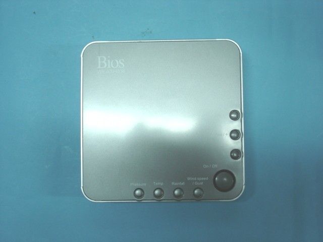
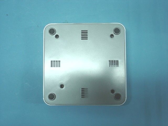
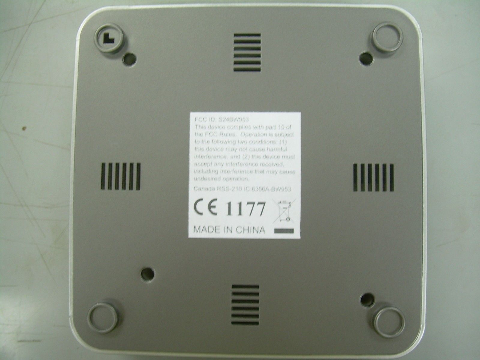
S24BW953HOME WEATHER STATION FOR TV VERSION
Imperial International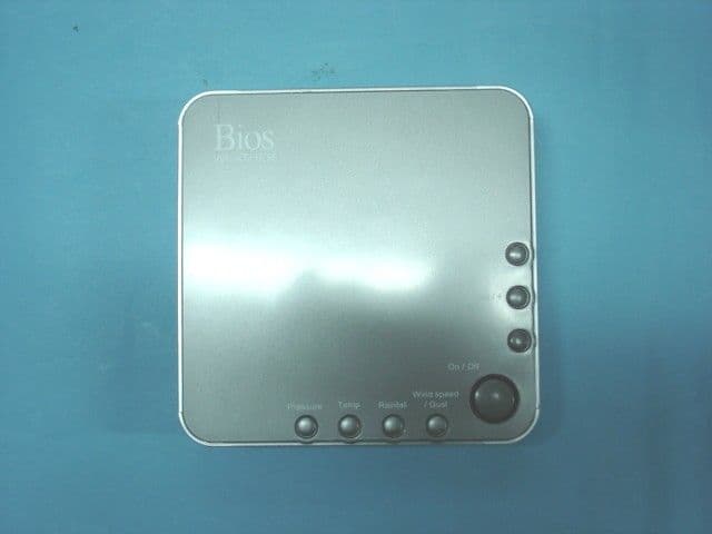
Click to zoom
Application Details
- Equipment Class
- JBP - Part 15 Class B Computing Device Peripheral
- Date of Grant
- Dec 11, 2006
- Application Purpose
- Original Equipment
- Date of Application
- Dec 11, 2006
- Equipment Note
- HOME WEATHER STATION FOR TV VERSION
- Company
- Imperial International
- Country
- United States
Documents & Files
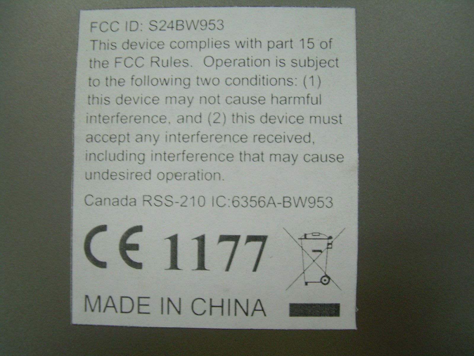
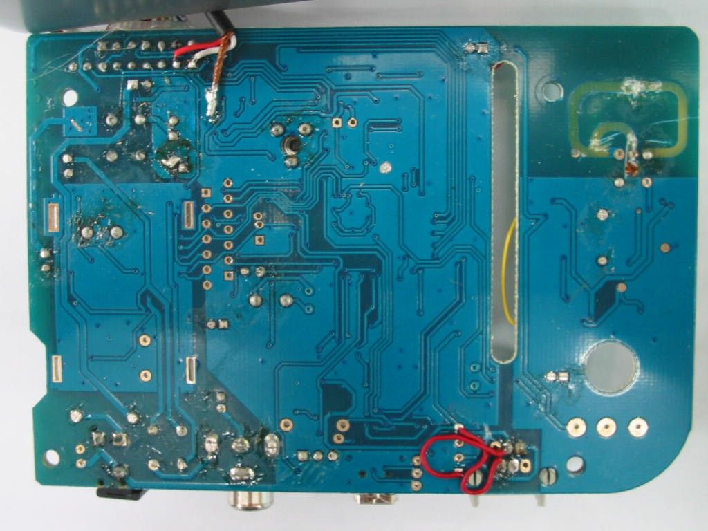
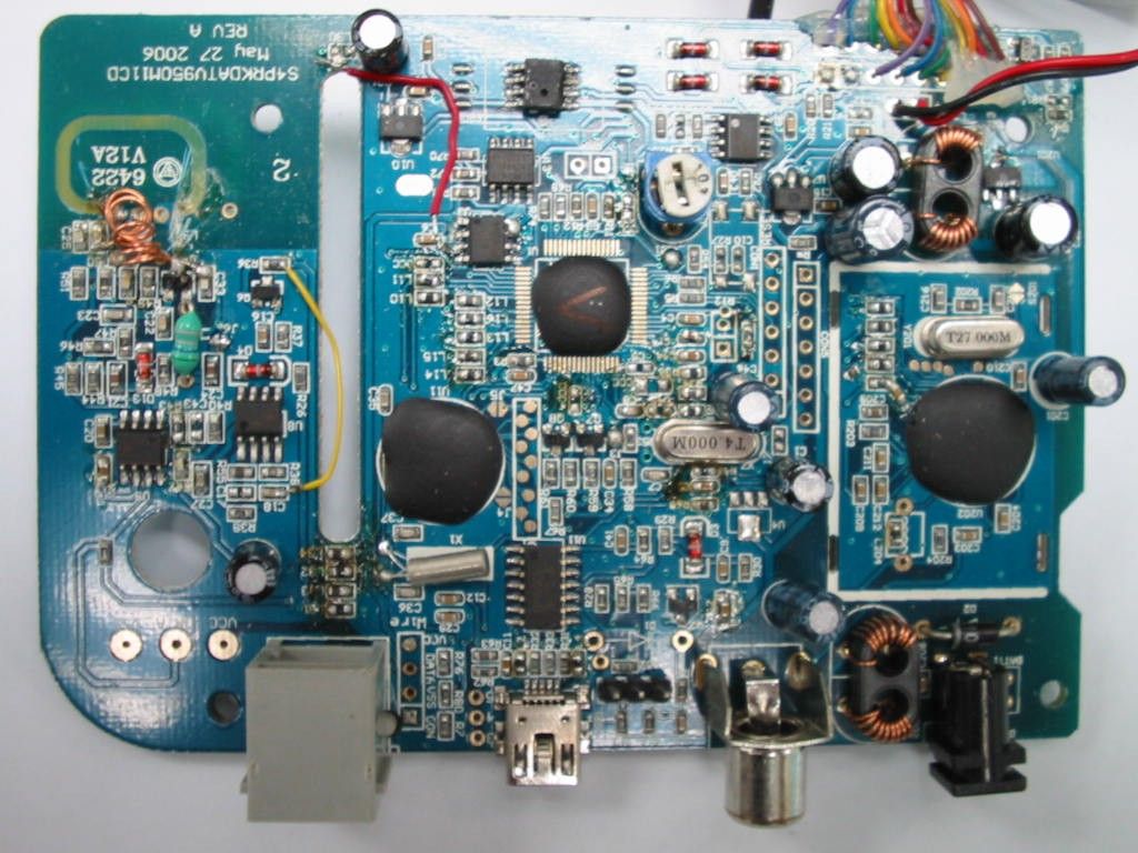
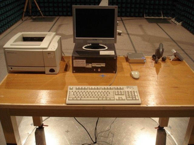
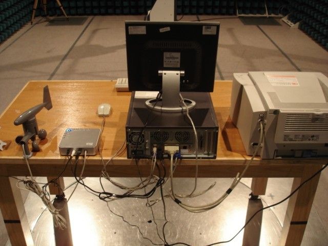
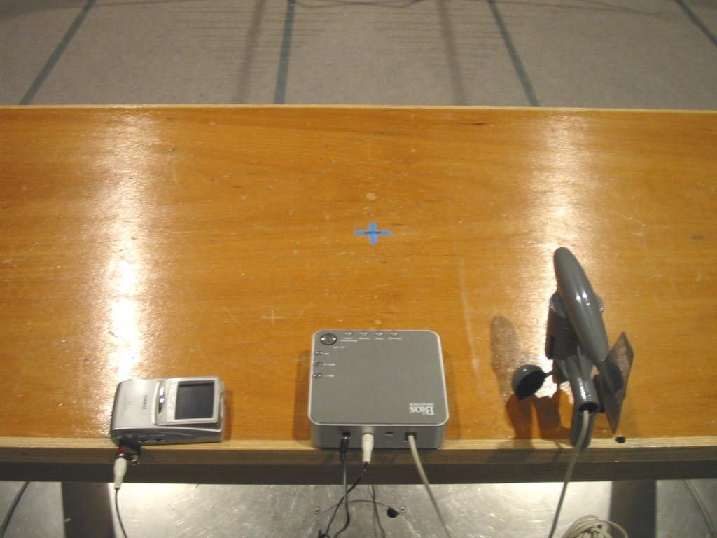
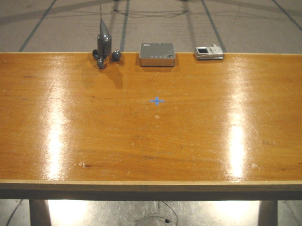
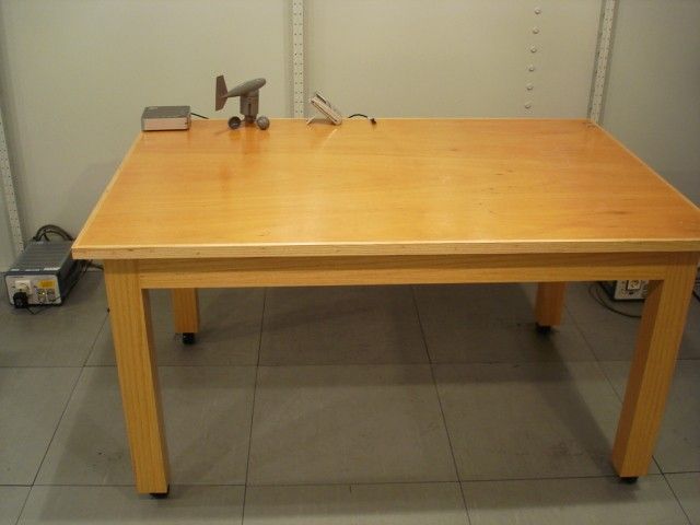
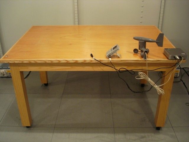
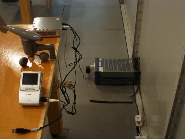
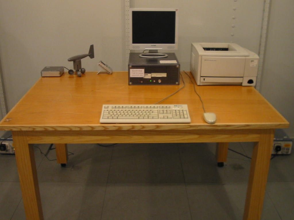
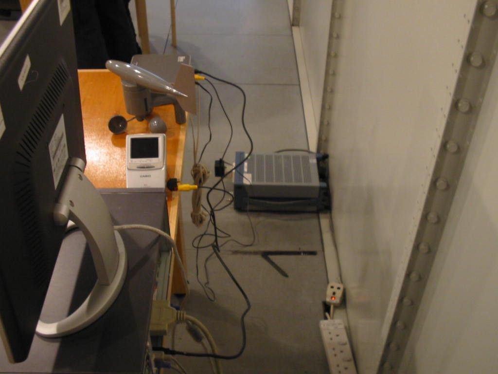
Document Text
Text extracted from the exhibit documents filed with the FCC. Open a document above to read the original.
Users Manual
Instruction Manual Home Weather Station for Television or PC Interface 2 2 3 3 3 4 4 4 4 5 7 7 8 8 9 9 9 9 10 11 11 11 11 11 12 12 13 13 13 15 16 17 20 26 26 27 27 Home Weather Station (HWS) for Television or PC Interface Instruction Manual Table of Contents 1. Introduction 2. Safety Notes 3. Weather Station Function and Features A. Features of the Indoor Receiver B. Features of the Thermometer-Transmitter Sensor C. Features of the Wind Sensor D. Features of the Rain Sensor 4. Mounting the Weather Station A. Indoor Receiver B. Wind Sensor C. Self-Emptying Rain Sensor D. Thermometer-Transmitter Sensor 5. Connecting the Sensors 6. Powering Up Your HWS for Television 7. Powering Up Your HWS for PC 8. Changing the Batteries in the Transmitter 9. Wireless Transmission 10. Wired Transmission 11. Button Breakdown (Quick Reference) 12. Setting the Indoor Receiver A. Time and Date B. Measurement Preferences 13. Minimum or Maximum Memory Reset 14. Rainfall Measurement Reset 15. Rain Gauge Maintenance 16. Trend Chart 17. Weather Forecasting 18. Wind Chill 19. Barometric Pressure Elevation of Major Cities in Canada Elevation of Major Cities in the US 20. Barometric Pressure Conversions 21. Troubleshooting 22. Product Specifications 23. Warranty 24. Resources to Look At 25. FCC Information This instruction manual is part of this product and should be kept in a safe place for future reference. It contains important information on setup and operation. 1. INTRODUCTION Thank you for purchasing the Bios Weather Home Weather Station (HWS) for Television or PC Interface. Developed with state of the art technology and digital electronics, this device provides instant readouts of the weather conditions around you. To understand how to properly install and program your weather station, please read this instruction manual carefully and keep it in a safe place. This product is intended for use at home. It has not been designed for scientific or commercial applications. IMPORTANT: Before setting up your HWS, you should first decide which interface you would like to use to view the weather readings. To set up the HWS for PC please refer to the Weather Analyzer Software Instruction Manual enclosed with this unit. To set up the HWS for television please continue on with this instruction manual. 2. SAFETY NOTES • Damage caused by failure to comply with this instruction manual will invalidate any warranty! The manufacturer and supplier will not be held liable for any damages due to failure to comply with this product! • In case of harm or damage to a person or property caused by improper handling or failure to comply with this instruction manual, the manufacturer and supplier cannot be held liable. • For reason of safety and operation, alteration to this device is strictly prohibited. • To operate the weather station, use only supplied adaptor and batteries of the recommended type. • Do not leave discharged batteries in the device as these may corrode and release chemicals that may damage the unit. • Do not dispose of new or used batteries in a fire as they may explode or release dangerous chemicals into the environment. • This product is not to be used for medical purposes or for public information. 2 3. FUNCTION AND FEATURES FOR TELEVISION AND PC A. Indoor Receiver • The indoor receiver measures the indoor temperature, humidity, atmospheric pressure and receives weather data from the thermometer-transmitter sensor, wind sensor, and rain gauge sensor. • Displays time and date • Displays indoor and outdoor temperature in Fahrenheit (°F) or Celsius (°C) -- user selectable • Displays indoor relative humidity (RH%) • Displays barometric (air) pressure reading in inches or millibars (mb) of mercury (inHg) -- user selectable • Displays cumulative rainfall data since last reset in inches (in) or centimeters (cm) – user selectable • Displays wind speed and gust in miles per hour (mph) or kilometers per hour (km) -- user selectable • Wind direction display with compass as well as numerical (e.g. 225°) and abbreviated characters (e.g. NE) • Wind chill temperature in Fahrenheit (°F) or Celsius (°C) -- user selectable • Displays weather forecast using weather icons (sunny, partly cloudy, cloudy or rainy) • Barometric trend chart in inches of mercury (inHg) or millibars (mb) -- user selectable • Indoor and outdoor temperature alarms that are set by the user (PC only) NOTE: To view the image of the screen on the PC please refer to the "Weather Analyzer Software Instruction Manual" enclosed with this unit (Section 7: Using the Weather Analyzer Software). B. Thermometer-Transmitter Sensor The data from the outdoor sensor is transmitted every 128 seconds to bring you the latest weather information which is displayed on the television screen or PC (updating information faster is prohibited by FCC criteria and would drastically reduce battery life). The thermometer-transmitter sensor connects to the wind and rain sensors via insulated cables, whereby power and weather information is transferred. The collected data is then transmitted by the thermometer-transmitter back to the indoor receiver wirelessly. Weather data is sent from the thermometer-transmitter sensor by radio signal at 433MHz (up to 60 yards / 60 meters, approximately 200 feet, in open space). The thermometer-transmitter sensor consists of the main unit, rain protection cover and base bracket. Power Adaptor: a special transmitter adaptor is available to supply power to the transmitter rather than using batteries. It is a perfect solution for your HWS during extremely cold temperatures in the winter months when batteries may cause problems. Please call 1-866-753-0181 for ordering information if not found at your local retailer. 3 Rain Sensor Wind Sensor Thermometer- Transmitter Sensor Television Screen 1. Date & Time 2. Wind Chill °C/°F (min/max) 3. Outdoor & Indoor Temperature °C/°F (min/max) 4. Barometric Pressure & Trend mb/inHg (min/max), over the last 24 hours 5. Rainf…
Text truncated - open the document above for the full version.
Operational Description
Operation Description for Home Weather Station for TV version The Home Weather Station for TV Version is meter for measure Wind Speed, Rainfall, Temperature and Pressure. It has 433MHz receiver to support the outdoor transmitter data and display on the TV and storage in PC. The IC U4 is responsible to display the reading on TV and U1 is a microcontroller with USB interface for PC connection. The Q4 and U8 is a receiver and amplify for receive outdoor transmitter radio signal and send to MCU.
Test Report
TEST REPORT Report No. : AG027053-001 Date : 2006 December 11 Page 1 of 12 FCC ID: S24BW953 This document shall not be reproduced except in full or with written approval by the laboratory. CMA Industrial Development Foundation Limited Room 1302, Yan Hing Centre, 9-13 Wong Chuk Yeung St.., Fo Tan, Shatin, Hong Kong. Tel: (852) 2698 8198 Fax: (852) 2695 4177 E-mail: [email protected] Web Site: http://www.cmatcl.com Application No. : LG219636(5) Client : Imperial International 2221 Niagara Falls Blvd. Niagara Falls, New York. 14304 Sample Description : One(1) submitted sample(s) stated to be Home Weather Station for TV version of Model No. DG950TV Radio Frequency : 433.920MHz Receiver Rating : AC 120V to DC 6V adaptor No. of submitted sample : One (1) piece(s) *** Date Received : 2006 August 30 Test Period : 2006 August 30 ñ 2006 October 03 Test Requested : FCC Part 15 Certification. Test Method : 47 CFR Part 15 (10-1-05 Edition) ANSI C63.4 ñ 2003 Test Result : See attached sheet(s) from page 2 to 12. Conclusion : The submitted sample was found to comply with requirement of FCC Part 15 Subpart B. For and on behalf of CMA Industrial Development Foundation Limited Authorized Signature : ____________________________________________________ Danny Chui Deputy Manager - EL. Division TEST REPORT Report No. : AG027053-001 Date : 2006 December 11 Page 2 of 12 FCC ID: S24BW953 This document shall not be reproduced except in full or with written approval by the laboratory. CMA Industrial Development Foundation Limited Room 1302, Yan Hing Centre, 9-13 Wong Chuk Yeung St.., Fo Tan, Shatin, Hong Kong. Tel: (852) 2698 8198 Fax: (852) 2695 4177 E-mail: [email protected] Web Site: http://www.cmatcl.com Table of Contents 1 General Information .............................................................................................................................3 1.1 General Description .....................................................................................................................3 1.2 Location of the test site ................................................................................................................4 1.3 List of measuring equipment ........................................................................................................5 2 Description of the radiated emission test .............................................................................................6 2.1 Test Procedure..............................................................................................................................6 2.2 Test Result....................................................................................................................................6 2.3 Radiated Emission Measurement Data ........................................................................................7 3 Description of the Line-conducted Test...............................................................................................9 3.1 Test Procedure..............................................................................................................................9 3.2 Test Result....................................................................................................................................9 3.3 Graph and Table of Conducted Emission Measurement Data .....................................................9 4 Photograph .........................................................................................................................................10 4.1 Photographs of the Test Setup for Radiated Emission and Conduction Emission ....................10 4.2 Photographs of the External and Internal Configurations of the EUT.......................................10 5 Supplementary document ...................................................................................................................11 5.1 Bandwidth ..................................................................................................................................11 5.2 Duty cycle ..................................................................................................................................11 5.3 Transmission time ......................................................................................................................11 6 Appendices .........................................................................................................................................12 TEST REPORT Report No. : AG027053-001 Date : 2006 December 11 Page 3 of 12 FCC ID: S24BW953 This document shall not be reproduced except in full or with written approval by the laboratory. CMA Industrial Development Foundation Limited Room 1302, Yan Hing Centre, 9-13 Wong Chuk Yeung St.., Fo Tan, Shatin, Hong Kong. Tel: (852) 2698 8198 Fax: (852) 2695 4177 E-mail: [email protected] Web Site: http://www.cmatcl.com 1 General Information 1.1 General Description The equipment under test (EUT) is a super regenerative receiver for Home Weather Station for TV version. It operates at 433.920MHz which is controlled by a LRC circuit. The EUT is powered by AC 120V to DC 6V adaptor. When it switched on, it can measure the Wind Speed, Rainfall, Temperature and Pressure. The build in receive can receive out door transmitter signal and display on TV or PC. There are single USB terminal for data storage in PC. The brief circuit description is listed as follows: - Q4, U9 and associated circuit act as RF receiver - X1, U11, Q7, Q8 and associated circuit act as LCD controller - Q5, U1, X7, U3, U13, Q1 and associated circuit act as controller - U7, U10, U2 and associated circuit act as voltage controller - U4, Y1 and associated circuit act as video controller TEST REPORT Report No. : AG027053-001 Date : 2006 December 11 Page 4 of 12 FCC ID: S24BW953 This document shall not be reproduced except in full or with written approval by the laboratory. CMA Industrial Development Foundation Limi…
Text truncated - open the document above for the full version.
Contact Information
Applicant
Hailey Burt(Sales Coordinator)
Test Firm
CMA Industrial Development Foundations LimitedStephen Lam
Technical Specifications
| # | Rule Parts | Frequency Range | Power Output |
|---|---|---|---|
| 1 | 15B | - | - |
Other Applications from Imperial International
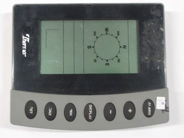
S24DG950R
Mar 09, 2005HOME WEATHER STATION
Equipment Class
CRR - Superregenerative Receiver