S2I-2966046/49MHz 10 Channel Cordless Phone w/ CID
Hui Zhou ADL Electronics Co. Ltd.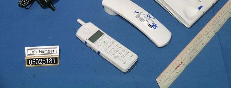
Click to zoom
Application Details
- Equipment Class
- ETS - Part 15 Cordless Telephone System
- Date of Grant
- Jun 21, 2005
- Application Purpose
- Original Equipment
- Date of Application
- Jun 21, 2005
- Equipment Note
- 46/49MHz 10 Channel Cordless Phone w/ CID
- Frequency Range
- 49.67000000 - 49.99000000
- Country
- China
Documents & Files
Document Text
Text extracted from the exhibit documents filed with the FCC. Open a document above to read the original.
Users Manual
INTRODUCTION Both of your base unit and handset can store and display 48 Caller ID with 16 digits, Record up to 10 dialed numbers with 28 digits; 10 phonebooks; LCD screen with backlight. To get the most from your new phone, we suggest that you take a few minutes right now to read through this user’s guide. Notice:Your Caller ID phone stores and displays spe- cific information provided by your local telephone company, to subscribers of Caller ID or similar caller identification services. You must subscribe to one of these services in order to use this unit. WARNING: TO PREVENT FIRE OR ELECTRICAL SHOCK HAZARD,DO NOT EXPOSE THIS PRODUCT TO RAIN OR MOISTURE. BEFORE YOU BEGIN PARTS CHECKLIST Make sure your package includes the items: 1.Base unit 2.Handset 3.Corded Handset 4.Handset Coiled Cord 5.Handset Battery 6.Charger 7.Telephone Line Cord 8. AC Power Supply (Two pieces) INSTALLING THE PHONE 1.Remove the battery compartment door of handset. 2.Insert battery pack and connect the cord into the jack inside the handset. 3.Put the compartment door back on. 4.Place the handset in the charger. 5.Plug the power supply cord into AC outlet and the other end into the power jack on the Charger. 6.Pull the antenna full out of Base unit. 7.Plug the power supply cord into AC outlet and the other end into the power jack on the Base unit. Power is on when the Power LED is light up. Note: Place the handset in the Charger to charge for 10 hours prior to first use. 8.Plug one end of the telephone line cord into the modular wall phone jack and the other end into the jack on the base marked TEL LINE. Notice: The phone automatically defaults to tone dialing. To change to pulse dialing, see “Tone/ Pulse Dialing”. If you don’t know which type of service you have, check with the phone company. 9.Keep the Base unit away from the jammer (Such as television, computer, microwave oven, refrig- erator and so on) and place it in the center of the using area. In order to the best using, pull the antenna full out of Base unit. Notice: Use the power supply in the package that came with this unit. Using other power supplies may damage the unit. IMPORTANT: When there is some noise in the handset speaker, pull the handset antenna out. LCD Display Icons in the base unit and the handset: 1. :IN use 2. 00 :Number of calls 3. :Battery full (handset) 4. :Battery flat (handset) 5. New call # :New calls 6. Out :Dialing calls 7. :Phonebook 8. Rep :Repeating Records 9. 00:00 :(Hour: Minute) 10. 1-10 : Date ( handset) 11. 1 M 10 D :Date ( base unit) LCD Display Icons in the charger 1. :The finger of the clock 2. :The alarm clock and the time 3. :Set the time 4. :Set the alarm clock 5. :Set the contrast of the LCD 6. :Setup key 7. :Adjust key Date and Time Setting (just in base unit) a.Press down the “Set Time” key for 3 sec- onds to enter the Date and Time Setting when base unit is on hook. b.Set the hour and press the “Set Time” key, then set the minute and press the “Set Time” key. Continuous set the month and the date. c.Press the “<” key to increase and the “>” key to degression when setting. d. The time of the handset will keep with the base unit. LCD Contrast Setting (both base unit and handset) a.Press down the “ Store/Menu” key for 3 seconds to enter setting state when base unit is on hook. b.Press the “Store/Menu” key continuous until “LCD 3” appears. c.Press the “<” or “>” key to set the contrast of the LCD. d.Press the “Store/ Menu” key to comfirm. e.Press “Exit” key to exit. Long-distance Code Setting (base unit) a.Press down the “Store/ Menu” key for 3 seconds to enter setting state when base unit is on hook. b.Press the “*” key continuous until “LO CODE” appears. c.Press a digital key to enter a number. Press the “Del” key if wrong. d.Press the “Store/ Menu” key to comfirm. e. Press “Exit” key to exit. Note: The Caller ID number will add the long-distance code when it is over 8 digits.after setting the code. Example: If long-distance code is 0 and the Caller ID is 13751588116, then the number will be displayed as 01375158816. Local Area Code Setting (base unit) a.Press down the “Store/ Menu” key for 3 seconds to enter setting state when base unit is on hook. b.Press the “*” key continuous until “CODE- ” appears. c .Enter code number less than 4 digits. Press the “Del” key if wrong. d.Press the “Store/ Menu” key to comfirm. e. Press “Exit” key to exit. Note: The local area code will be deleted if the Caller ID number contains it after setting the code. Example: If the code is 752 and the Caller ID is 7522619913, then the number will be displayed as 2619913 Ring Selection (both of base unit and handset) a.Press the “Volume” key until “RING” appears. b.Press the “<” or “>” key to select the ring. c.Press the “Exit” key to exit. d. Ring is off when handset select “0”, and “RING OFF” appears. Alarm Clock Setting (handset) 1.Press down the “Store/ Menu” key for 3 sec- onds to enter setting state when handset is on hook. “Alarm Clock” appears. 2.Press the “<” or “>” key to select on or off. 3.Press the “Store/ Menu” key. 4.Alarm clock is off when select off. 5.Alarm clock is on when select on. Press the “<” or “>” key to select hour and press the “Store/ Menu” key, then press the “<” or “>” key to select minute and press the “Store/ Menu” key. 6. Press the “Exit” key to exit. Auto Talk mode Setting (handset) 1.Press down the “Store/ Menu”key for 3 sec- onds to enter setting state when handset is on hook. 2.Press the “*”key continuous until “AUTO ON” appears. 3.Press the “<” or “>” key to select on or off. 4.The function is off when select off; otherwise, it is on. When the function is on, you can talk after pick handset up without press any key; otherwise, press any key to get the talk. 5.Press the “Store/ Menu” key. 6. Press the “Exit” key to exit. Charger Clock Setting Time Setting 1.Press down the “Set up” key for 3 seconds until “ ” flicker. 2.Press the “Adjust” key to set hour and press the “Set up”key; then press the “Adjus…
Text truncated - open the document above for the full version.
Users Manual
Handset calls base unit 1.Press the “Intercom” key on the handset when on hook. 2.Base unit rings. 3.Press the “Speaker” key or pick up the corded handset to talk with the handset. 4. Get on hook after the call. If no answer, the state will cancel. Notice: If there was a call while intercom mode the unit will be auto exit the intercom mode. Base unit transfer a call to handset When user answer a call with base unit: 1.Press the “Intercom” key on the base. 2.Press the handset number (no needs if just 1 handset) or press “*” key to transfer to all handsets. 3.Handsets ring. 4.Press any key to answer the call. 5.The first answering handset can get the call. 6.The call will transfer back to the base and both the base and handsets will ring if no handset answers the call in a minute; The call will end after another minute if no answer. Handset transfer to the base or an- other handset 1.Press the “Intercom” key on the handset. 2.Press the number key to transfer to base or other handset (0: base/ 2,3,4¡-: another hand- set/ *: all handsets). The base or the transfer which transfer to will ring, and then answer the call. 3. The call will transfer back to the first handset and both the base and handsets will ring if no answer in a minute; The call will end after an- other minute if no answer. CALLER ID This phone receives and displays information trans- mitted by you local phone company is running with FSK or DTMF system. The phone can store up to 48 calls for later review. While you have a Caller ID, the display will show as follow. Handset: Base unit: Notice: In order to use the Caller ID functions with this phone, you must subscribe to Number Caller ID Service. Reviewing Calls: 1.Press the “<” or “>” key to get into CID mode when on hook. 2.You can press number keys to add numbers or press the “#” key to delete numbers. 3.Press the “<” key to scroll from the most re- cent to the oldest, otherwise press the “>” key. You can review up to 48 calls (16 digits). 4.If the CID number is over 15digits on the base or over12 digits on the handset, press the “*” key to scroll. 5. Press the “Exit” key to exit CID mode. Deleting the CID Records: 1.Press “<” or “>” to scroll the desired record. 2.Press “Del”, LCD displays “DEL ONE”, and then press “Del” again to delete the record. 3. Press down “Del” until a “Beep” sound emitted, LCD displays “DEL ALL”, and then press “Del” again to delete all the records. Dialing a Caller ID Number: 1.Press “<” or “>” to scroll the desired record. 2.Press “Dial/ Set time” to dial the number. 3. Press “Talk” on the handset or press “Speaker”/ pick up the handset on the base. The number is dialed out automatically. Transferring CID Records to Memory 1.Press “<” or “>” to scroll the desired record.] 2. Press “Store”, and then press number key (0~ 9) to select a desired memory location. After a “Beep”, LCD display “ rECode”. Review/ Delete/ Redial/ Store Di- aled Number 1.Press “Redial/ Pause” to get into Reviewing Di- aled Number mode when on hook. 2.Press “Redial/ Pause” continuous to review di- aled number. You can review the last 10 num- bers (28 digits). 3.Press “*” to scroll the record to review the num- ber and the time. 4. Other operation is the same to review CID operations. PHONEBOOK MEMORY Both the base and handset can store up to 10 16-digit numbers in memory. Storing a Number in Memory 1.Press the numbers and press “Store/Menu” when on hook. 2. Press 0-9 key to select a desired memory. locationAfter a “Beep”, LCD display “rECord”. 3. Press the “Redial/Pause” key to insert a pause in a storing number. Reviewing the Phonebook Memory Press “Store/Menu” to get into the mode and press “<” or “>” to review the number stored in the memory. Deleting The Stored Number Press “<” or “>” to scroll the desired record. And then press “Del” twice to delete the number. Dialing The Stored Number 1. Press “<” or “>” to scroll the desired record. And then press “Redial” or get off hook. 2. Press “Store/Menu” and then press the memory location number when off hook. Dialing Some Memory at the Same Time: This function is set for the users who always make long-distance calls. You can dial some memory numbers at the same time just accord- ing to the explanation. Example: The type of long-distance number location of the memory Area number 755 07 Long-distance number 008 Phone number 811309 1.Get off hook. 2.Press “Store”, and then press “7”. 3.Press “Store”, and then press “8” after hearing a tone. 4.Press “Store”, and then press “9” after hearing a tone. Notice: Before you press another location number, you must wait for the end of the tone. Mute To prevent the person you are speaking from hearing you while on a call. 1. Press “Mute”, LCD display “MUTE”, the phone on mute. 2. Press “Mute” again to cancel mute mode. Or press “Speaker” to switch handset or speaker mode. Battery Indicator 1.The battery flat icon will flash when power is low and handset is on hook. 2.The battery flat icon will flash and a “Beep” sound emitted continuous when power is low and handset is off hook. 3.Please put the handset on the charger to charge your battery. Notice: The call will be ending if the battery power is low. Please charge the battery no less than 10 min- utes before you use again. Alarm for over-distance If you heard a brief and continuous “Beep” when hand- set is in use, it means you have out of the using range or the antenna is not pull out. Please close up to the base or pull out the antenna, or the base will end the call after 20 seconds. Auto-transfer Function When Power Off If suddenly the power is off when handset is in use, the LCD of base will be show “OF”; the base will transfer to holding mode (the other side will hear the music), pick up the corded handset in 2 minutes, the call will go on, otherwise, the call will end. General Produce Care To keep your telephone working and looking good, follow these guidelines: DO NOT expose to direct sunlight or moisture. Avoid dropping and other ro…
Text truncated - open the document above for the full version.
Block Diagram
DC 9V regulator speech circuitry POWER Q20 Q13,Q14,Q25,Q26 RESET memorizer handset KEYBOARD Q17?Q18 IC5 MIC ECLK ,DI MUTE RESET MCU electron- handfree LCD EM78806 switch MIC X3 Crystal 32.768kHz RINGER ring detect RF module U3 Q35 U8 HS SPEAKER DP /HKS interface SWITCH DTMF circuitD3,D9,D10,D11 Q3?Q4, Q19 amplifier Q11 LINE JACK Handfree amplifier HANDFREE Q6?Q7 SPEAKER Q5 29660 block drawing (base unit) memorizer POWER LCD BATTERY U1 CHARGER ZD1,D13 CHG MCU crystal KEYBOARD X3 32.768kHz EM78805 RINGER Q3,Q4,BZ1 RF module RECEIVER MIC 2 U3 spk Antenna 29660/26760 BLOCK DRAWING (HANDSET UNIT)
External Photos
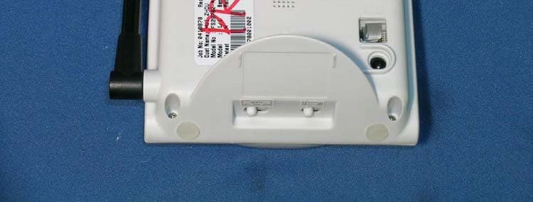
External photos FCC ID: S2I-29660 External photos FCC ID: S2I-29660
ID Label/Location Info
FS29660XXX-A S/NO:YNNNNNNN 4515DY FS29660CE/GE LABEL ARTWORK Base unit Charger ATLINKS Model No.:FS29660XXX-A Cordless telephone Use only Atlinks power supply Type No.:G090020D22 MADE IN CHINA ATLINKS USA MODEL: FS29660XXX-A CORDLESS TELEPHONE USE ONLY ATLINKS POWER SUPPLY COMPLIES WITH 47 CPR PART IS REQUIREMENT XXXXXXXXXXXXX FCC ID: S2I-29660 THIS DEVICE COMPLIES WITH PART I5 OF THE FCC RULES. OPERATION IS SUBJECT TO THE FOLLOWING TWO CONDITIONS (1)THIS DEVICE MAY NOT CAUSE HARMFUL INTERFERENCE . AND(2)THIS DEVICE MUST ACCEPT ANY INTERFERENCE RECEIVED, INCLUDING INTERFERENCE THAT MAY CAUSE UNDESIRED OPERATION. PRIVACY OF COMMUNICATIONS MAY NOT BE ENSURED WHEN USING THIS PHONE. REG. NO. US: - MADE IN CHINA MADE IN CHINA The battery compartment door 19mm 7mm 49mm 14mm 60mm 40mm 12mm Handset M o d e l : F S 2 9 6 6 0 X X X - A S / N O : Y N N N N N N N C A U T I O N : T O R E D U C E T H E R I S K O R P E R S O N A L D I A R Y , U S E O N L Y B A T T E R Y L I S T E D I N U S E R B O O K . F C C I D : S 2 I - 2 9 6 6 0 M A D E I N C H I N A 3 4 . 5 m m 17mm 4 5 1 5 D Y 4 m m 1 2 m m 1 8 . 5 m m 34.5mm
Internal Photos
Internal photos FCC ID: S2I-29660 Base assembly Base Main PCB comp side (View 1) Internal photos FCC ID: S2I-29660 Base Main PCB comp side (View 2) Base Main PCB solder side Internal photos FCC ID: S2I-29660 Base Keypad front side Base Keypad rear side Internal photos FCC ID: S2I-29660 Base LCD display front side Base LCD display rear side Internal photos FCC ID: S2I-29660 Handset assembly Handset Main PCB comp side Internal photos FCC ID: S2I-29660 Handset Main PCB solder side Handset Main PCB display comp side Internal photos FCC ID: S2I-29660 Handset Main PCB display solder side
Operational Description
FS29660 Circuit Description The following circuit description is for model FS29660 and which base on the circuit diagram and block diagram. 1. RECEIVING PATH (HANDSET) After the RF signal is pick up by the solid-wire antenna, the receiving path is Established by the SAW duplexer after and input to tuning amplifier Q4 before output to COMBO IC 1 st mixer. a. Mixer Mixer is included in COMBO U3.Local Oscillator (LO) is controlled through External coil T3.The first IF (10.7MHZ) is filtered by ceramic filter CF1 b. IF amplifier IF amplifier is built in U3.Amplifier IF is filtered again by a ceramic filter CF2, Then input to FM demodulator also inside COMBO. c. FM demodulator and expander The IF demodulated by quadrate coil COMBO, then the recovered audio is input to the expander for de-emphasis, before output to the handset speaker though audio amplifier. 2. TRANSMITTING PATH (HANDSET) The transmitting path is established by below sections. a. Microphone amplifier and compressor Audio frequency picked up by handset microphone is amplified by internal mic Amplifier of U3, the input to compressor for pre-emPhasis, before input to the modulator.(Tx VCO). b. Modulator and Tx VCO The transmit PLL is internal at U3 and the transmit VCO is controlled by external coil T4. Both audio and data signal input to the transmit VCO will cause a frequency modulation progress. C. RF power amplifier FM signal is amplifier by Q8 and fit to the telescopic antenna through SAW duplexer . 1.RECEIVING PATH (BASE) The receiving path is established by below sections. a . Low Noise Amplifier (LNA) FM signal pick up by the rubber type antenna is filtered by the SAW duplexer, and input to tuning amplifier Q201 before output to COMBO IC 1 st mixer. b. Mixer Mixer is include in COMBO U201.Local Oscillator (LO) is controlled through external coil T2.The first IF (10.7MHZ) is filtered by a ceramic filter CF201. C. IF amplifier IF amplifier is built in U201. Amplified IF is filtered again by a ceramic filter CF1, then input to FM demodulator also inside COMBO. d. FM demodulator and expander The IF demodulated by quadrate coil COMBO, then the recovered audio is input to the expander for de-emphasis, before output to the final AF amplifier for speech circuitry and line interfacing. 2. TRANSMITTING PATH The transmitting path is established by below sections. a. Mic amplifier and compressor Audio frequency input from the line interface is amplified by internal mic amplifier of U201, then input to compressor for pre-emphasis, before input to the modulator (TX VCO) b. Modulator and TX VCO The transmit PLL is internal at U201 and the transmit VCO is controlled by external coil T203. Both audio and data signal input to the transmit VCO will cause a frequency modulation progress. C.RF power amplifier FM signal is amplifier by Q205 and fit to the soft-wire spring type antenna through SAW duplexer. 3.TELEPHONE INTERFACE The telephone line interface circuit and speech circuitry is established by below sections. a. Audio power amplifier Q13,Q14& Q25,Q26 are built as power amplifier, according to high current output requirement for speech circuitry. b. Line control Q3 & Q19 is the opening for line seizure, which is controlled by Q4. c. Ring detect circuit Q35 is for detecting the ring signal. d. Caller ID The Caller ID signal pass through C73, C74, R116, R117 to MCU for decoding. 46/49 Frequency Table Handset Unit (MHz) BASE UNIT(MHz) CHANNEL TX Freq RX Freq TX Freq RX Freq HS TX VCO Base TX VCD 1 49.670 46.610 46.610 49.670 49.670 46.610 2 49.854 46.630 46.630 49.845 49.845 46.630 3 49.860 46.670 46.670 49.860 49.860 46.670 4 49.770 46.710 46.710 49.770 49.770 46.710 5 49.875 46.730 46.730 49.875 49.875 46.730 6 49.830 46.770 46.770 49.830 49.830 46.770 7 49.890 46.830 46.830 49.890 49.890 46.830 8 49.930 46.870 46.870 49.930 49.930 46.870 9 49.990 46.930 46.930 49.990 49.990 46.930 10 49.970 46.970 46.970 49.970 49.970 46.970
Schematics
IN29660BS_ES6_FTMS.sch-1 - Sat Feb 05 16:57:36 2005 IN29660BS_ES6_FTMS.sch-2 - Sat Feb 05 16:57:37 2005 HW29660BS_CPU_MP.sch-1 - Tue Feb 22 14:54:13 2005
Test Report
• The test results reported in this test report shall refer only to the sample actually tested and shall not refer or be deemed to refer to bulk from which such a sample may be said to have been obtained. • This report shall not be reproduced except in full without prior authorization from Intertek Testing Services Hong Kong Limited. • For Terms And Conditions of the services, it can be provided upon request. • The evaluation data of the report will be kept for 3 years from the date of issuance. Intertek Testing Services Hong Kong Ltd. 2/F., Garment Centre, 576 Castle Peak Road, Kowloon, Hong Kong. Tel: (852) 2173 8888 Fax: (852) 2741 1693 Website: www.hk.intertek-etlsemko.com Hui Zhou ADL Electronics Co., Ltd. Application For Certification 46MHz/49MHz 10 Channel Analog Modulation Cordless Phone with Caller ID (FCC ID: S2I-29660) 05025181 TL/ Ann Choy March 2, 2005 INTERTEK TESTING SERVICES FCC ID: S2I-29660 i LIST OF EXHIBITS INTRODUCTION EXHIBIT 1 : General Description EXHIBIT 2 : System Test Configuration EXHIBIT 3 : Emission Results EXHIBIT 4 : Frequency Deviation EXHIBIT 5 : Operating Bandwidth EXHIBIT 6 : Equipment Photographs EXHIBIT 7 : Product Labelling EXHIBIT 8 : Technical Specifications EXHIBIT 9 : Instruction Manual EXHIBIT 10 : Security Code Information INTERTEK TESTING SERVICES FCC ID: S2I-29660 ii MEASUREMENT/TECHNICAL REPORT Hui Zhou ADL Electronics Co., Ltd. - MODEL: FS29660XXX-A, H29660XXX-A, EX29660XXX-A, TW29660XXX-A, IN29660XXX-A, SB29660XXX-A FCC ID: S2I-29660 This report concerns (check one:) Original Grant X Class II Change Equipment Type: ETS - Cordless Telephone System Deferred grant requested per 47 CFR 0.457(d)(1)(ii)? Yes No X If yes, defer until: date Company Name agrees to notify the Commission by: date of the intended date of announcement of the product so that the grant can be issued on that date. Transition Rules Request per 15.37? Yes No X If no, assumed Part 15, Subpart C for intentional radiator - the new 47 CFR [12-08-03 Edition] provision. Report prepared by: Tommy Leung Intertek Testing Services. 2/F., Garment Centre, 576 Castle Peak Road, Kowloon, Hong Kong. Phone: 852-2173-8538 Fax: 852-2741-1693 INTERTEK TESTING SERVICES FCC ID: S2I-29660 iii List of attached file Exhibit type File Description filename Test Report Test Report report.doc Operation Description Technical Description descri.pdf Test Setup Photo Radiated Emission for Base config photos.doc Test Setup Photo Radiated Emission for Handset config photos.doc Test Report Conducted Emission Test Result conduct.pdf Test Setup Photo Conducted Emission config photos.doc Test Report Base Bandwidth Plot bsbw.pdf Test Report Handset Bandwidth Plot hsbw.pdf External Photo External Photo external photos.doc Internal Photo Internal Photo internal photos.doc Block Diagram Block Diagram block.pdf Schematics Circuit Diagram circuit.pdf ID Label/Location Label Artwork and Location label.pdf User Manual User Manual manual.pdf User Manual FCC Information fcc information.pdf INTERTEK TESTING SERVICES FCC ID: S2I-29660 iv Table of Contents 1.0 General Description ....................................................................................................... 2 1.1 Product Description ................................................................................................. 2 1.2 Related Submittal(s) Grants ................................................................................... 3 1.3 Test Methodology.................................................................................................... 3 1.4 Test Facility ............................................................................................................. 3 2.0 System Test Configuration ...................................................................................... 5 2.1 Justification ............................................................................................................. 5 2.2 EUT Exercising Software ......................................................................................... 5 2.3 Support Equipment List and Description....................................................................... 6 2.4 Measurement Uncertainty ....................................................................................... 7 2.5 Equipment Modification ........................................................................................... 7 3.0 Emission Results ..................................................................................................... 9 3.1 Field Strength Calculation ...................................................................................... 10 3.2 Radiated Emission Configuration Photograph - Base Unit......................................... 11 3.3 Radiated Emission Data - Base Unit .......................................................................... 12 3.4 Radiated Emission Configuration Photograph - Handset........................................... 14 3.5 Radiated Emission Data - Handset ........................................................................ 15 3.6 Line Conducted Configuration Photograph - Base Unit........................................... 17 3.7 Line Conducted Configuration Data - Base Unit ..................................................... 18 4.0 Frequency Deviation .............................................................................................. 21 4.1 Base Unit .............................................................................................................. 22 4.2 Handset ................................................................................................................ 24 5.0 Operating Bandwidth ............................................................................................. 27 5.1 Base Unit .............................................................................................................. 28 5.2 Handset ............................................…
Text truncated - open the document above for the full version.
Test Report
Report No.:05025181 Talk Mode Ctrl No.:N/A PAGE 1 Tested By:Hong, Report No.:05025181 Scan Settings (1 Range) |--------- Frequencies -----------||----------- Receiver Settings ------------| Start Stop Step IF BW Detector M-Time Atten Preamp OpRge 150k 30M 5k 10k PK+AV 10ms AUTO LN OFF 60dB Final Measurement: x QP / + AV Meas Time: 1 s Subranges: 16 Acc Margin: 20dB Transducer No. Start Stop Name 21 9k 30M EW0698 0 10 20 30 40 50 60 70 80 90 dBuV 100 0.15 MHz 30110 F15Q F15A Report No.:05025181 Talk Mode Ctrl No.:N/A Tested By:Hong, Report No.:05025181 Scan Settings (1 Range) |--------- Frequencies -----------||----------- Receiver Settings ------------| Start Stop Step IF BW Detector M-Time Atten Preamp OpRge 150k 30M 5k 10k PK+AV 10ms AUTO LN OFF 60dB Final Measurement Results: no Results
Test Setup Photos
The Worst Case Configuration Photographs FCC ID: S2I-29660 Radiated Emission – Base Front View Rear View The Worst Case Configuration Photographs FCC ID: S2I-29660 Radiated Emission – Handset Front View Rear View The Worst Case Configuration Photographs FCC ID: S2I-29660 Conducted Emission Front View Rear View The Worst Case Configuration Photographs FCC ID: S2I-29660 Conducted Emission Side View
Contact Information
Applicant
Zhang Chang Fu(R&D Manager)
Technical Contact
Intertek Testing Services Hong Kong Ltd.Tommy Leung
[email protected]852-2173-8538
2/F., Garment Centre, · Kowloon · Hong Kong
Non-Technical Contact
Intertek Testing Services Hong Kong Ltd.Tommy Leung
[email protected]852-2173-8538
Test Firm
Intertek Testing Services Hong KongBilly Chow
Technical Specifications
| # | Rule Parts | Frequency Range | Power Output |
|---|---|---|---|
| 2 | 15C | 49.67 MHz - 49.99 MHz | - |
Other Applications from Hui Zhou ADL Electronics Co. Ltd.
S2I-26760
Jun 21, 200546/49Mhz 10 Channel Cordless phone w/ CID
Equipment Class
ETS - Part 15 Cordless Telephone System