S3YO2XMTri-Band GSM Mobile Phone
FL Telecom ApS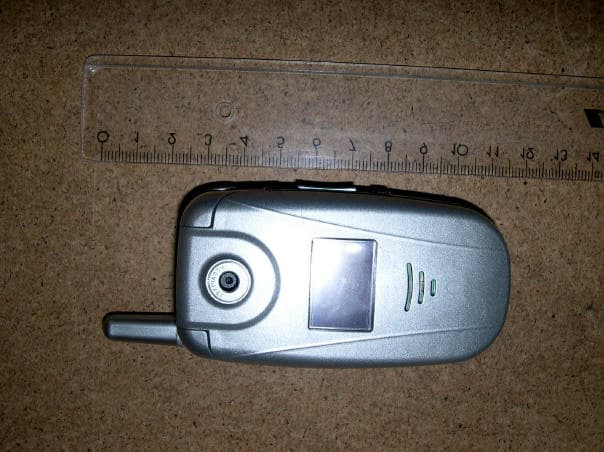
Click to zoom
Application Details
- Equipment Class
- PCE - PCS Licensed Transmitter held to ear
- Date of Grant
- Jun 05, 2005
- Application Purpose
- Original Equipment
- Date of Application
- Jun 05, 2005
- Equipment Note
- Tri-Band GSM Mobile Phone
- Frequency Range
- 1850.20000000 - 1909.80000000
- Company
- FL Telecom ApS
- Country
- Denmark
Documents & Files
Document Text
Text extracted from the exhibit documents filed with the FCC. Open a document above to read the original.
Users Manual
Doc. name:E22 User Guide Pages: 72 - 1 - Doc. type:Doc. type:Project DocumentationProject Documentation Date: 2005-06-02 E22 Doc. no: Doc. type: Doc. no: Doc. type: 1409000114090001 Project Documentation 14090001 Project Documentation Revision: 1.1 Dept.:Dept.:Sales DepartmentSales Department Initials: DRE File name: \\Fileserver\departments\Admin\Technical Program Management\Technical Writer\FLT_User_Guides\Customers\File name: \\Fileserver\departments\Admin\Technical Program Management\Technical Writer\FLT_User_Guides\Customers\ Dept.: File name: \\Fileserver\departments\Admin\Technical Program Management\Technical Writer\FLT_User_Guides\Customers\ Dept.:Dept.: File name: \\Fileserver\departments\Admin\Technical Program Management\Technical Writer\FLT_User_Guides\Customers\ Dept.:Sales Department File name: \\Fileserver\departments\Admin\Technical Program Management\Technical Writer\FLT_User_Guides\Customers\ Sales DepartmentSales Department File name: \\Fileserver\departments\Admin\Technical Program Management\Technical Writer\FLT_User_Guides\Customers\ Sales Department O2_England\O2_E22O2_England\O2_E22 E22 User Guide E22 02.05.2005 - Revision notes: This document is based on InDesign document E22_textonly, revision 2.5.3 and replaces previous document, based on revision 2.5.2 * Only change from 2.5.2 is revision of SAR information, including the FCC Safety Information for RF exposure text FL Telecom ApS, Niels Jernes Vej 8b, 9220 Aalborg East, Denmark, +45 96355500FL Telecom ApS, Niels Jernes Vej 8b, 9220 Aalborg East, Denmark, +45 96355500 QT-00150, Rev. 2 The content of this document is confi dential O2 XM (FLT E22) User Guide Text draft version 1.0 - Revision 2.5.3 - Text only Based on sw release 231.17.000 June 2nd, 2005/DRE Notes XI READ ME FIRST We strongly recommend that you read this document in full before using your O2 XM cellular phone as it contains important information regarding your safety, the safety of others and your legal rights WARNINGS Radiation. Mobile phones are low power radio transmitters. When the phone is on, it emits microwave radiation from the antenna. This radiation is absorbed by the body (SAR) and concerns has been raised that absorption poses a potential risk. Although no conclusive scientifi c evidence of any such risk exists at this point, we recommend that you seek information about and comply with the instructions regarding the safe use of cellular phones given by the health authorities in your country or area. O2 XM mobile phones are compliant with the safety guidelines issued by the International Commission on Non-Ionising Radiation Protection (ICNIRP Guidelines 1998). SAR value is stated in the “Technical Data” paragraph. See also FCC Safety Information for RF exposure below. Interference. The use of mobile phones may in some cases interfere with inadequately shielded electronic devices, causing malfunction. Therefore your phone should be switched off or in “Flight mode” during in air travel and in hospital or care facilities. Switch off your phone if you are in a blasting area, i.e. a quarry or construction site, as blasting often involves the use of HF equipment and your phone may interfere with this. Medical devices. If you use a hearing aid or depend on a pacemaker or other medical device, you should contact the manufacturer of the equipment or your physician before using a mobile phone. Always keep your mobile phone at a minimum distance of six inches from a pacemaker, and never carry a mobile phone in your breast pocket. Turn the phone off immediately if you suspect interference. Health. Recent reports suggest that excessive use of SMS may lead to fatigue or wear in fi nger joints. Concerns regarding SMS addiction or depressive conditions have also been voiced. We recommend that you use this function moderately to avoid health risks. Corrosion. Do not attempt to disassemble the phone or battery, as potential health risks are involved. Unauthorized disassembly will void the warranty. No user serviceable parts inside. Avoid skin contact with liquid from a broken battery. Harmful if swallowed. Seek physician immediately if exposed to battery liquids. Choking. Keep away from children as the SIM card or other small parts presents a choking hazard. Ear safety. The earpiece may produce very high sounds when you receive a call. To protect yourself from acoustic shock, newer hold your phone close to the ear unless you are engaged in telecom conversation. Never let children play with a turned-on cell phone. Combustibles & explosives. Although rare, internal micro sparks during operation can pose an ignition risk. Switch off your phone near areas with combustible vapours and do not store your phone together with Notes XII fl ammable or explosive materials. Battery safety. Never short-circuit the battery. Keep away from jewellery and metal objects. The battery may present a fi re or chemical burn hazard if mistreated. Do not disassemble or crush. Do not expose the battery to heat above 100 °C (212 °F) or incinerate it. Use only original batteries, supplied by O2. Use of non-original batteries or charger may cause fi re or explosion. A broken or dead battery must be recycled in accordance with local legislation. Do not dispose of a battery with the household waste. Keep away from children. [logo_recycle.jpg] Road safety. Do not conduct a hand-held telephone conversation or write messages while driving a car. Road safety comes fi rst, so if you need to use the phone, apply a “hands free” set or pull over and stop the car. Always comply with local legislation. If you are driving a car with airbags, check for microwave radiation safety precautions with the manufacturer or use an external antenna. Never install a phone cradle or any other accessory in the airbag deployment area. If you walk while in conversation or while writing messages on the phone, keep your eyes on the road and beware of obstacles in the terrain. Emergency calls. Do not rely on a ce…
Text truncated - open the document above for the full version.
Cover Letter(s)
Ersteller: U. Rodemeier Revision: 01 Erstelldatum: 03.08.01 Datum: 26.04.05 Seite 1 von 1 PHOENIX TESTLAB GmbH Product Certification Königswinkel 10 D 32825 Blomberg May 24, 2005 RE: Certification Application FCC ID: S3YO2XM Confidentiality Request Pursuant to Section 0.459 of the Commission’s Rule, the Applicant hereby requests confidential treatment of information accompanying this Application as outlined below: • Block Diagrams • Schematic Diagrams • Bill of materials • Operational Description The above materials contain trade secrets and proprietary information not customarily released to the prublic. The public disclosure of these matters might be harmful to the Applicant and provide unjustified benefits to its competitors. Thank you for your attention in this matter. FL Telecom ApS Kim Hedehus Program & Approval Manager
ID Label/Location Info
FCC ID LABLE LOCATION
RF Exposure Info
DAT-P-152/98-01 SAR Report, 7layers_6620_485_FCC_1900_O2XM_2 Page 1 of 32 Report Dosimetric Assessment of the Portable Device O2 XM from FL Telecom ApS (FCC ID: S3YO2XM) According to the FCC Requirements March 18, 2005 IMST GmbH Carl-Friedrich-Gauß-Str. 2 D-47475 Kamp-Lintfort Customer 7layers AG Borsigstrasse 11 D-40880 Ratingen The test results only relate to the items tested. This report shall not be reproduced except in full without the written approval of the testing laboratory. dasy_report_fcc_1900_4.1.doc/07.01..2005/CH SAR Report, 7layers_6620_485_FCC_1900_O2XM_2 Page 2 of 32 dasy_report_fcc_1900_4.1.doc/07.01..2005/CH Executive Summary The O2 XM is a mobile phone (Portable Device) from FL Telecom ApS operating in the 900 MHz, 1800 MHz and 1900 MHz frequency range. The device has an helix antenna and the system concepts used are the GSM 900, GSM 1800 and PCS 1900 standards including GPRS Class 10 capability. The objective of the measurements done by IMST was the dosimetric assessment of one device in the PCS 1900 standard with open flip. The examinations have been carried out with the dosimetric assessment system ÑDASY4ì. The measurements were made according to the Supplement C to OET Bulletin 65 of the Federal Communications Commission (FCC) Guidelines [OET 65] for evaluating compliance of mobile and portable devices with FCC limits for human exposure (general population) to radiofrequency emissions. All measurements have been performed in accordance to the recommendations given by SPEAG. The O2 XM mobile phone from FL Telecom ApS (FCC ID: S3YO2XM) is in compliance with the Federal Communications Commission (FCC) Guidelines [OET 65] for uncontrolled exposure. The phone was tested in addition to the head positions in the following configurations: • Body worn with the following accessories and 15 mm distance: GSM with headset GPRS (Class 10) prepared by: ........................................... reviewed by: ..................................... AndrÈ van den Bosch Dipl.- Ing. Christoph Hennes test engineer quality assurance engineer IMST GmbH Carl-Friedrich-Gaufl-Strafle 2 D-47475 Kamp-Lintfort Tel. +49- 2842-981 373 Fax +49- 2842-981 399 email: [email protected] SAR Report, 7layers_6620_485_FCC_1900_O2XM_2 Page 3 of 32 dasy_report_fcc_1900_4.1.doc/07.01..2005/CH Table of Contents 1 SUBJECT OF INVESTIGATION.................................................................................................................... 4 2 THE IEEE STANDARD C95.1 AND THE FCC EXPOSURE CRITERIA................................................. 4 2.1 DISTINCTION BETWEEN EXPOSED POPULATION, DURATION OF EXPOSURE AND FREQUENCIES........... 4 2.2 DISTINCTION BETWEEN MAXIMUM PERMISSIBLE EXPOSURE AND SAR LIMITS....................................... 5 2.3 SAR LIMIT.................................................................................................................................................. 5 3 THE FCC MEASUREMENT PROCEDURE................................................................................................. 6 3.1 GENERAL REQUIREMENTS......................................................................................................................... 6 3.2 DEVICE OPERATING NEXT TO A PERSON’S EAR....................................................................................... 6 4 BODY-WORN CONFIGURATIONS.............................................................................................................. 9 4.1 POC (PTT) POSITION...............................................................................................................................9 4.2 PHANTOM REQUIREMENTS...................................................................................................................... 10 4.3 TEST TO BE PERFORMED......................................................................................................................... 10 5 THE MEASUREMENT SYSTEM................................................................................................................. 10 5.1 PHANTOM................................................................................................................................................. 12 5.2 PROBE...................................................................................................................................................... 12 5.3 MEASUREMENT PROCEDURE.................................................................................................................. 13 5.4 UNCERTAINTY ASSESSMENT................................................................................................................... 14 6 SAR RESULTS............................................................................................................................................... 15 7 EVALUATION................................................................................................................................................. 16 8 APPENDIX....................................................................................................................................................... 17 8.1 ADMINISTRATIVE DATA............................................................................................................................ 17 8.2 DEVICE UNDER TEST AND TEST CONDITIONS......................................................................................... 17 8.3 TISSUE RECIPES...................................................................................................................................... 18 8.4 MATERIAL PARAMETERS......................................................................................................................... 18 8.5 SIMPLIFIED PERFORMANCE CHECKING................................................................................................... 19 8.6 ENVIRONMENT.............................................................................…
Text truncated - open the document above for the full version.
RF Exposure Info
DAT-P-152/98-01 SAR Report, 7layers_6620_485_FCC_1900_SAR Plots_O2XM Page 1 of 11 Appendix for the Report Dosimetric Assessment of the O2XM (FCC ID: S3YO2XM) from FL Telecom ApS According to the FCC Requirements SAR Distribution Plots March 18, 2005 IMST GmbH Carl-Friedrich-Gauß-Str. 2 D-47475 Kamp-Lintfort Customer 7layers AG Borsigstrasse 11 D-40880 Ratingen The test results only relate to the items tested. This report shall not be reproduced except in full without the written approval of the testing laboratory. dasy_report_fcc_1900_plots_1.0.doc/05.01.2005/ABo SAR Report, 7layers_6620_485_FCC_1900_SAR Plots_O2XM Page 2 of 11 dasy_report_fcc_1900_plots_1.0.doc/05.01.2005/ABo Table of Contents 1 SAR DISTRIBUTION PLOTS, PCS 1900 HEAD....................................................................................... 3 2 SAR DISTRIBUTION PLOTS, PCS 1900 BODY WORN (GAP = 15 MM)............................................ 7 3 SAR Z-AXIS SCANS (VALIDATION)......................................................................................................... 10 4 SAR Z-AXIS SCANS (MEASUREMENTS)................................................................................................ 11 SAR Report, 7layers_6620_485_FCC_1900_SAR Plots_O2XM Page 3 of 11 dasy_report_fcc_1900_plots_1.0.doc/05.01.2005/ABo 1 SAR Distribution Plots, PCS 1900 head Test Laboratory: IMST GmbH, DASY Blue (I); File Name: 196bplm_1.da4 DUT: O2 XM; Type: O2 XM; Serial: 35596100004196 Program Name: Cheek Left Communication System: GSM 1900; Frequency: 1880 MHz;Duty Cycle: 1:8.3 Medium parameters used: σ = 1.4 mho/m, ε r = 38.4; ρ = 1000 kg/m 3 Phantom section: Left Section DASY4 Configuration: - Probe: ET3DV6R - SN1669; ConvF(5.11, 5.11, 5.11); Calibrated: 13.01.2005 - Sensor-Surface: 4mm (Mechanical Surface Detection) - Electronics: DAE3 Sn489; Calibrated: 03.09.2004 - Phantom: SAM Glycol 1176; Type: Speag; Serial: 1176 - Measurement SW: DASY4, V4.5 Build 19; Postprocessing SW: SEMCAD, V1.8 Build 146 Cheek Left/Area Scan (6x14x1): Measurement grid: dx=15mm, dy=15mm Maximum value of SAR (measured) = 0.552 mW/g Cheek Left/Zoom Scan (7x7x7)/Cube 0: Measurement grid: dx=5mm, dy=5mm, dz=5mm Reference Value = 5.77 V/m; Power Drift = 0.018 dB Peak SAR (extrapolated) = 0.835 W/kg SAR(1 g) = 0.530 mW/g; SAR(10 g) = 0.315 mW/g Maximum value of SAR (measured) = 0.575 mW/g Cheek Left/Zoom Scan (7x7x7)/Cube 1: Measurement grid: dx=5mm, dy=5mm, dz=5mm Reference Value = 5.77 V/m; Power Drift = 0.018 dB Peak SAR (extrapolated) = 0.613 W/kg SAR(1 g) = 0.439 mW/g; SAR(10 g) = 0.277 mW/g Maximum value of SAR (measured) = 0.470 mW/g Fig. 1: SAR distribution for PCS 1900, channel 661, cheek position, left side of head (16.03.2005; Ambient Temperature: 21.2° C; Liquid Temperature: 20.2° C). SAR Report, 7layers_6620_485_FCC_1900_SAR Plots_O2XM Page 4 of 11 dasy_report_fcc_1900_plots_1.0.doc/05.01.2005/ABo Test Laboratory: IMST GmbH, DASY Blue (I); File Name: 196bplm_2.da4 DUT: O2 XM; Type: O2 XM; Serial: 35596100004196 Program Name: Tilted Left Communication System: GSM 1900; Frequency: 1880 MHz;Duty Cycle: 1:8.3 Medium parameters used: σ = 1.4 mho/m, ε r = 38.4; ρ = 1000 kg/m 3 Phantom section: Left Section DASY4 Configuration: - Probe: ET3DV6R - SN1669; ConvF(5.11, 5.11, 5.11); Calibrated: 13.01.2005 - Sensor-Surface: 4mm (Mechanical Surface Detection) - Electronics: DAE3 Sn489; Calibrated: 03.09.2004 - Phantom: SAM Glycol 1176; Type: Speag; Serial: 1176 - Measurement SW: DASY4, V4.5 Build 19; Postprocessing SW: SEMCAD, V1.8 Build 146 Tilted Left/Area Scan (6x14x1): Measurement grid: dx=15mm, dy=15mm Maximum value of SAR (measured) = 0.143 mW/g Tilted Left/Zoom Scan (7x7x7)/Cube 0: Measurement grid: dx=5mm, dy=5mm, dz=5mm Reference Value = 7.92 V/m; Power Drift = 0.003 dB Peak SAR (extrapolated) = 0.192 W/kg SAR(1 g) = 0.134 mW/g; SAR(10 g) = 0.081 mW/g Maximum value of SAR (measured) = 0.145 mW/g Fig. 2: SAR distribution for PCS 1900, channel 661, tilted position, left side of head (16.03.2005; Ambient Temperature: 21.2° C; Liquid Temperature : 20.2° C). SAR Report, 7layers_6620_485_FCC_1900_SAR Plots_O2XM Page 5 of 11 dasy_report_fcc_1900_plots_1.0.doc/05.01.2005/ABo Test Laboratory: IMST GmbH, DASY Blue (I); File Name: 196bprm_1.da4 DUT: O2 XM; Type: O2 XM; Serial: 35596100004196 Program Name: Cheek Right Communication System: GSM 1900; Frequency: 1880 MHz;Duty Cycle: 1:8.3 Medium parameters used: σ = 1.4 mho/m, ε r = 38.4; ρ = 1000 kg/m 3 Phantom section: Right Section DASY4 Configuration: - Probe: ET3DV6R - SN1669; ConvF(5.11, 5.11, 5.11); Calibrated: 13.01.2005 - Sensor-Surface: 4mm (Mechanical Surface Detection) - Electronics: DAE3 Sn489; Calibrated: 03.09.2004 - Phantom: SAM Glycol 1176; Type: Speag; Serial: 1176 - Measurement SW: DASY4, V4.5 Build 19; Postprocessing SW: SEMCAD, V1.8 Build 146 Cheek Right/Area Scan (6x14x1): Measurement grid: dx=15mm, dy=15mm Maximum value of SAR (measured) = 0.507 mW/g Cheek Right/Zoom Scan (7x7x7)/Cube 0: Measurement grid: dx=5mm, dy=5mm, dz=5mm Reference Value = 7.59 V/m; Power Drift = -0.2 dB Peak SAR (extrapolated) = 0.780 W/kg SAR(1 g) = 0.498 mW/g; SAR(10 g) = 0.298 mW/g Maximum value of SAR (measured) = 0.541 mW/g Fig. 3: SAR distribution for PCS 1900, channel 661, cheek position, right side of head (16.03.2005; Ambient Temperature: 21.2° C; Liquid Temperature : 20.2° C). SAR Report, 7layers_6620_485_FCC_1900_SAR Plots_O2XM Page 6 of 11 dasy_report_fcc_1900_plots_1.0.doc/05.01.2005/ABo Test Laboratory: IMST GmbH, DASY Blue (I); File Name: 196bprm_2.da4 DUT: O2 XM; Type: O2 XM; Serial: 35596100004196 Program Name: Tilted Right Communication System: GSM 1900; Frequency: 1880 MHz;Duty Cycle: 1:8.3 Medium parameters used: σ = 1.4 mho/m, ε r = 38.4; ρ = 1000 kg/m 3 Phantom section: Right Section DASY4 Configuration: - Probe: ET3DV6R - SN1669; ConvF(5.11, 5.11, 5.11); Calibrated: 13.01.2005 - Sensor-Surface: 4mm (Mechanical Surface Detection) - Electronics: DAE3 Sn489; Calibrated: 03.09.200…
Text truncated - open the document above for the full version.
RF Exposure Info
DAT-P-152/98-01 DASY Test-Report, 7layers_6620_485_FCC_1900_Cal Data_O2XM_2 dasy_report_fcc_1900_cal_data_2.0.doc/08.01.2005/CH Appendix for the Report Dosimetric Assessment of the Portable Device O2XM (FCC ID: S3YO2XM) from FL Telecom ApS According to the FCC Requirements Calibration Data March 18, 2005 IMST GmbH Carl-Friedrich-Gauß-Str. 2 D-47475 Kamp-Lintfort Customer 7layers AG Borsigstrasse 11 D-40880-Ratingen This report shall not be reproduced except in full without the written approval of the testing laboratory.
Test Report
FCC Measurement/Technical Report on 4_FLTel_0105_GSM_FCCa 7 Layers AG Borsigstr. 11 40880 Ratingen Germany Note: The following test results relate only to the devices specified in this document. This report shall not be reproduced in parts without the written approval of the testing laboratory. GSM Mobile Phone O2 XM (E22) 7 layers AG, Borsigstrasse 11 40880 Ratingen, Germany Phone: +49 (0) 2102 749 0 Fax: +49 (0) 2102 749 350 http://www.7Layers.com Aufsichtsratsvorsitzender - Chairman of the Supervisory Board: Michael Abels Vorstand - Board of Directors: Dr. Hans-Jürgen Meckelburg René Schildknecht Registergericht - registered in: Düsseldorf, HRB 44096 USt-IdNr VAT Nr: DE 203159652 Report Reference: TTI-P-G 178/99 Test Laboratory (Headquarter): Interlab is a registered trademark of 7 layers AG Table of Contents 0. Summary 0.1 Technical Report Summary 0.2 Measurement Summary 1. Administrative Data 1.1 Testing Laboratory 1.2 Project Data 1.3 Applicant Data 1.4 Manufacturer Data 2. Testobject Data 2.1 General EUT Description 2.2 EUT Main Components 2.3 Ancillary Equipment 2.4 EUT Setups 2.5 Operating Modes 3. Test Results 3.1 RF Power Output 3.3 Spurious Emissions at Antenna Terminals 3.2 Frequency Stability 3.4 Field Strength of Spurious Radiation 4. Testequipment 5. Foto Report 6. Setup Drawings 7. Annex 3 3 4 5 5 5 5 5 6 6 7 7 7 7 8 12 15 8 18 24 27 29 32 Measurement plots 3.5 Emission and Occupied Bandwidth 21 3.6 Modulation Charcteristics Page 2 of 32Testreport Reference: 4_FLTel_0105_GSM_FCCa 0 Summary 0.1 Technical Report Summary Type of Authorization Certification for a broadband PCS device Applicable FCC Rules Prepared in accordance with the requirements of FCC Rules and Regulations as listed in 47 CFR Ch.1 Parts 0 to 19 and Parts 20 to 69 (10-1-98 Edition). The following subparts are applicable to the results in this test report. Part 2 Subpart J - Equipment Authorization Procedures, Certification § 2.1046 Measurement required: RF power output § 2.1049 Measurement required: Occupied bandwidth § 2.1051 Measurement required: Spurious emissions at antenna terminals § 2.1053 Measurement required: Field strength of spurious emission § 2.1055 Measurement required: Frequency stability § 2.1057 Frequency spectrum to be investigated Part 24 Subpart E - Broadband PCS § 24.232 Power and antenna height limits § 24.235 Frequency stability § 24.238 Emission limits Summary Test Results: The EUT complied with all performed tests as listed in chapter 0.2 Measurement Summary. Page 3 of 32Testreport Reference: 4_FLTel_0105_GSM_FCCa 1. Administrative Data 1.1 Testing Laboratory Company Name: Address: The test facility is also accredited by the following accreditation organisation: Responsible for Accreditation Scope: 7 Layers AG Borsigstr. 11 40880 Ratingen Germany DAR-Registration no. TTI-P-G 178/99 Dipl.-Ing Bernhard Retka Dipl.-Ing Arndt Stöcker Dipl.-Ing Thomas Hoell This facility has been fully described in a report submitted to the FCC and accepted under the registration number 96716 . - Deutscher Akkreditierungs Rat 2005-03-11 Robert Machulec 2005-03-21 2005-03-16 to 2005-03-17 Responsible for testing and report Receipt of EUT: Date of Test(s): Date of Report: 1.2 Project Data FL Telecom Aps Kim Hedehus Niels Jernes Vej 8 Denmark Phone: +45 96 35 55 00 DK-9220 Aalborg Oest please see Applicant data 1.4 Manufacturer Data Company Name: Address: Contact Person: Company Name: Address: Contact Person: 1.3 Applicant Data Page 5 of 32Testreport Reference: 4_FLTel_0105_GSM_FCCa 2. Testobject Data Type Designation: Kind of Device: (optional) Voltage Type: Nominal Voltage: Equipment under Test: O2 XM (E22) GSM 900/1800/1900 GSM Mobile Phone DC 3.7 V Ports 2.1 General EUT Description General product description: GSM mobile phone which is able to operate in the bands 900, 1800 and 1900. The EUT provides the following ports: Maximum Voltage: Minimum Voltage: 4.2 V 3.3 V DC power input per. ant. connector enclosure The main components of EUT are listed and described in Chapter 2.2 Page 6 of 32Testreport Reference: 4_FLTel_0105_GSM_FCCa Short Description Equipment under Test Type Designation 2.2 EUT Main components: Type, S/N, Short Descriptions etc. used in this Test Report HW StatusSW StatusSerial No.Date of Receipt 70-1-b231.11.000IMEI: 355961000004071 2005-03-11O2 XM (E22)GSM Mobile PhoneEUT A (Code: BL000a01) EUT A is equipped with a permanent antenna connector and an integral antenna. 70-1-b231.11.000IMEI: 355961000004477 2005-03-11O2 XM (E22)GSM Mobile PhoneEUT B (Code: BL000b01) EUT B is equipped with a permanent antenna connector and an integral antenna. NOTE: The short description is used to simplify the identification of the EUT in this test report 2.3 Ancillary Equipment Short Description Equipment under Test Type DesignationHW StatusSW StatusSerial No.FCC Id For the purposes of this test report, ancillary equipment is defined as equipment which is used in conjunction with the EUT to provide operational and control features to the EUT. It is necessary to configure the system in a typical fashion, as a customer would normally use it. But never the less Ancillary Equipment can influence the test Setup No.Combination of EUTsDescription 2.4 EUT Setups This chapter describes the combination of EUT's and ancillary equipment used for testing. setup 1EUT A (Code BL000a01)mobile phone (conducted measurements) setup 2EUT B (Code: BL000b01)mobile phone ( radiated measurements) Op. Mode Description of Operating Modes Remarks 2.5 Operating Modes This chapter describes the operating modes of the EUT's used for testing. op-mode 1Call established on Traffic Channel (TCH) 512, Carrier Frequency 1850,2 MHz 512 is the lowest channel op-mode 2Call established on Traffic Channel (TCH) 661, Carrier Frequency 1880 MHz 661 is a mid channel of the full PCS band (blocks A to F) op-mode 3Call established on Traffic Channel (TCH) 810, Carrier Frequency 1909,8 MHz 810 is the highest channel Page 7 of 32Testreport Reference:…
Text truncated - open the document above for the full version.
Test Report
Annex I: Emission and Occupied bandwidth Measurement plots Test report reference: 4_FLTel_0105_GSM_FCCa Date: 2005- 03-21 Annex I: Emissions and Occupied bandwidth - Measurement plots Test report reference: 4_FLTel_0105_GSM_FCCa Page 2 of 7 A RBW 3 kHz SWT 280 ms VBW 10 kHz IN1 1MA UnitdBm Ref Lvl 30 dBm Ref Lvl 30 dBm RF Att 60 dB EXT 1MAX1MA 100 kHz/Center1.850219439 GHzSpan1 MHz -70 -60 -50 -40 -30 -20 -10 0 10 20 30 1 1 2 Marker 1 [T1] 15.38 dBm 1.85026854 GHz 1 [T1] 15.38 dBm 1.85026854 GHz 1 [T1] -27.43 dB -226.45290581 kHz 2 [T1] -26.43 dB 90.18036072 kHz Date: 16.MAR.2005 20:51:30 Test: Emissions bandwidth (26 dB bandwidth), Channel 512 (1850.2 MHz) Annex I: Emissions and Occupied bandwidth - Measurement plots Test report reference: 4_FLTel_0105_GSM_FCCa Page 3 of 7 A RBW 3 kHz VBW 10 kHz SWT 280 ms IN1 1MA UnitdBm Ref Lvl 30 dBm Ref Lvl 30 dBm RF Att 60 dB 100 kHz/Center1.8502 GHzSpan1 MHz EXT 1MAX1MA -70 -60 -50 -40 -30 -20 -10 0 10 20 30 1 T1 T2 Marker 1 [T1] 23.59 dBm 1.85026914 GHz 1 [T1] 23.59 dBm 1.85026914 GHz OPB 244.48897796 kHz T1 [T1] 9.52 dBm 1.85007876 GHz T2 [T1] 8.35 dBm 1.85032325 GHz Date: 16.MAR.2005 21:28:16 Test: Occupied bandwidth, Channel 512 (1850.2 MHz) Annex I: Emissions and Occupied bandwidth - Measurement plots Test report reference: 4_FLTel_0105_GSM_FCCa Page 4 of 7 A UnitdBm Ref Lvl 30 dBm Ref Lvl 30 dBm RF Att 60 dB EXT 100 kHz/Center1.88003487 GHzSpan1 MHz RBW 3 kHz VBW 10 kHz SWT 280 ms IN1 1MA1MAX1MA -70 -60 -50 -40 -30 -20 -10 0 10 20 30 1 1 2 Marker 1 [T1] 20.91 dBm 1.88001583 GHz 1 [T1] 20.91 dBm 1.88001583 GHz 1 [T1] -26.41 dB -171.34268537 kHz 2 [T1] -27.40 dB 142.28456914 kHz Date: 16.MAR.2005 21:00:48 Test: Emissions bandwidth (26 dB bandwidth), Channel 661 (1880 MHz) Annex I: Emissions and Occupied bandwidth - Measurement plots Test report reference: 4_FLTel_0105_GSM_FCCa Page 5 of 7 A RBW 3 kHz VBW 10 kHz SWT 280 ms IN1 1MA UnitdBm Ref Lvl 30 dBm Ref Lvl 30 dBm RF Att 60 dB 1MAX1MA Center1.88 GHzSpan1 MHz100 kHz/ EXT -70 -60 -50 -40 -30 -20 -10 0 10 20 30 1 T1 T2 Marker 1 [T1] 21.49 dBm 1.88006713 GHz 1 [T1] 21.49 dBm 1.88006713 GHz OPB 244.48897796 kHz T1 [T1] 7.18 dBm 1.87987876 GHz T2 [T1] 8.66 dBm 1.88012325 GHz Date: 16.MAR.2005 21:31:05 Test: Occupied bandwidth, Channel 661 (1880 MHz) Annex I: Emissions and Occupied bandwidth - Measurement plots Test report reference: 4_FLTel_0105_GSM_FCCa Page 6 of 7 A UnitdBm Ref Lvl 30 dBm Ref Lvl 30 dBm RF Att 60 dBRBW 3 kHz VBW 10 kHz SWT 280 ms IN1 1MA1MAX1MA 100 kHz/Center1.90981 GHzSpan1 MHz EXT -70 -60 -50 -40 -30 -20 -10 0 10 20 30 1 1 2 Delta 2 [T1] -26.58 dB 86.17234469 kHz 1 [T1] 22.77 dBm 1.90986912 GHz 2 [T1] -26.58 dB 86.17234469 kHz 1 [T1] -26.26 dB -222.44488978 kHz Date: 16.MAR.2005 21:03:05 Test: Emissions bandwidth (26 dB bandwidth), Channel 810 (1909.8 MHz) Annex I: Emissions and Occupied bandwidth - Measurement plots Test report reference: 4_FLTel_0105_GSM_FCCa Page 7 of 7 A UnitdBm Ref Lvl 30 dBm Ref Lvl 30 dBm RF Att 60 dB 1MAX1MA EXT Center1.909771543 GHzSpan1 MHz100 kHz/ RBW 3 kHz VBW 10 kHz SWT 280 ms 1MA IN1 -70 -60 -50 -40 -30 -20 -10 0 10 20 30 1 T1 T2 Marker 1 [T1] 19.89 dBm 1.90986874 GHz 1 [T1] 19.89 dBm 1.90986874 GHz OPB 246.49298597 kHz T1 [T1] 5.14 dBm 1.90967836 GHz T2 [T1] 4.68 dBm 1.90992485 GHz Date: 16.MAR.2005 21:34:19 Test: Occupied bandwidth, Channel 810 (1909.8 MHz)
Test Setup Photos
5. Foto Report Picture1EUT (front view, flip opened): Picture2Setup for radiated tests: Page 27 of 32Testreport Reference: 4_FLTel_0105_GSM_FCCa Picture3Setup for conducted tests: Page 28 of 32Testreport Reference: 4_FLTel_0105_GSM_FCCa
Contact Information
Applicant
Kim Hedehus
Test Firm
7layers AGRobert Machulec
Technical Specifications
| # | Rule Parts | Frequency Range | Power Output | Emission | Tolerance |
|---|---|---|---|---|---|
| 1 | 24E | 1.85 GHz - 1.91 GHz | 1.203 W | 300KGXW | 2.5000000000 ppm |