S44RF88157101Radio Frequency Identification (RFID)
Abon-Tech International Corp.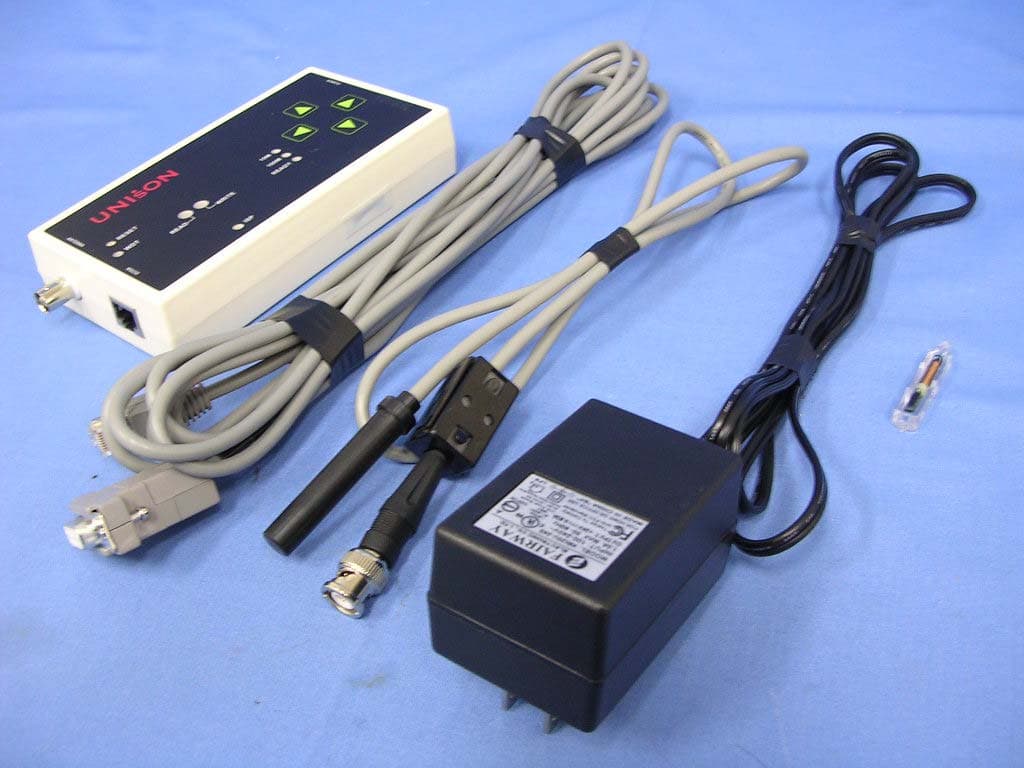
Click to zoom
Application Details
- Equipment Class
- DCD - Part 15 Low Power Transmitter Below 1705 kHz
- Date of Grant
- Apr 13, 2005
- Application Purpose
- Original Equipment
- Date of Application
- Apr 13, 2005
- Equipment Note
- Radio Frequency Identification (RFID)
- Frequency Range
- 0.13420000 - 0.13420000
- Country
- Taiwan
Documents & Files
Document Text
Text extracted from the exhibit documents filed with the FCC. Open a document above to read the original.
Users Manual
RFID Transponder Reader User Manual (Model: 88-157-101) FCC ID: S44RF88157101 DOCUMENT INFORMATION DOCUMENT ID: UT-RFID-LFRD157-MN01 VERSION NO: 1.9 ISSUED DATE: SEP , 1 , 2004 REVISIED DATE: APR , 14 , 2005 RFID Transponder Reader User Manual Version:1.9 This document is prepared by UNISON Technology Inc. All rights reserved. Page 2 of 31 IMPORTANT NOTES: This device complies with Part 15 of the FCC Rules. Operation is subject to the following two conditions: (1) this device may not cause harmful interference, and (2) this device must accept any interference received, including interference that may cause undesired operation. Any changes or modifications not expressly approved by the party responsible for compliance could void the authority to operate equipment. ! CAUTION: 01. Read and understand all safety and operating instructions before installing and operating the device. 02. This instruction is designed for specially trained personnel. This device is NOT intended for use by the “general population” in an uncontrolled environment. Installation, operation and error handling the device shall be carried out by specially trained personnel only. 03.The device cannot be sold retail ,to the general public or by mail order. It must be sold to dealers. 04. Install in accordance with the manufacturer's instructions only. 05.This product is designed to be mounted and operated in an industrial environment as a built-in-device only. It is not designed to be used as a stand-alone or a portable device or in a non-industrial environment, such as a household, vehicle or open-air environment. 06. This manual is designed for specially trained personnel only. This device must be installed and maintained by the manufacturer or its specially trained representatives. Intervention or error handling not expressively approved in this manual must be carried out by the manufacturer’s personnel only. If you are unsure about the qualifications that are actually required, contact the manufacturer. z Unqualified interventions may result in personal injury or damage to the device! 07. Do not connect the device to any kind of power supply such as a standard household power supply. The device should be connected to a power supply of the type described in these instructions only. 08. When you disconnect a cable, pull on its conductor and not on the cable itself. Keep the connector evenly aligned to avoid bending any connector pins. When you connect a cable, ensure that the connector pins are positioned correctly. RFID Transponder Reader User Manual Version:1.9 This document is prepared by UNISON Technology Inc. All rights reserved. Page 3 of 31 09. Never over bend the antenna cable or expose it to mechanical loads. 10. When replacement parts are required, use the replacement parts specified by the manufacturer only. Unauthorized substitutions may result in fire, electric shock, or other hazards. 11. This equipment generates , uses and can radiate radio frequency energy and, if not installed and used in accordance with the instructions, may cause harmful interference to radio communications. 12. Never locate the antenna so that it is very close to or touching parts of the body while transmitting. RFID Transponder Reader User Manual Version:1.9 This document is prepared by UNISON Technology Inc. All rights reserved. Page 4 of 31 TABLE OF CONTENT IMPORTANT NOTES AND CAUTION ................................................................ 2 1. INTRODUCTION ......................................................................................... 6 2. PRODUCT DESCRIPTION ............................................................................ 6 2.1. OVERVIEW .......................................................................................... 7 2.2. LAYOUT .............................................................................................. 8 2.3. FUNCTION ........................................................................................... 11 2.4. SPECIFICATION .................................................................................... 13 2.5. LOAD PORT INTEGRATION ..................................................................... 14 3. SECS OPERATION ...................................................................................... 15 3.1. INTRODUCTION .................................................................................... 15 3.2. SECS II MESSAGE .................................................................................. 15 3.2.1. Message Set .................................................................................... 15 3.2.2. Message Set Format .......................................................................... 16 3.3. INTRODUCTION TO SEMI E99 .................................................................. 20 3.3.1. State Model and Transition .................................................................. 21 3.3.2. Services ......................................................................................... 22 3.3.3. Service Operability ........................................................................... 23 4. ASCII OPERATION ..................................................................................... 23 4.1. HOST COMMAND FORMAT .....................................................................23 4.2. READER COMMAND FORMAT ................................................................. 24 5. SETUP ....................................................................................................... 25 5.1. INSTALLATION PROCEDURE .................................................................. 26 5.2. INITIAL TEST PROCEDURE ..................................................................... 26 6. TROUBLE SHOOTING ................................................................................. 27 6.1. ERROR INDICATOR ................................................................................ 27 6.1.1.…
Text truncated - open the document above for the full version.
Block Diagram
Radio Frequency Identification (RFID) Working Block Diagram EUT Model: 88-157-101 Radio Frequency Transponder Reader (134.2 kHz) Power Adapter 24V DC TAG Antenna Send Signal Feed Back HOST PC (WorkStation) Controller RS232 Passive TAG for Data Storage Customer Side
External Photos
Report No:053H045-F-R02-T Page: 26 of 34 Version:1.0 Attachement ¾ EUT Photograph (1) EUT Photo (2) EUT Photo
ID Label/Location Info
FCC ID.: S44RF88157101 13F-2, No. 289, Sec. 2, Kuang-Fu Rd., Hsin Chu., Taiwan, R.O.C. FCC ID and DoC Label The FCC ID and DoC Label will be placed on the equipment as shown in the photograph below. Radio Frequency IDentification (RFID) Model No.: 88-157-101 F F C C C C I I D D : : S S 4 4 4 4 R R F F 8 8 8 8 1 1 5 5 7 7 1 1 0 0 1 1 This device complies with Part 15 of the FCC Rules. Operation is subject to the following two conditions: (1) this device may not cause harmful interference and (2) this device must accept any interference received, including interference that may cause undesired operation. S/N: Made in Taiwan Trade name: UNISON Model number.: 88-157-101
ID Label/Location Info
FCC ID.: S44RF88157101 13F-2, No. 289, Sec. 2, Kuang-Fu Rd., Hsin Chu., Taiwan, R.O.C. FCC ID and DoC Label The FCC ID and DoC Label will be placed on the equipment as shown in the photograph below. Radio Frequency IDentification (RFID) Model No.: 88-157-101 F F C C C C I I D D : : S S 4 4 4 4 R R F F 8 8 8 8 1 1 5 5 7 7 1 1 0 0 1 1 This device complies with Part 15 of the FCC Rules. Operation is subject to the following two conditions: (1) this device may not cause harmful interference and (2) this device must accept any interference received, including interference that may cause undesired operation. S/N: Made in Taiwan Trade name: UNISON Model number.: 88-157-101
Internal Photos
Report No:053H045-F-R02-T Page: 27 of 34 Version:1.0 (3) EUT Photo (4) EUT Photo Report No:053H045-F-R02-T Page: 28 of 34 Version:1.0 (5) EUT Photo (6) EUT Photo Report No:053H045-F-R02-T Page: 29 of 34 Version:1.0 (7) EUT Photo Report No:053H045-F-R02-T Page: 30 of 34 Version:1.0 (8) EUT Photo Report No:053H045-F-R02-T Page: 31 of 34 Version:1.0 (9) EUT Photo (10) EUT Photo Report No:053H045-F-R02-T Page: 32 of 34 Version:1.0 (11) EUT Photo (12) EUT Photo Report No:053H045-F-R02-T Page: 33 of 34 Version:1.0 (13) EUT Photo (14) EUT Photo Report No:053H045-F-R02-T Page: 34 of 34 Version:1.0 (15) EUT Photo
Operational Description
Report No:053H045-F-R02-T Page: 5 of 26 Version:1.0 1.2. Operational Description The EUT is a Radio Frequency IDentification (RFID). The operation frequency 134.2 kHz. The characteristic of RFID depends on the operating frequency. Unison RFID Reader works In LF (Low Frequency) range of 134.2 kHz. It uses inductive coupling and FSK (Frequency shift Keying) technologies to transmit data between reader and tag. Non-contact communication reduces the abrasion of tag, and the read/write do not restrict within line of sight. In addition, the passive tag is energy by reader, no battery needed during operation, The cost of tag is reduced substantially.
Schematics
11 22 33 44 55 66 D D C C B B A A Ti tl e Nu mber Revi si on Size B Date: 2005/3/24 Sheet of Fil e: \\ MINDY\ \rf controller_4.Sch Drawn By: C1+ 1 V+ 2 C1- 3 C2+ 4 C2- 5 V- 6 T2 OUT 7 R2IN 8 R2OUT 9 T2 IN 10 T1 IN 11 R1OUT 12 R1IN 13 T1 OUT 14 GN D 15 VCC 16 MAX2 32U1 3 22 uF/ 25 VC2722 uF/ 25 VC28 22 uF/ 25 VC2622 uF/ 25 VC25 VCC RXD0TX D0 11 .0 5MHzU1 4 20 pC29 20 pC30 VCC 10 K R15 VCC VCC 12 POWERCON3 9 8 7 6 5 4 3 2 1 1KRP5 VCC TX CTSCIO TX CT 1 SCIO 2 GN D 3 GN D 4 VCC 5 AN T1 6 AN T2 7 RFM001U9 12 AN TCON4 1234 8765 DE VICE IDS3 VCC VCC 1KR18 TX + 1 TX - 2 RX+ 3 NC 4 NC 5 RX- 6 NC 7 NC 8 EA RT H 0 HO ST RJ3 RT TR 0. 1u F C24 RESETTX D0RXD0 P4.2 1 P1.0 2 P1.1 3 P1.2 4 P1.3 5 P1.4 6 P1. 5 7 P1. 6 8 P1. 7 9 RST 10 P3. 0 RXD 11 P4. 3 12 P3. 1 TXD 13 P3. 2 14 P3. 3 15 P3. 4 16 P3. 5 17 P3.6 18 P3.7 19 X2 20 X1 21 VSS 22 P4.0 23 P2.0 24 P2.1 25 P2.2 26 P2. 5 29 P2. 6 30 P2. 7 31 /PSE N 32 P2.3 27 P2.4 28 AL E 33 P4. 1 34 /E A 35 P0. 7 36 P0. 6 37 P0. 5 38 P0. 4 39 P0.3 40 P0.2 41 P0.1 42 P0.0 43 VDD 44 W7 8E 516 BPU1 2 RXD1TX D1 A0 1 A1 2 A2 3 VSS 4 SDA 5 SCL 6 WP 7 VCC 8 X2 4C02U1 0 SCLSDL VCC 10 KR410 KR8 VCC SCLSDL VCC TX CTSCIO ISP 12345 KE YPAD J3 0. 1u FC4 GR READ D7 GR WRIT E D8 1K R17 1K R19 1K R20 4. 7u HL5 10 0u F/1 6V C21 RFVCC RFVCC /PBRST 1 TD 2 TO L 3 GN D 4 RST 5 /RST 6 /ST ROBE 7 VCC 8 DS1232U1 1 WD T VCC 47 0R16 VCC WD T VCC DO GD2 33R26 33R27 0. 1u FC32 RST C 6 NO 5 NC 4 NC 1 NO 2 C 3 ISP SW1 ISP RST RESET 10 KR1 VCC -VG 2 -VG 3 NC 9 NC 11 5V OUT 14 GN D 16 24 VIN 22 24 VIN 23 24 V/ 5V MWU1 VCC C 6 NO 5 NC 4 NC 1 NO 2 C 3 RESETPB2 VCC 10 uFC1 ET X+ 1 ET X- 2 ERX+ 3 ERX- 4 LE D 1 0M 5 TX D 6 RXD 7 RTS 8 CTS 9 RESET 10 GN D 11 GN D 12 TX D1 13 PIO0 14 PIO1 15 PIO2 16 PIO3 17 LE D 1 00M 18 DCD0 19 DSR0 20 DT R0 21 GN D0 22 LE D REA DY 23 +5V 24 +5V 25 RXD1 26 NE 41 00 U1 5 TX + 1 TX - 2 RX+ 3 NC 4 NC 5 RX- 6 NC 7 NC 8 EA RT H 0 E.N ETRJ4 VCC RDY D9 1KR24 12 RSTJ4 10 0MD1 010 MD1 1 VCC 10 M 10 M HSMSTX DHSMSRXD 0. 1u FC33 C 6 NO 5 NC 4 NC 1 NO 2 C 3 LCD/ HSMSSW2 RXD1 TX D1 HSMSTXD HSMSRXD LCDRX D LCDT XD LCDT XD LCDRX D TL CD TL CD RLCD RLCD 33 0R6 33 0R5 24 V 24 V VCC VCC MOSRELA YU6 MOSRELA YU5 PC817U3 PC817U4 1KR3 1KR2 VCC VCC 4. 7KR9 4. 7KR7 3 4 74 HC04U2 B 1 2 74 HC04U2 A 24 V 24 V OU T1OU T2 OU T1OU T2 IN1IN2 IN1 IN2 24 V 24 V 7 6 5 4 3 2 1 4. 7KRP6 8 7 6 5 4 3 2 1 10 KRP4 123456 IO J1 22 0u F /1 6v C2 0. 1u FC3 0. 1u FC5 0. 1u FC6 VCC 0. 1u FC20
Test Report
Report No:053H045-F-R02-T Page: 1 of 34 Version:1.0 Test Report Product Name : Radio Frequency IDentification (RFID) Model No. : 88-157-101 FCC ID. : S44RF88157101 Applicant : ABON-TECH INTERNATIONAL CORP. Address : 13F-2, No. 289, Sec. 2, Kuang-Fu Rd., Hsin Chu., Taiwan, R.O.C. Date of Receipt:2005/03/10 Issued Date :2005/03/14 Report No. :053H045-F-R02-T The test results relate only to the samples tested. The test report shall not be reproduced except in full without the written approval of QuieTek Corporation. This report must not be used to claim product endorsement by NVLAP any agency of the U.S. Government Report No:053H045-F-R02-T Page: 2 of 34 Version:1.0 Test Report Certification Issued Date : 2005/03/14 Report No. : 053H045-F-R02-T Product Name : Radio Frequency IDentification (RFID) Applicant : ABON-TECH INTERNATIONAL CORP. Address : 13F-2, No. 289, Sec. 2, Kuang-Fu Rd., Hsin Chu., Taiwan, R.O.C. Manufacturer : ABON-TECH INTERNATIONAL CORP Model No. : 88-157-101 FCC ID. : S44RF88157101 Rated Voltage : AC 120V / 60Hz Trade Name : UNISON Applicable Standard : FCC CFR Title 47 Part 15 Subpart C 15.209: 2003 Test Result : Complied The test results relate only to the samples tested. The test report shall not be reproduced except in full without the written approval of QuieTek Corporation. Documented By : ( Sandy Chaung ) Tested By : ( Dampier Chang ) Approved By : ( James Chang ) Report No:053H045-F-R02-T Page: 3 of 34 Version:1.0 TABLE OF CONTENTS Description Page 1. GENERAL INFORMATION ............................................................................................ 4 1.1. EUT Description ............................................................................................................. 4 1.2. Operational Description.................................................................................................. 5 1.3. Test Mode....................................................................................................................... 6 1.4. Tested System Details .................................................................................................... 7 1.5. Configuration of tested System ...................................................................................... 7 1.6. EUT Exercise Software .................................................................................................. 8 1.7. Test Facility..................................................................................................................... 9 2. Conducted Emission.................................................................................................. 10 2.1. Test Equipment............................................................................................................. 10 2.2. Test Setup .................................................................................................................... 10 2.3. Limits ............................................................................................................................ 11 2.4. Test Procedure .............................................................................................................11 2.5. Test Specification.......................................................................................................... 11 2.6. Test Result.................................................................................................................... 12 2.7. Test Photo .................................................................................................................... 14 3. Radiated Emission ..................................................................................................... 15 3.1. Test Equipment............................................................................................................. 15 3.2. Test Setup .................................................................................................................... 15 3.3. Limits ............................................................................................................................ 16 3.4. Test Procedure ............................................................................................................. 16 3.5. Test Specification.......................................................................................................... 17 3.6. Test Result.................................................................................................................... 18 3.7. Test Photo .................................................................................................................... 22 Attachement......................................................................................................................................... 26 EUT Photograph........................................................................................................... 26 Report No:053H045-F-R02-T Page: 4 of 34 Version:1.0 1. GENERAL INFORMATION 1.1. EUT Description Product Name Radio Frequency IDentification (RFID) Trade Name UNISON Model No. 88-157-101 FCC ID S44RF88157101 EUT Voltage AC 120V / 60Hz Frequency Range 134.2 kHz Type of Modulation FSK Antenna Type Soldered on PCB Channel Number 1 Channel Control Non-Applied Component Passive tag 1 Set RS232 Cable Shielded, 5.0m Antenna Cable Shielded, 0.9m, one ferrite core bonded. Power Adapter FAIRWAY, WN20U-240 Cable Out: Non-Shielded, 1.8m Frequency of Each Channel: Channel Frequency Channel 1: 134.2 kHz Note: 1. This device is a 134.2 kHz device included a 134.2 kHz receiving function, and 134.2 kHz transmitting function. 2. These tests were conducted on a sample of the equipment for the purpose of demonstrating compliance with Part 15 Subpart C Paragraph 15.209. 3. This device is a composite device in accordance with Part 15 regulations. The function receiving was measured and made a test report that the report number is 053H045-F-R01-R under Decla…
Text truncated - open the document above for the full version.
Test Setup Photos
Report No:053H045-F-R02-T Page: 14 of 34 Version:1.0 2.7. Test Photo Test Mode : Mode 1: Transmit Description: Front View of Conducted Emission Test Setup Test Mode : Mode 1: Transmit Description: Back View of Conducted Emission Test Setup Report No:053H045-F-R02-T Page: 22 of 34 Version:1.0 3.7. Test Photo Test Mode : Mode1: Transmit Description: Front View of Radiated Emission (X-axis) (Loop) Test Mode : Mode1: Transmit Description: Back View of Radiated Emission (X-axis) (Loop) Report No:053H045-F-R02-T Page: 23 of 34 Version:1.0 Test Mode : Mode1: Transmit Description: Front View of Radiated Emission (Y-axis) (Loop) Test Mode : Mode1: Transmit Description: Back View of Radiated Emission (Y-axis) (Loop) Report No:053H045-F-R02-T Page: 24 of 34 Version:1.0 Test Mode : Mode1: Transmit Description: Front View of Radiated Emission (Z-axis) (Loop) Test Mode : Mode1: Transmit Description: Back View of Radiated Emission (Z-axis) (Loop) Report No:053H045-F-R02-T Page: 25 of 34 Version:1.0 Test Mode : Mode1: Transmit Description: Front View of View of Radiated Emission (Y-axis) Test Mode : Mode1: Transmit Description: Back of View of Radiated Emission (Y-axis)
Contact Information
Applicant
Jason Lo(Supervisor)
Test Firm
DEKRA Testing and Certification Co., Ltd.Sky Hsu
Technical Specifications
| # | Rule Parts | Frequency Range | Power Output |
|---|---|---|---|
| 1 | 15C | 0.1342 MHz - 0.1342 MHz | - |