S4BLD22PIC785S450Tire Pressure Monitoring System
FuZhou Tinyo Technology Co., Ltd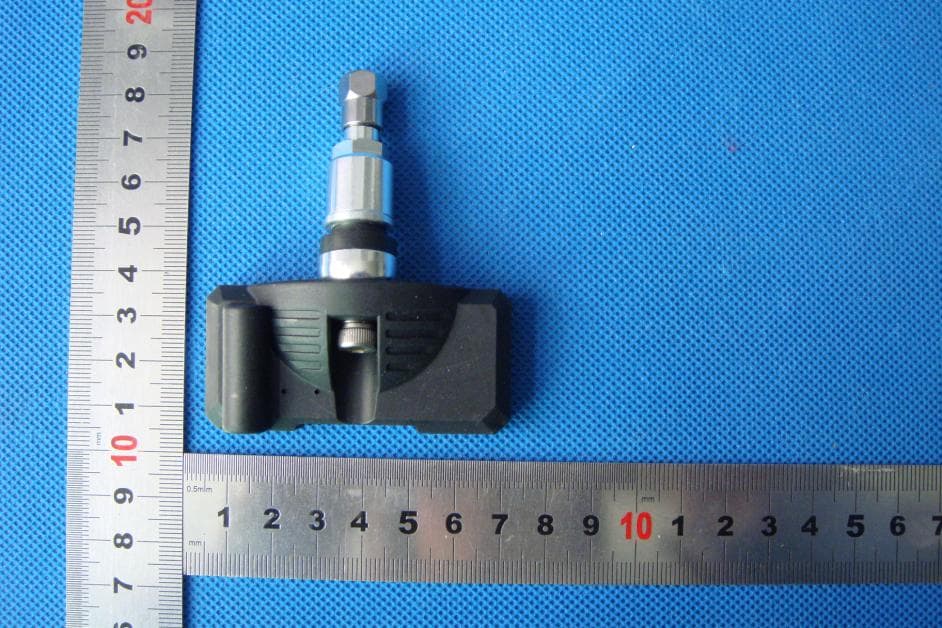
Click to zoom
Application Details
- Equipment Class
- DSC - Part 15 Security/Remote Control Transmitter
- Date of Grant
- Mar 17, 2013
- Application Purpose
- Original Equipment
- Date of Application
- Feb 14, 2013
- Equipment Note
- Tire Pressure Monitoring System
- Frequency Range
- 433.92000000 - 433.92000000
- Country
- China
Documents & Files
Document Text
Text extracted from the exhibit documents filed with the FCC. Open a document above to read the original.
Users Manual
TYPEKIT-100 Tire Pressure Monitor System (TPMS) FuZhou Tinyo Technology Co., Ltd USER MANUAL 1 / 13 FCC STATEMENT 1. This device complies with Part 15 of the FCC Rules. Operation is subject to the following two conditions: (1) This device may not cause harmful interference. (2) This device must accept any interference received, including interference that may cause undesired operation. 2. Changes or modifications not expressly approved by the party responsible for compliance could void the user's authority to operate the equipment. USER MANUAL 2 / 13 WARNING 1. This product has been already set up parameters, please turn the sensor follow by the coding instructions, install on the corresponding tire position of " left front, left, right, right after ". Tire balance after sensor installed, main power switch, system start self-test after about 10 seconds, then can be normal work, without parameter setting, adjustment again. 2. When the system displays a "di di di" buzzer or failure icon flashes continuously, please as soon as possible speed down to safety or go to tire repair, check the tire pressure condition, in order to ensure your safety. 3. This system can monitor effectively on the tire pressure and temperature, but could not prevent the occurrence of unexpected incidents. By using this system users should ensure that the car in the normal tire pressure and temperature conditions of running, and avoid the use of bad quality or badly worn tyre. 4. The system has the function of automatic monitoring, Real-time monitoring for gas leakage, low pressure, high pressure, high temperature and malfunction of sensor, automatic sound & light alarm, the driver not need frequent pushing the button to view in order to avoid distract attention during the driving. 5. In order to avoid injury system equipments, please do not attempt to remove any of the outer casing of components. USER MANUAL 3 / 13 CATALOGUE FCC STATEMENT ........................................................................................................................ 1 WARNING .................................................................................................................................. 2 CATALOGUE ............................................................................................................................... 3 CHAPTER 1 FUNCTION INTRODUCE ............................................................................... 4 CHAPTER 2 DISPLAY KEY-PRESS FUNCTION DIRCTION ................................................... 4 CHAPTER 3 SCREEN DISPLAY PAGE .................................................................................... 4 CHAPTER 4 PRINCIPLES .................................................................................................. 5 CHAPTER 5 SETTING DIRCTION ...................................................................................... 6 PARAMENTERS (PRESSURE, TEMPERATURE ALARM THRESHOLD VALUE SETTING) . 6 1. PRESSURE CAP SETTING ................................................................................ 6 2. PRESSURE CAP SETTING ................................................................................ 7 3.TEMPERATURE UPPER LIMIT SETTING (SIMILAR TO THE UPPER PERSSURE LIMIT SETTING) .................................................................................................. 7 4.TIRE CODE SETTING ........................................................................................ 7 5.TEMPERATURE DISPLAY UNIT ......................................................................... 8 6. PRESSURE DISPLAY UNIT ............................................................................... 8 7.RESTORE FACTORY SETTING ........................................................................... 9 CHAPTER 6 ALARM FUNCTION ....................................................................................... 9 CHAPTER 7 INSTALLATION DIRECTION ........................................................................... 9 1.DISPLAY INSTALLATION ................................................................................ 9 2.POWER INSTALLATION................................................................................. 9 3.SENSOR INSTALLATION .............................................................................. 10 CHAPTER 8 TECHNICAL PARAMETER ............................................................................... 11 CHAPTER 9 TERMS OF SERVICE .................................................................................... 11 COMMON PROBLEM ....................................................................................................... 12 USER MANUAL 4 / 13 CHAPTER 1 FUNCTION INTRODUCE TYPEKIT-100 tire pressure monitor system can real-time monitoring of tire pressure, and alarm for the high or low pressure, air leakage, inner tire temperature and sensor failure, reduce traffic accident probability. System factory default when the air pressure is lower than 1.9Kg/cm 2 or higher than 3.OKg/cm 2 , leakage, internal temperature higher than 70°C, time is not received sensor signal will automatically alarm ( not recommended to modify the above alarm threshold ). Overpressure alarm: alarm when excessive tire pressure Undervoltage warning: alarm when low tire pressure Temperature alarm: alarm when high tire temperature Leakage alarm: alarm when tire fast leakage Failure alarm: alarm when sometime is not received sensor signal Setting function: setting pressure & temperature alarm threshold value code Learning function: replacement for sensor Tire rotation function: mutual exchange for tire CHAPTER 2 DISPLAY KEY-PRESS FUNCTION DIRCTION 【OK】 OK 【C】 CLOSE DELETE CANCEL BACK 【<】 MOVE ADJUST 【>】 MOVE ADJUST 【】 ON/OFF CHAPTER 3 SCREEN DISPLAY PAGE Starting up into a main page: USER MANUAL 5 / 13 If a tire temperature or pressure anomaly, backlight will automatically light up, screen corresponding to the position in red font, while …
Text truncated - open the document above for the full version.
External Photos
FuZhou Tinyo Technology Co., Ltd Model: TYREKIT-100 APPENDIX B - EUT PHOTOGRAPHS EUT - Rear View 1 EUT - Rear View 2 FuZhou Tinyo Technology Co., Ltd Model: TYREKIT-100 EUT - Rear View 3 EUT - Rear View 4 FuZhou Tinyo Technology Co., Ltd Model: TYREKIT-100 EUT - Rear View 5 EUT - Rear View 6
ID Label/Location Info
FuZhou Tinyo Technology Co., Ltd Model: TYREKIT-100 Proposed Label Location on EUT FCC ID Label Location
ID Label/Location Info
FuZhou Tinyo Technology Co., Ltd Model: TYREKIT-100 APPENDIX A - PRODUCT LABELING Proposed FCC ID Label Format FCC ID: S4BLD22PIC785S450
Internal Photos
FuZhou Tinyo Technology Co., Ltd Model: TYREKIT-100 APPENDIX C - EUT INTERNAL PHOTOGRAPHS EUT – Inside View EUT – PCB View 1 FuZhou Tinyo Technology Co., Ltd Model: TYREKIT-100 EUT – PCB View 2 EUT – PCB View 3 FuZhou Tinyo Technology Co., Ltd Model: TYREKIT-100 EUT – Battery View 1 EUT – Battery View 2
Test Report
. FCC Part 15C Measurement And Test Report For FuZhou Tinyo Technology Co., Ltd Rm.819,No.A2 Office Building, Wanda Plaza, No.8 Aojiang Road, Taijiang District,Fuzhou,Fujian,China. FCC ID: S4BLD22PIC785S450 December 27, 2012 This Report Concerns: Original Report Equipment Type: The Tire Pressure Monitor System Report Number: MTI121218003RF Test Engineer: Bill Chen Reviewed By: Jason Zheng Approved & Authorized By: Hebe Lee Test Date: December 18-27,2012 Prepared By: Shenzhen Microtest Technology Co.,Ltd 6F, Zhongbao Building, Gushu, Bao’an District, S henzhen, P.R.China Tel: +86-755-8885 0135 Fax: +86-755-8885 0136 Note: This test report is limited to the above client company and the product model only. It may not be duplicated without prior written consent of MTI Technology Laboratory Ltd. Report No.:MTI121218003RF Page 2 of 29 TABLE OF CONTENTS 1. GENERAL INFORMATION....................................................................................................................3 1.1 PRODUCT DESCRIPTION FOR EQUIPMENT UNDER TEST (EUT)....................................................................................3 1.2 RELATED SUBMITTAL(S) / GRANT (S).......................................................................................................................3 1.3 TEST METHODOLOGY...........................................................................................................................................3 1.4 TEST FACILITY.....................................................................................................................................................4 2. SYSTEM TEST CONFIGURATION........................................................................................................5 2.1 EUT DESCRIPTION..............................................................................................................................................5 2.21 EUT CONFIGURATION........................................................................................................................................5 2.3 EUT EXERCISE...................................................................................................................................................5 2.4 GENERAL TEST PROCEDURES................................................................................................................................5 2.4 LIST OF MEASURING EQUIPMENTS USED.................................................................................................................6 3. SUMMARY OF TEST RESULTS............................................................................................................7 3.1 MODES OF OPERATION:.........................................................................................................................................7 3.2 TIMING DIAGRAMS OF DIFFERENT TRANSMISSION MODES:...........................................................................................7 4. ANTENNA REQUIREMENT...................................................................................................................9 4.1 STANDARD APPLICABLE........................................................................................................................................9 4.2 ANTENNA CONNECTED CONSTRUCTION...................................................................................................................9 5. CONDUCTED DISTURBANCES..........................................................................................................10 5.1. MEASUREMENT UNCERTAINTY............................................................................................................................10 5.2. LIMIT OF CONDUCTED DISTURBANCES (CLASS B)...................................................................................................10 5.3. EUT SETUP.....................................................................................................................................................10 5.4. INSTRUMENT SETUP..........................................................................................................................................10 5.5. TEST PROCEDURE............................................................................................................................................11 5.6. SUMMARY OF TEST RESULTS..............................................................................................................................11 5.7. TEST RESULT...................................................................................................................................................11 6. §15.205, §15.209, §15.231- RADIATED EMISSION.............................................................................12 6.1 DUTY CYCLE.....................................................................................................................................................12 6.2 STANDARD APPLICABLE......................................................................................................................................17 6.3 EUT SETUP......................................................................................................................................................18 6.4 TEST EQUIPMENT LIST AND DETAILS.....................................................................................................................18 6.5 TEST PROCEDURE.............................................................................................................................................18 6.6 CORRECTED AMPLITUDE & MARGIN CALCULATION..................................................................................................19 6.7 TEST RESULT....................................................................................................................................................19 7 OCCUPIED BANDWIDTH.................................…
Text truncated - open the document above for the full version.
Test Setup Photos
FuZhou Tinyo Technology Co., Ltd Model: TYREKIT-100 APPENDIX D - TEST SETUP PHOTOGRAPHS Radiation Emission Test Setup (30MHz to 1GHz) Radiation Emission Test Setup (Above 1GHz)
Contact Information
Applicant
Fan zhang(Manager)
Test Firm
Shenzhen NTEK Testing Technology Co., Ltd.Jason Chen
Technical Specifications
| # | Rule Parts | Frequency Range | Power Output |
|---|---|---|---|
| 1 | 15.231(e) | 433.92 MHz - 433.92 MHz | - |