S4FLIDEUR4100Mini Reader Transponder System, LID EUR 4100
Gustav Wilms Spezialpaletten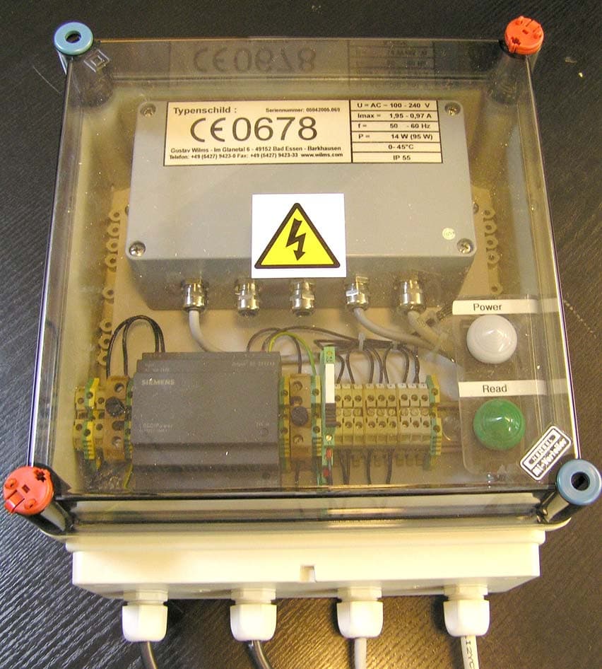
Click to zoom
Application Details
- Equipment Class
- DCD - Part 15 Low Power Transmitter Below 1705 kHz
- Date of Grant
- Oct 19, 2005
- Application Purpose
- Original Equipment
- Date of Application
- Oct 19, 2005
- Equipment Note
- Mini Reader Transponder System, LID EUR 4100
- Frequency Range
- 0.12500000 - 0.12500000
- Company
- Gustav Wilms Spezialpaletten
- Country
- Germany
Documents & Files
Document Text
Text extracted from the exhibit documents filed with the FCC. Open a document above to read the original.
Users Manual
Annex No.4b Users Manual LID EUR 4100 Mini Reader the trovan ® Identification System EUR 4100 Mini Reader Firma Gustav Wilms Tel.: +49-(0)5427-9423-0 Im Glanetal 6 Fax.: +49-(0)5427-9423-33 D 49152 Bad Essen eMail: [email protected] http://www.wilms.com GERMANY EUR 4100 Version Wilms Firmware 2.03 Technical changes without notice Page 1 of 26 Installation Manual for the EUR 4100 Mini Reader Version Wilms 2.03 Copying this document and giving it to others as well as the use or communication of the contents thereof, are forbidden without express authority. Offenders are liable to the payment of damages. All rights are reserved in the event of the grant of a patent or the legal protection of a registered design October 2005 the trovan ® Identification System EUR 4100 Mini Reader Firma Gustav Wilms Tel.: +49-(0)5427-9423-0 Im Glanetal 6 Fax.: +49-(0)5427-9423-33 D 49152 Bad Essen eMail: [email protected] http://www.wilms.com GERMANY EUR 4100 Version Wilms Firmware 2.03 Page 2 of 26 Technical changes without notice Table of Contents Page 1. Safety and Application Instructions............................................................................... 3 1.1 General.................................................................................................................... 3 1.2 Transport, Storage and Installation.......................................................................... 4 1.3 Electrical Radiation.................................................................................................. 4 1.4 Approval certificate.................................................................................................. 5 2. Introduction..................................................................................................................... 6 3. Technical Data................................................................................................................ 6 3.1 Mechanical Characteristics of the Reader................................................................ 6 3.2 Mechanical Characteristics of the Antenna.............................................................. 7 3.3 Block Diagram......................................................................................................... 8 3.4 Electric Characteristics Reader................................................................................ 9 3.5 Electric Characteristics Printed circuit board EUR-4100.......................................... 9 3.6 Electric Characteristics Antenna driver EUR-3110................................................... 9 3.7 The EUR-4100 Printed circuit board........................................................................ 10 3.8 Connection Characteristics of the Digital Inputs....................................................... 11 3.9 Connection Characteristics of the Relay Outputs..................................................... 11 3.10 Pin Configuration of the RS 232 Interface................................................................ 11 3.11 Pin Configuration of the Terminal Blocks (for antenna, power lines, etc.)................ 11 3.12 Antenna cable......................................................................................................... 11 3.13 DIP-Switche............................................................................................................ 12 3.14 Lights...................................................................................................................... 12 4. Firmware 2.03 Version Wilms....................................................................................... 13 4.1 Security of the Data Transfer....................................................................... 14 4.2 Command Set of the Data Transfer............................................................... 14 5. Putting into Operation.................................................................................................... 15 6. Trouble Shooting............................................................................................................ 15 7. Antennas........................................................................................................................ 16 8. Special Models RS 422 Interface.................................................................................. 16 9. Protocol Format............................................................................................................. 17 10. Command Set................................................................................................................ 18 11. Setup Menu.................................................................................................................... 22 12. Error Codes................................................................................................................... 24 13. Hyper Terminal Example................................................................................................ 25 the trovan ® Identification System EUR 4100 Mini Reader Firma Gustav Wilms Tel.: +49-(0)5427-9423-0 Im Glanetal 6 Fax.: +49-(0)5427-9423-33 D 49152 Bad Essen eMail: [email protected] http://www.wilms.com GERMANY EUR 4100 Version Wilms Firmware 2.03 Technical changes without notice Page 3 of 26 1. Safety and Application Instructions The directions in this chapter must be absolutely observed for following reasons: - Safety for people and maschines - Function and susceptibility to faults - Technical inspectorate acceptance and certification - Guarantee and warranties This instruction manual must be made available to any user. Before working with this unit the user must be familiarized with it. This is especially true for the attention, safety and warning guides. The meaning of the pictograms used in this manual are: Danger Attention Attention Information Electric radio observe at Help Shock Radiation all costs Tip 1.1 General Danger to Life Transponder …
Text truncated - open the document above for the full version.
Block Diagram
Annex No.6 Page 1 of 1 Block Diagram : LID EUR 4100 Mini Reader Transponder System Oscillator frequencies generated or used in the device: : 7.3728 MHz, 125 KHz IC Motorola MC68HC11F1CFN4 * 1 * 1 Q1: 7.3728 MHz
Cover Letter(s)
m. dudde hochfrequenz-technik Rottland 5a, D-51429 Bergisch-Gladbach DIN EN ISO/IEC 17025 zertifiziert Akkreditiertes Testhaus - Reg.-Nr.: TTI-P-G128/96 Tel. : +49 22 07 - 96 89 - 0 Fax : +49 22 07 - 96 89 - 20 email: [email protected] www.dudde.com Federal Communications Commission 7435 Oakland Mills Road Columbia, MD 21046 Gentlemen: This letter is to comply with Section 0.457(d)(2)(i) pertaining to confidential material. Gustav Wilms Spezialpaletten, Im Glanetal 6, D-49152 Bad Essen-Barkhausen / Germany would like the following documents regarding this submission for FCC ID: S4FLIDEUR4100 to be kept confidential. Mini Reader Transponder System, LID EUR 4100 1. Page 2 to 14 Annex no. 7 document “Schematics” The above material contains trade secret or technical data, which would customarily be guarded from competitors. We do not want these documents to be accessible to the general public. Sincerely, m. dudde hochfrequenz-technik Ralf Trepper
External Photos
Annex No.1 Page 1 of 2 External Photographs of the Equipment Under Test EXTERNAL FRONT VIEW PHOTO (LID EUR 4100 Reader) Annex No.1 Page 2 of 2 (LID EUR 4100 Loop antenna)
ID Label/Location Info
Annex No.4 Page 1 of 2 FCC ID LABEL SAMPLE SKETCH OF FCC ID LABLE LOCATION FCC ID: S4FLIDEUR4100 IC: 5764A-LIDEUR4100 Annex No.4 Page 2 of 2 FCC ID: S4FLIDEUR4100 IC: 5764A-LIDEUR4100
Internal Photos
Annex No.2 Page 1 of 2 Internal Photographs of the Equipment Under Test INTERNAL UPPER SIDE PHOTO (LID EUR 4100 Reader) Annex No.2 Page 2 of 2 INTERNAL UPPER SIDE PHOTO (LID EUR 4100 Loop antenna)
Operational Description
371.128.500.FB Edition: OE Page: 1 1. Processor and RS232: 2. Power supply and display elements: Office:Management:Amends for:Date: ID-M AEG ID The reset circuit of IC 10 resets the micro controller, after switching on the power supply. IC1 is driven with an external program storage of IC2. IC5 places the processor signals E and R/WB into the signals/OB and / WE around. If / OE=0, this recieves through the / CSROM of the selected storage program, program data from the processor over PF0.. PF7 and PB0.. PB7 of the chosen address. By means of JP1 and JP2, two different terminal assignments of IC2 can be chosen, 27C256 (EPROM) and 62256, static RAM. JP1 and JP2 are by default in the position 12 (EPROM) and after mounting, IC2 can no longer be altered. By means of JP3, the boat mode is fixed. JP3 is open per default. This setting should not be altered. With SW1 and RN2, the logic levels of all eight PE - Port pins of IC1 can be put on any values. AEG Identificationssysteme GmbH Function description for reading appliances LID EUR 4100 By means of RN1, the level at the processor management PA1, RX, becomes TX. PA3PA0 and MODA weak potential, are put on High-Potential. ICI is a micro controller clocked with 7,3728 MHz, whose internal quarz osillater are driven in parallel resonance with Q1, C1 and C2, as well as R1 and R50. Over X4, the Optic coupler O1 can be switched on by supplying a +24V DC current. By means of the parts D15, R14, R3 and C5 the level is changed via the X4 signal, to a Low pass filtered DC current, that is memorized in the Optic coupler entrance. The Open Collector Schmitt-Trigger exit of the Optic coupler O1 is in the resistance network RN3 terminated, with a pull up resistance and controls the micro controller entrance PA1, as well as the light diode driven by means of IC3A D1. IC11 serves the level change for the RS232-Interface. IC11 has integrated feed charges, with which standard levels are generated, at their disposal. The processor signals TX, RX, PA3 and PA0 are driven through IC11 or are received. PA0 receives the CTS signal PA3 sends the RTS while TX and RX guarantee the bidirectional communication. The condensers C29.. C33, as well as C44, C58, C61 and C62 smooth the electricity on the Vcc- Pins through the integrated hookup situated on the circuit board. Quality control: The ARE 002 is provided through X5 with 24V DC. S11, together with D9, D11 L7 and F11 serves for the safeguarding of the supply entrance against surge over voltage, pole change, interferance voltage and sturgeon tension. Particularly C48, C60, L7 and F11 suppress sturgeon frequencies, that penetrate into the ARE 002 or that try to get out. The constant voltage regulators IC 9 and IC6, together with the supression elements C41, C59, C39 C42 R2, C37 and C40, regulate and provide the +12 V and +5 V for the reading appliance circuit. 371.128.500.FB Edition: OE Page: 2 The individual indications of the LEDs: LED1:Antenna on = reading process active, (solid-wired with ANT-PWR) LED2:last reading process NoRead, (solid-wired - functionality like QN1) LED3:last reading process successfull, (solid-wired - functionality like QR1) LED4:Status dig. Entrance (solid-wired) LED5:Error - at the moment only antenna mistakes (program-controlled) LED6:Opperating system and Life indication, blinks, (program-controlled) LED7:RxD (solid-wired) LED8:TxD (solid-wired) LED9:Interference levels (solid-wired) 3. Filter und Synchronisation: Two seperate galvanic consumers can be connected at X2 to the ARE 002 hardware. The relais K1 and K2 act as turnkeys for closed and and open contacts ready. The switch condition of the two relais is steered by the processor signal PG0 and PG1 over IC3F and IC3E. Over D3 and D8, voltage peaks are destroyed, that are generated in the switch off moment of K1 and K2. AEG Identificationssysteme GmbH X1 is the Antenna port. The antenna is fed over the pins 2 and 4 with earth, and over pin 5 with switched 12 V DC. T3 is used for turning the antenna on and off. T3 is controlled over IC3D of the processor circuits of PG2. The antenna delivers the data signal, in which a higher carrier signal exists, and the Sync-Signal, that has the same phase as that of the carrier, are sent back to the ARE 002. Both signals are evaluated in the filter and synchronization step. Additionally C12, L2 and C13 form a deep pass. The filtered signal at the beginning is coupled into U1 into the operation intensifier switched as Impedence converter over C14. R13, R20 and C21 generate a high frequency-free advance signal, that defiy through R22 the work point of U1. C15, together with R24 and R25, form a RC-Heigh pass filter with an Corner frequence of approximately 6.5kHz. The amplification of U1 becomes exclusive through the relationship. The light diodes D1, D2, D4, D5, D6, D12, D22, D23 and D24 serve the visual supervision of the processor signals of PG0.. PG2, PA1, PA3, PA6, RX, TX and the interference level detector around the comparator U6A. Over C6 the antenna signal with stronger carrier component in the 64kHz-Bandpass with C7 and L1, and the 64kHz-Serial switching of C12, C13, and L2 are coupled with signal heightening. The filter circuit of the ARE 002 consists of the 128 kHz-carrier frequence with the following steps with passive amplification and two identical consequence steps, that amplify every spectral component in the 64kHz-Frequency range for itself, but suppresses the 128kHz carrier signal. Function description for reading appliances LID EUR 4100 AEG ID The signals of the serial interface are available at X3. All four data points RTS, TXD, CT and RXD are by means of the spools L8, L9, L10 and L12 protected against radiated interference from outside. If JP4 is closed, the RS232 hand shake hardware-wise is no longer carried out. In this case the ARE 002 can only execute communication with the Host over three wires.
Test Report
Test Report : 05002625 Page 1 of 22 EUT : LID EUR 4100 Mini Reader Transponder System FCC ID: S4FLIDEUR4100 Issue date: 2005-09-15 TTI-P-G-128/96 Test Report acc. to the relevant standard: 47 CFR Part 15 C –Intentional Radiators Measurement Procedure: ANSI C63.4 - 1992 relating to Gustav Wilms Spezialpaletten LID EUR 4100 Mini Reader Transponder System Measurement of Radio- Noise Emissions from Low Voltage Electrical and Electronic Equipment Technical characteristics and test methods for radio equipment in the frequency range 9 kHz to 40 GHz Test Report : 05002625 Page 2 of 22 EUT : LID EUR 4100 Mini Reader Transponder System FCC ID: S4FLIDEUR4100 Issue date: 2005-09-15 Manufacturer’s details Manufacturer Gustav Wilms Spezialpaletten Manufacturer’s grantee code Im Glanetal 6 D-49152 Bad Essen-Barkhausen Germany Tel.: +49 5427 9423-0 Fax : +49 5427 9423-33 Manufacturer’s address E-mail: [email protected] 47 CFR Part 15C - Intentional Radiators Relevant standard used ANSI C63.4-1992 Test report prepared by Ralf Trepper m.dudde hochfrequenz-technik (laboratory) Rottland 5a D-51429 Bergisch Gladbach Germany Phone: +49 2207 96890 Fax : +49 2207 968920 Technical engineer E-mail: [email protected] Equipment Under Test (EUT) Equipment category Inductive system Trade name wilms Type designation LID EUR 4100 Mini Reader Transponder System Serial no. 05042005.069 --- Variants Test Report : 05002625 Page 3 of 22 EUT : LID EUR 4100 Mini Reader Transponder System FCC ID: S4FLIDEUR4100 Issue date: 2005-09-15 0 Test result CFR Section Report Chapter Requirements Headline Test result OK 15.203 10.1 Antenna Requirement pass fail n.a. 15.109(a) 15.209 10.2 Radiated spurious emissions pass fail n.a. 15.107(a) 10.3 Conducted emissions pass fail n.a. Test requirements kept yes no . Signature test personnel ........................................ Ralf Trepper . Signature of the company official ......................................... Manfried Dudde Test Report : 05002625 Page 4 of 22 EUT : LID EUR 4100 Mini Reader Transponder System FCC ID: S4FLIDEUR4100 Issue date: 2005-09-15 List of contents Page 0 Test result............................................................................................................................................. 3 1 Testing laboratory................................................................................................................................5 2 Introduction......................................................................................................................................... 5 3 Product................................................................................................................................................. 6 4 Test schedule........................................................................................................................................ 6 5 Product and measurement documentation......................................................................................... 7 6 Observations and comments................................................................................................................ 7 7 Summary.............................................................................................................................................. 7 8 Conclusions......................................................................................................................................... 8 9 Operation description.......................................................................................................................... 9 10.1 Antenna Requirement..................................................................................................................... 10 10.1.1 Regulation ...................................................................................................................................... 10 10.1.2 Result ............................................................................................................................................. 10 10.2 Radiated emission........................................................................................................................... 11 10.2.1 Regulation ...................................................................................................................................... 11 10.2.2 Test equipment ............................................................................................................................... 12 10.2.3 Test procedures............................................................................................................................... 13 10.2.4 Calculation of field strength Section 15.209 below 30 MHz ........................................................... 14 10.2.5 Calculation of field strength Section 15.209 above 30 MHz ........................................................... 14 10.2.6 Calculation of the field strength ...................................................................................................... 15 10.2.7 Calculation of Average Correction Factor....................................................................................... 15 10.3 Conducted emissions...................................................................................................................... 19 10.3.1 Regulation ...................................................................................................................................... 19 10.3.2 Test equipment ............................................................................................................................... 19 10.3.3 Test procedures............................................................................................................................... 19 10.3.4 Test results...................................................................................................................................... 20 11…
Text truncated - open the document above for the full version.
Test Setup Photos
Annex No.6 Page 1 of 3 Test Setup Photos : Radiated emissions Annex No.6 Page 2 of 3 Annex No.6 Page 3 of 3 Test Setup Photos : AC Power line conducted emissions
Contact Information
Applicant
Rolf Hoppe(Material economist)
Technical Contact
m.dudde high frequency technologyMr. Ralf Trepper
[email protected]+49 2207 9689 - 0
Rottland 5A · Bergisch Gladbach · Germany
Test Firm
m. dudde hochfrequenz-technikManfred Dudde
Technical Specifications
| # | Rule Parts | Frequency Range | Power Output | Tolerance |
|---|---|---|---|---|
| 1 | 15C | 0.125 MHz - 0.125 MHz | - | Hz |