S4TIRS04183Soil Tension Measurement Sensor
Hortau, Inc.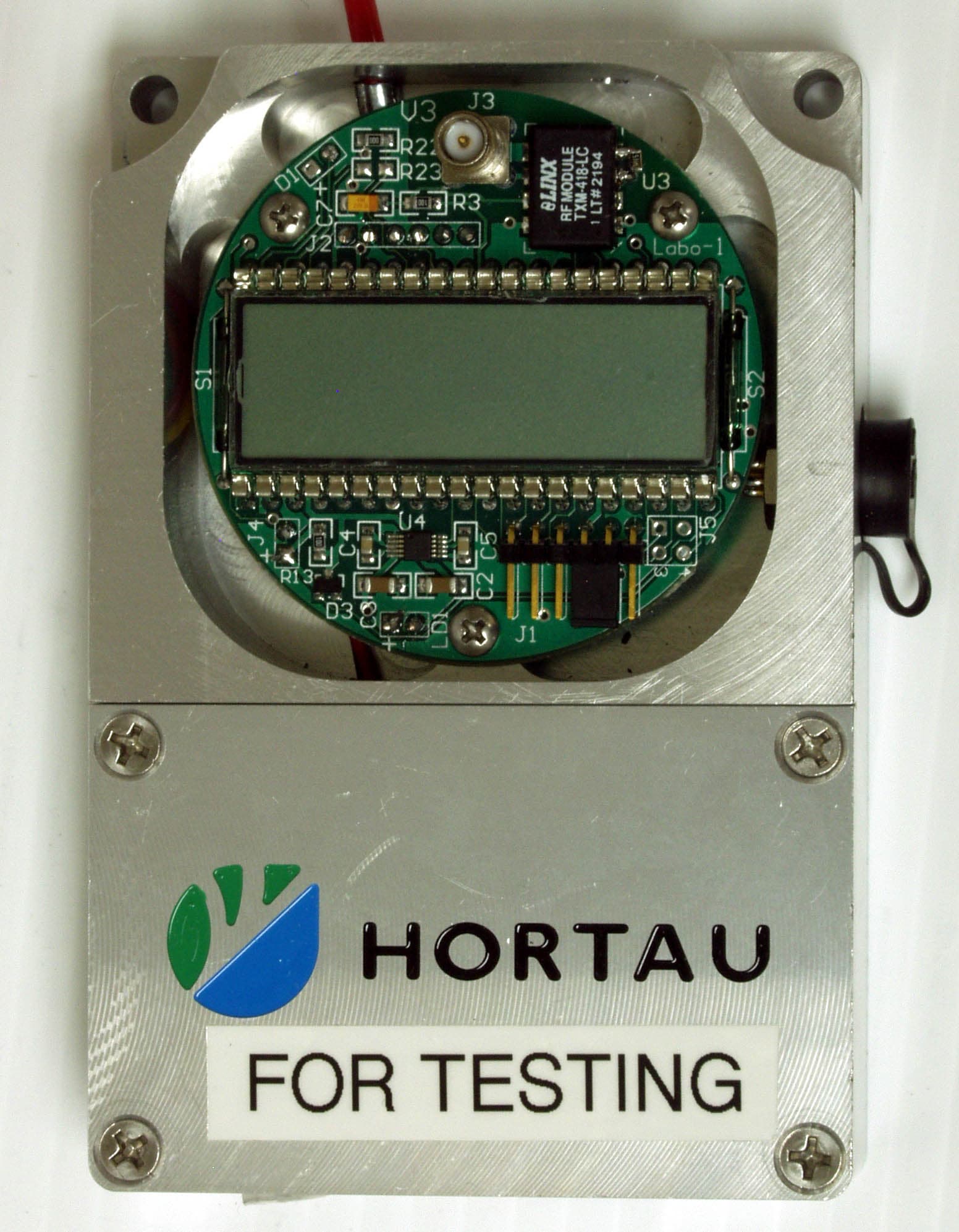
Click to zoom
Application Details
- Equipment Class
- DXX - Part 15 Low Power Communication Device Transmitter
- Date of Grant
- Jan 28, 2008
- Application Purpose
- Original Equipment
- Date of Application
- Jan 27, 2008
- Equipment Note
- Soil Tension Measurement Sensor
- Frequency Range
- 418.00000000 - 418.00000000
- Company
- Hortau, Inc.
- Country
- Canada
Documents & Files
Document Text
Text extracted from the exhibit documents filed with the FCC. Open a document above to read the original.
Users Manual
IRROLIS SENSE Tx SOIL AND SUBSTRATE TENSION MEASUREMENT IMPORTANT Before using or preparing your IRROLIS SENSE Tx, check that you have all parts at hand and in good working order. Handle the IRROLIS SENSE Tx with care at all times. The Ceramic Tip MUST be in contact with soil or substrate in order to generate an accurate reading. Do NOT put the Ceramic Tip in contact with oil, fats or any contaminant that could affect its wetability. Never totally immerse the IRROLIS SENSE Tx. The IRROLIS SENSE Tx is sealed and cannot be opened except for the Water Inlet and the Ceramic Tip which can be replaced if broken. Protect the Ceramic Tip at all times against shocks. The IRROLIS SENSE Tx should be protected at all times against frost. Under no circumstances should the storage temperature be bellow 5 ºC (40 Fahrenheit). Avoid exposure to magnetic fields. Do not expose to extreme temperatures. The user manual or instruction manual for an intentional or unintentional radiator shall caution the user that changes or modifications not expressly approved by the party responsible for compliance could void the user’s authority to operate the equipment. Operation is subject to the following two conditions: (1) This device may not cause interference, and (2) this device must accept any interference, including interference that may cause undesired operation of the device. To reduce potential radio interference to other users, the antenna type and its gain should be so chosen that the equivalent isotropically radiated power (EIRP) is not more than that required for successful communication. This equipment has been tested and found to comply with the limits for Class A digital device, pursuant to Part 15 of FCC Rules. These limits are designed to provide reasonable protection against harmful interference when the equipment is operated in a commercial environment. This equipment generates, uses, and can radiate radio frequency and, if not installed and used in accordance with the instruction manual, may cause harmful interference to radio communications. Operation of this equipment in a residential area is likely to cause harmful interference in which case the user will be required to correct the interference at its own expense. This device has been designed to operate with an antenna having a maximum gain of 2.2 dB. Antenna having a higher gain is strictly prohibited per regulations of Industry Canada. The required antenna impedance is 50 ohms. The ¼ wave antenna provided with this device has a gain of 2.2 dB and is manufactured by Antenna Factor (P/N ANT-418-CW-QW). LCD Display The tension measurement is displayed on the LCD Display. The LCD Display is always ON when the device is powered. If the device is equipped with a temperature sensor (optional), both tension and temperature measurements are displayed alternatively. Low Battery Indicator When the battery level is getting low, an arrow is displayed next to the Low Battery pictogram. Units The IRROLIS SENSE Tx displays soil or substrate tension in kilopascal (kPa) or centibar (cbar), two equivalent measurement units. The temperature (optional) is displayed in ºC (Fahrenheit in USA). Analog Output Connector The IRROLIS SENSE Tx is equipped with an Analog Output Connector. This feature enables connection with most analog data loggers and control systems. Dust Cap The Analog Output Connector and Battery Pack Connector are equipped with Dust Caps to protect against dust and debris accumulation. Leave them in place when connectors are not in use. INSERTING AND CHANGING BATTERIES 1. Separate the cover from the housing of the Battery Pack. 2. Remove the used batteries (if any). 3. Insert two (2) new AA batteries. 4. Verify that the gasket is well positioned. 5. Put in place the cover on top of the IRROLIS SENSE Tx. 6. Screw back the four (4) screws. When powered-on, the IRROLIS SENSE Tx goes through an initialization routine : 1. Battery voltage displayed. 2. Tension displayed (the IRROLIS SENSE Tx is now ready). INSTALLING THE ANTENNA 1. Screw the Antenna on the Antenna Connector. Make sure the Antenna is tightly screwed. This will ensure good transmission. FILLING THE IRROLIS SENSE Tx 1. Unscrew the cap of the Filling Bottle 2. Pour drinking water in the Filling Bottle and screw the cap back. 3. Using the Hexagonal Key, remove completely the Water Set Screw. 4. Squeeze the Filling Bottle to push water in the IRROLIS SENSE Tx directly. 5. Using the Hexagonal Key, screw the Water Set Screw back, making sure it is firmly tightened. 6. Your IRROLIS SENSE Tx is now ready to use. STORING THE IRROLIS SENSE Tx WHILE FILLED If you do not install the IRROLIS SENSE Tx after filling it, it is recommended to leave it with the Ceramic Tip in contact with free water. A convenient tip is to place the IRROLIS SENSE Tx in a bucket containing two (2) inches of water until it is installed. Otherwise, the Ceramic Tip will dry and the IRROLIS SENSE Tx will eventually empty. The plants (growth stage, size, species, etc.) and the ambient conditions, as well as the characteristics of the soil or substrate, are variable parameters. Hence, soil water tension (moisture) varies from one location to the next. Here is how to choose a location for the IRROLIS SENSE Tx and determine the number of IRROLIS SENSE Tx needed in a given situation. DEFINING IRRIGATION ZONES If your irrigation system is installed, this exercise must have been completed during the design stage of the system. Normally, an irrigation valve controls the watering for a specific zone. Watering in this zone is relatively uniform; hence the plants it contains must normally have similar water needs. If you water manually, define the zones where plants have similar water needs. Install at least one (1) IRROLIS SENSE Tx per irrigation zone. Ideally, five (5) IRROLIS SENSE Tx are needed to manage irrigation and obtain an average representation of the water needs of plants within a given irrigation zone. However, three (3) IRROLI…
Text truncated - open the document above for the full version.
Cover Letter(s)
735, rue de l’Eglise St-Romuald, QC, G6W 5M6 CANADA 1-888-5-HORTAU www.hortau.com Hortau Inc. 735 rue de l’Église, St-Romuald, Qc Canada, G6W 5M6 Object: Differences between Irrolis Sense Tx models. Our Irrolis Sense Tx family product includes three models: Tx-07, Tx-35 and Tx-80. The difference between the models is the range of the pressure sensor used in the probe and the transmission interval. The range of readings and transmission intervals are as follow: Tx-07 = 0 to 7 KPa of tension (transmissions occur every 120 seconds) Tx-35 = 0 to 35 KPa of tension (transmissions occur every 300 seconds) Tx-80 = 0 to 80 KPa of tension (transmissions occur every 300 seconds) Sincerely Philippe Jobin R-D Director Hortau Inc.
Cover Letter(s)
DATE Equipment Authorisation Division Federal Communications Commission 7435 Oakland Mills Road Columbia, MD 21046 FCC ID: S4TIRS04183 Product Name: Irrolis Sense Tx Request for Confidentiality Pursuant to Sections 0.457 and 0.459 of the commissions rules, we hereby request that the following documents be held confidential: • Schematics • Block diagram • Operational description • Parts List These materials contain trade secrets and proprietary information and are not customarily released to the public. The public disclosure of this information might be harmful to the company and provide unjustified benefits to our competitors. Dated this 30 Day of October 20 07 By: Jocelyn Boudreau Signature Printed Title: VP business development On behalf of : Hortau inc Telephone: 418-839-2852
ID Label/Location Info
Label HORTAU INC. P/N 1808 MODEL No : Tx-07 IC: 5770A-IRS04183 FCC ID: S4TIRS04183 INPUT 3VDC 50 mA OUTPUT 0-3 VDC S/N 1808000013 This device complies with Part 15 of the FCC Rules. Operation is subject to the following two conditions: (1) This device may not cause harmful interference, and (2) This device must accept any interference received, including interference that may cause undesired operation. MADE IN CANADA
Test Report
www.nemko.com Test Report: 94640-1TRFWL Applicant: Hortau Inc. 735 rue de l'Eglise St-Romuald, QC G1N 1S7 Apparatus: Tx-07, Tx-35 and Tx-80 FCC ID: S4TIRS04183 In Accordance With: FCC Part 15 Subpart C, 15.231 Periodic operation in the band 40.66-40.70MHz and above 70 MHz. Tested By: Nemko Canada Inc. 303 River Road Ottawa, Ontario K1V 1H2 Authorized By: Jason Nixon, Telecom/Wireless Specialist Date: January 25, 2008 Total Number of Pages: 20 FCC Part 15 Subpart C, 15.231 : June 2006 Nemko Canada Inc. REPORT SUMMARY Report Number: 94640-1TRFWL FCC ID: S4TIRS04183 Specification: FCC Part 15 Subpart C, 15.231 Report Summary These tests were conducted on a sample of the equipment for the purpose of demonstrating compliance with Part 15, Subpart C. Radiated tests were conducted in accordance with ANSI C63.4-2003. Radiated emissions are made on an open area test site. A description of the test facility is on file with the FCC. The assessment summary is as follows: Apparatus Assessed: Tx-07, Tx-35 and Tx-80 Specification: FCC Part 15 Subpart C, 15.231 Compliance Status: Complies Exclusions: None Non-compliances: None Report Release History: Original Release Author: Roman Kuleba, EMC/Wireless Specialist Note that the results contained in this report relate only to the items tested and were obtained in the period between the date of initial receipt of samples and the date of issue of the report. This test report has been completed in accordance with the requirements of ISO/IEC 17025. Nemko Canada Inc. authorizes the applicant to reproduce this report provided it is reproduced in its entirety and for use by the company’s employees only. Any use which a third party makes of this report, or any reliance on or decisions to be made based on it, are the responsibility of such third parties. Nemko Canada Inc. accepts no responsibility for damages, if any, suffered by any third party as a result of decisions made or actions based on this report. Page 2 of 20 Nemko Canada Inc. REPORT SUMMARY Report Number: 94640-1TRFWL FCC ID: S4TIRS04183 Specification: FCC Part 15 Subpart C, 15.231 TABLE OF CONTENTS Report Summary.........................................................................................................................................2 Section 1 : Equipment Under Test.............................................................................................................4 1.1 Product Identification.................................................................................................................................4 1.2 Samples Submitted for Assessment............................................................................................................4 1.3 Theory of Operation...................................................................................................................................4 1.4 Technical Specifications of the EUT..........................................................................................................5 1.5 Block Diagram of the EUT.........................................................................................................................5 Section 2 : Test Conditions.........................................................................................................................6 2.1 Specifications.............................................................................................................................................6 2.2 Deviations From Laboratory Test Procedures ............................................................................................6 2.3 Test Environment.......................................................................................................................................6 2.4 Test Equipment...........................................................................................................................................6 2.5 Measurement Uncertainty...........................................................................................................................6 Section 3 : Observations.............................................................................................................................7 3.1 Modifications Performed During Assessment ............................................................................................7 3.2 Record Of Technical Judgements...............................................................................................................7 3.3 EUT Parameters Affecting Compliance.....................................................................................................7 3.4 Test Deleted................................................................................................................................................7 3.5 Additional Observations.............................................................................................................................7 Section 4 : Results Summary.....................................................................................................................8 4.1 FCC Part 15 Subpart C : Test Results........................................................................................................9 Appendix A : Test Results........................................................................................................................10 Clause 15.209(a) Radiated Emissions within Restricted Bands..........................................................................10 Clause 15.231(c) 20dB Bandwidth......................................................................................................................15 Clause 15.231(e) Radiated emissions for Periodic radiators...............................................................................16 Appendix B : Setup Photographs............................................................................................................19 A…
Text truncated - open the document above for the full version.
Contact Information
Applicant
Jocelyn Boudreau(General Manager)
Technical Contact
ElectroconceptRobert Plante
418-836-2354
262, Des Villas · St-Nicolas,Qu�bec · Canada
Non-Technical Contact
Hortau, Inc.Philippe Jobin
[email protected]418-839-2852
Test Firm
Nemko Canada Inc. (Ottawa)Charles Neal
Technical Specifications
| # | Rule Parts | Frequency Range | Power Output |
|---|---|---|---|
| 1 | 15C | 418 MHz - 418 MHz | - |
Other Applications from Hortau, Inc.
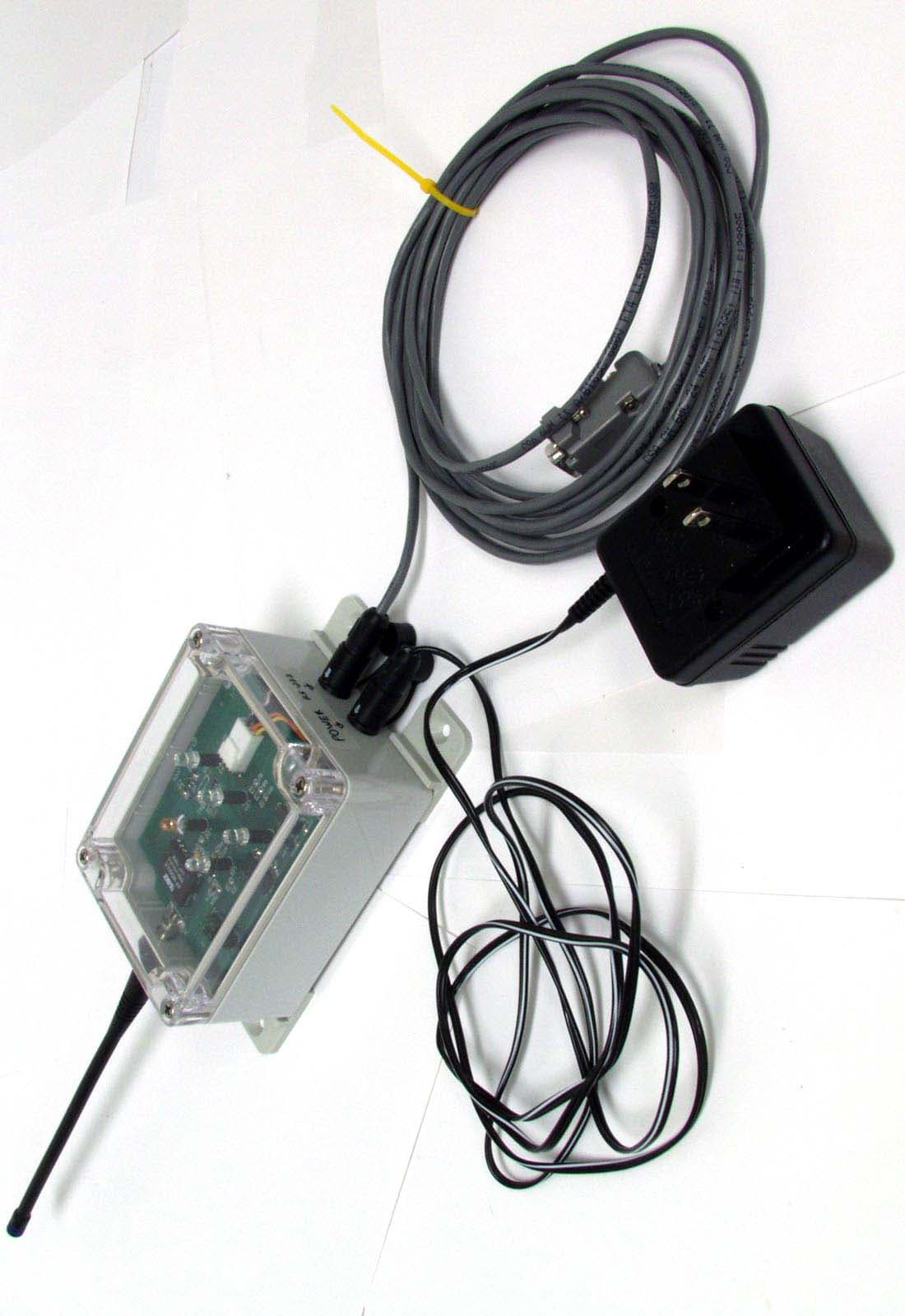
S4TSIG04182
Jul 06, 2005SIG04182
Equipment Class
CYY - Communications Receiver used w/Pt 15 Transmitter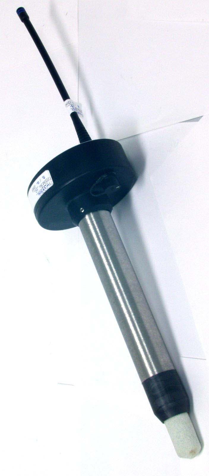
S4THOR04183
Jul 06, 2005HOR04183-P and HOR04183-M
Equipment Class
DXX - Part 15 Low Power Communication Device Transmitter