S5IELOCKSYSREM315Remote Garage Door Lock
Elocksys, Inc.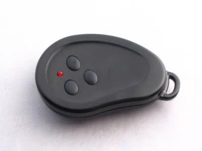
Click to zoom
Application Details
- Equipment Class
- DSC - Part 15 Security/Remote Control Transmitter
- Date of Grant
- May 10, 2005
- Application Purpose
- Original Equipment
- Date of Application
- May 10, 2005
- Equipment Note
- Remote Garage Door Lock
- Frequency Range
- 315.00000000 - 315.00000000
- Company
- Elocksys, Inc.
- Country
- United States
Documents & Files
Document Text
Text extracted from the exhibit documents filed with the FCC. Open a document above to read the original.
Users Manual
Installation and Operating Guide for the garage door lock Pro-Series 135 A Random-Code Remotes allow secure wireless control of the locking system Note: Exterior Key Release, Pull Cable Kit, must be installed on single entry or vaulted garages. Introduction and Table of Contents Read these instructions completely prior to installation, pay special attention to WARNINGS, CAUT IONS and order of installation steps. Make sure your garage door and operator are in good working order prior to lock installation. T he first section of this instruction manual covers lock-head installation on roll up garage doors. T he second section covers the changes to accommodate lock-head installation on one piece doors. Refer to steps 1, 2, 3, 7, ,9, 13, 14, 15 and 16 in the first section for one piece door installs. T he figures in this instruction manual are in order according to the steps. However you may need to review some figures out of order, as a reference to help execute the task at hand correctly. Table of contents: Introduction 1 Required T ools 3 Page 1 Hardware Kit Contents 4 Unpacking & Layout 5 Preparing Door Operator6 Warning Sheet 7 Preparing Door 8 Marking Door For Correct Lock-Head Position9 Mounting T he First Lock-Head 10 Routing wire.17 Mounting T he Second Lock-Head11 Fastening Wire Cable to Door 12 Making Receiver Holes In T rack 13 Installing Red L.E.D. 14 LED Install T hrough Door Panel 15 Mounting Plastic Bracket T o T rack 16 Suspending Wire Harness From Header to Operator18 Mounting Electrical Control Box 19 Mounting Magnetic Door Switch. 20 Powering Up.25 T his Section Is For One Piece Doors ONLY 21 How T o Mount Lock-Head (A) and (B) On a One Piece Door. 22 23 Metal Wire Harness Bracket For One Piece Doors One Piece Door Magnetic Switch Installation24 How T o Change Batteries30 Warranty Limitations and Guidelines 31 Troubleshooting 32 S econd section for one piece garage doors Operating Instructions Learning and Unlearning the Remotes to the Control Box. 26 Activating and Deactivating Auto Close and Lock Feature. 27 Safety,Warnings and Cautions2 Replacement Parts and Accessories29 Power out manually operating lock 28 Safety,Warnings and Cautions Page 2 IMPORTANT INSTALLATION INSTRUCTION ! WARNINGS ! To reduce the risk of severe injury or death: 1. READ AND FOLLOW ALL INSTALLATION WARNINGS AND INSTRUCTIONS 2. Install garage door lock only on properly balanced and lubricated garage door. An imp roperly balanced door may not reverse when required and could result in SEVERE INJURY or DEATH. 3. All rep airs if needed, to cables, sp ring assemblies and other hardware MUST be made by a trained door sy stems technician BEFORE installing the lock. 5. NEVER wear watches, rings or loose clothing while installing or servicing lock or operator. They could be caught in garage door, lock, or operator mechanisms. 4. NEVER connect garage door lock to power source until instructed to do so. 6. To prevent p ossible SERIOUS INJURY or DEATH: ALWAYS call a trained door sy stems technician if garage door binds, sticks, or is out of balance. An unbalanced garage door may not reverse when required. 7. ONLY operate garage door lock and operator at 110VAC 60HZ to avoid malfunction and damage. 8. Without a p roperly working safety reversal sy stem, persons (particularly small children) could be SERIOUSLY INJURED or KILLED by a closing garage door. Safety,Warnings and Cautions 9. To prevent INJURY from p inching, Keep hands, and fingers away from the joints while installing and testing the lock sy stem on the garage door. 10. Review the SAFTEY GUIDE in the operator owners manual. While installing the GARAGE DOOR LOCK use common sense. If you are unclear on the instructions or if you do not feel comfortable installing the lock sy stem contact a qualified service technician. Page 3 FCC Guideline Changes or modifications not expressly approved by Elocksys, Inc. could void the user's authority to operate the equipment. This product has been tested and complies with the specifications for a Class B digital device, pursuant to Part 15 of the FCC Rules. These limits are designed to provide reasonable protection against harmful interference in a residential installation. This equipment generates, uses, and can radiate radio frequency energy and, if not installed and used according to the instructions, may cause harmful interference to radio communications. However, there is no guarantee that interference will not occur in a particular installation. If this equipment does cause harmful interference to radio or television reception, which is found by turning the equipment off and on, the user is encouraged to try to correct the interference by one or more of the following measures: Reorient or relocate the receiving antenna Increase the separation between the equipment or devices Connect the equipment to an outlet other than the receiver's Consult a dealer or an experienced radio/TV technician for assistance Required Tools Drill 5/64”, 1/8” Drill bit 5/16”, 3/8” Drill Bitts 7/16” Wrench ½” Wrench Side Cutters Pliers Pocket Phillip s screw driver Pencil #2 Phillip s screw driver Flat blade screw driver #2 Phillip s bit 16 foot tap e Measure M edium metal file Step Ladder Page 4 Hammer Hardware Kit Contents Plastic Magnet and Bracket #6 X ¾ inch pan head-Phillip s (use with #5 one hole strap s) Qty 7 #2 #12 X 3 inch pan head Phillip s mounting screws #1 Qty 4 One hole strap for wire cable Supp ort #7 Qty 13 #4 #8 X 2 inch screw hook Qty 1 #6 One hole strap for Magnetic Switch Qty 1 #15 Plastic control wire bracket #12 1” X ¼” 20 Bolt and flange nuts for Plastic wire bracket Qty 4 #9 Qty 1 Qty 1 #10 Stap les for securing wire Qty 1 #11 LED Socket Qty 10 #8 Qty 2 #13 Qty 10 7” Tie Strap 4” Tie Strap #14 Qty 10 ft Ny lon string Qty 10 #5 # 8 X 1 5/8” inch Dry wall screw Page 5 Unpacking & Layout Unpack contents from box taking extreme care not to bend or kink wire cable. Lay lock assembly on floor inside garage with door …
Text truncated - open the document above for the full version.
Block Diagram
1. The Product 1.1 Outline The RF keyfob transmitter is primarity used for remote garage door closing and locking/ unlocking and opening. It is part of a system which also includes an RF receiver. The receiver, which is located in the garage, recevies, demodulates and decodes the RF transmission from the keyfob. This decoded transmission controls the action of the lock as well as the garage door opener. 1.2 Appearance The keyfob consists of a black plastic case with rubberized buttons. The size is approximately 2.7” x 1.8” (69mm x 46mm). There is a single red LED visible to the user to provide feedback to the user that an RF transmission has been made. The LED also indicates a low battery condition to the user. 1.3 Transmission Format The signals transmitted from the keyfob are encoded using PWM, employing 66 bits of data, with a modulation frequency of 833Hz and 100% amplitude modulation. 1.4 General Block Diagram Micro- Processor LED Power Cell 12VDC 5VDC Regulator Modulation and RF Stage Output Light Door Special Enable
ID Label/Location Info
SAMPLE LABEL FOR 2-PART STATEMENT - FCC Only FCC ID: S5IELOCKSYSREM315 Country Of Origin USA This device complies with Part 15 of the FCC Rules. Operation is subject to the following two conditions: 1) This device may not cause harmful interference and 2) This device must accept any interference that may be received, including interference that may cause undesired operation.
Operational Description
1. The Product 1.1 Outline The RF keyfob transmitter is primarity used for remote garage door closing and locking/ unlocking and opening. It is part of a system which also includes an RF receiver. The receiver, which is located in the garage, recevies, demodulates and decodes the RF transmission from the keyfob. This decoded transmission controls the action of the lock as well as the garage door opener. 1.2 Appearance The keyfob consists of a black plastic case with rubberized buttons. The size is approximately 2.7” x 1.8” (69mm x 46mm). There is a single red LED visible to the user to provide feedback to the user that an RF transmission has been made. The LED also indicates a low battery condition to the user. 1.3 Transmission Format The signals transmitted from the keyfob are encoded using PWM, employing 66 bits of data, with a modulation frequency of 833Hz and 100% amplitude modulation. 1.4 General Block Diagram Micro- Processor LED Power Cell 12VDC 5VDC Regulator Modulation and RF Stage Output Light Door Special Enable 2 Operating Instructions 2.1 Normal Operation In response to a single press of a button, the transmitter will send a single message for door/light or special. If a button is held, the transmitter will continuously transmit the message for up to approximately 20 seconds. The receiver ignores duplicate transmissions. 2.2 Test Modes None. 3 Operation Description 3.1 Idle Mode When no buttons are pressed, the 12VDC battery supplies a small standby current to the encoder chip, as well as a small current to the 5 VDC regulator. The regulator is disabled, so no power is supplied to the Modulation and RF stage. 3.2 Button Pressed When any button is pressed, the microprocessor encodes a PWM 66 bit message and transmitts the message to the RF stage. At the same time, the button enables the 5 VDC regulator, which turns on the 5 V supply to the Modulation and RF Stage. Once powered up the Modulation and RF Stage uses transmittes the data provided by the microprocessor. 3.3 Button Held As long as the button is held, the microprocessor will continue to transmit messages, up to a preset time limit. After approximately 20 seconds, the microprocessor will terminate transmission.
Parts List/Tune Up Info
Assy Report PartNoQtyLocation ELock Keyfob Remote V830014–7 Description 40104–531R1 RESISTOR 100KΩ 1/10W 40560–531R3 RESISTOR 56Ω 1/10W 0603 40682–533R2,R4,R5 RESISTOR 6.8KΩ 1/10W 53047–11U1 KEELOQ HCS301/SN SOIC 530531U3 VREG μPOWER 5V SOT23 530541U2 RADIO XMITTER SOIC 540272D1,D1 DUAL SWITCHING DIODES 540591D3 LED RED DIFF 540952C3,C6 CAP 0.1μF 16V Y5V 540961C5 CAP 100pF 50V COG 540971C4 CAP 4.7μF 10V Y5V M1206 541021X1 CRYSTAL ABRACON 541081C1 CAP 5.6pF NPO SM0402 541101C2 CAP 7.0pF NPO SM0402 541121C7 CAP 2.2μF 16V Y5V 580163SW1,SW2,SW3 SWITCH TACT 7MM SMD 60020–111PCB PCB Elock Keyfob V11 640172BATT TERM BATT Terminal 2/3/20051
Schematics
AA BB CC DD EE FF GG 1 1 2 2 3 3 4 4 5 5 Pacific Parallel Research, Inc. Notice of proprietary property. The information contained herein is the proprietary property of Pacific Parallel Research, Inc. The possessor agrees to the following: (i) To maintain this document in confidence. (ii) Not to reproduce or copy this document. (iii) Not to reveal or p ublish this document in whole or in p art. Title:Page:By: Created: Rev: Rev Date: of Craig Davidson 1 1 2/2/05 11/23/04 Remote 2.2 2.2 S3S2S1S0 VssPWM LEDVDD HCS30x 4321 56 7 8 HCS301/SL U1 REFOSCVssVDDPC SB ANTM ANTP ASK MICRF102BM 4321 5678 U2 3 1 2 BAV99ZXCT-ND D1 3 1 2 BAV99ZXCT-ND D2 SDTM-630-R SW1 SDTM-630-R SW2 SDTM-630-R SW3 D3 L1 SM0402 C1 5.6pF 50V 7pF 50VSM0402 C2 0.1μF 16V C3 SM0402 SM1206 4.7μF 10V C4 SM402 100pF 50V C5 0.1μF 16V C6 SM0402 SM0603 100K Ω R1 SM0603 R2 6.8K Ω 9.84375 MHz X1 +12V BAT1 +5V +5V 1 aJ1 2 bJ1 3 cJ1 4 dJ1 ENABGNDVIN NC VOUT LP2980 321 45 U3 2.2μF C7 R3 56 Ω SM0603 MMBT222A Q1 R4 SM0603 6.8K Ω R5 SM0603 6.8K Ω
Test Report
M. Flom Associates, Inc. 3356 N. San Marcos Place, Suite 107 Chandler, Arizona 85225-7176 FCC ID: S5IELOCKSYSREM315 (480) 926-3100 phone, fax (480) 926-3598 MFA p0530002, d0530040 Date: March 29, 2005 Federal Communications Commission Via: Electronic Filing Attention: Authorization & Evaluation Division Applicant: Elocksys, Inc. Equipment: Pro-Series 135 A (remote) FCC ID: S5IELOCKSYSREM315 FCC Rules: 15.231, Confidentiality Gentlemen: On behalf of the Applicant, enclosed please find Application Form 731, Engineering Test Report and all pertinent documentation, the whole for approval of the referenced equipment as shown. Filing fees are attached. We trust the same is in order. Should you need any further information, kindly contact the writer who is authorized to act as agent. Sincerely yours, David E. Lee, Compliance Test Manager enclosure(s) cc: Applicant DEL/ca M. Flom Associates, Inc. 3356 N. San Marcos Place, Suite 107 Chandler, Arizona 85225-7176 FCC ID: S5IELOCKSYSREM315 (480) 926-3100 phone, fax (480) 926-3598 MFA p0530002, d0530040 Transmitter Certification of FCC ID: S5IELOCKSYSREM315 Model: Pro-Series 135 A (remote) to Federal Communications Commission Rule Part(s) 15.231, Confidentiality Date of report: March 29, 2005 On the Behalf of the Applicant: Elocksys, Inc. At the Request of: P.O. Deposit Check #1004 Pacific Paralell Research, Inc. 922 Grange Hall Rd Cardiff By The Sea, CA 92007-1018 Attention of: Craig Davidson 760-436-6368 Email: [email protected] Supervised by: David E. Lee, Compliance Test Manager M. Flom Associates, Inc. 3356 N. San Marcos Place, Suite 107 Chandler, Arizona 85225-7176 FCC ID: S5IELOCKSYSREM315 (480) 926-3100 phone, fax (480) 926-3598 MFA p0530002, d053004040 List Of Exhibits (FCC Certification (Transmitters) - Revised 9/28/98) Applicant: Elocksys, Inc. FCC ID: S5IELOCKSYSREM315 By Applicant: 1. Letter Of Authorization 2. Identification Drawings Label Location of Label Compliance Statement Location of Compliance Statement 3. Documentation: 2.1033(B) (3) User Manual (4) Operational Description (5) Block Diagram (5) Schematic Diagram (7) Photographs Parts List Active Devices 4. Draft Specification Information By M.F.A. Inc. A. TESTIMONIAL & STATEMENT OF CERTIFICATION M. Flom Associates, Inc. 3356 N. San Marcos Place, Suite 107 Chandler, Arizona 85225-7176 FCC ID: S5IELOCKSYSREM315 (480) 926-3100 phone, fax (480) 926-3598 MFA p0530002, d053004040 The applicant has been cautioned as to the following: 15.21 Information to User. The users manual or instruction manual for an intentional radiator shall caution the user that changes or modifications not expressly approved by the party responsible for compliance could void the user's authority to operate the equipment. 15.27(a) Special Accessories. Equipment marketed to a consumer must be capable of complying with the necessary regulations in the configuration in which the equipment is marketed. Where special accessories, such as shielded cables and/or special connectors are required to enable an unintentional or intentional radiator to comply with the emission limits in this part, the equipment must be marketed with, i.e. shipped and sold with, those special accessories. However, in lieu of shipping or packaging the special accessories with the unintentional or intentional radiator, the responsible party may employ other methods of ensuring that the special accessories are provided to the consumer, without additional charge. Information detailing any alternative method used to supply the special accessories for a grant of equipment authorization or retained in the verification records, as appropriate. The party responsible for the equipment, as detailed in § 2.909 of this chapter, shall ensure that these special accessories are provided with the equipment. The instruction manual for such devices shall include appropriate instructions on the first page of text concerned with the installation of the device that these special accessories must be used with the device. It is the responsibility of the user to use the needed special accessories supplied with the equipment. M. Flom Associates, Inc. 3356 N. San Marcos Place, Suite 107 Chandler, Arizona 85225-7176 FCC ID: S5IELOCKSYSREM315 (480) 926-3100 phone, fax (480) 926-3598 MFA p0530002, d053004040 Table Of Contents Rule Description Page . Test Report 1 2.1033(c) General Information Required 2 . Standard Test Conditions and Engineering Practices 6 2.1046(a) RF Power Output (Radiated) 8 2.1053(a) Field Strength of Spurious Radiation 9 2.1049(c)(1) Emission Masks (Occupied Bandwidth) 13 M. Flom Associates, Inc. 3356 N. San Marcos Place, Suite 107 Page 1 of 14 Chandler, Arizona 85225-7176 FCC ID: S5IELOCKSYSREM315 (480) 926-3100 phone, fax (480) 926-3598 MFA p0530002, d053004040 Required information per ISO/IEC Guide 25-1990, paragraph 13.2: a) Test Report b) Laboratory: (FCC: 31040/SIT) (Canada: IC 2044) M. Flom Associates, Inc. 3356 N. San Marcos Place, Suite 107 Chandler, AZ 85225 c) Report Number: d0530040 d) Client: Pacific Paralell Research, Inc. 922 Grange Hall Rd Cardiff By The Sea, CA 92007-1018 e) Identification: Pro-Series 135 A (remote) FCC ID: S5IELOCKSYSREM315 Description: Garage door Lock remote f) EUT Condition: Not required unless specified in individual tests. g) Report Date: March 29, 2005 EUT Received: 2005-Feb-28 h, j, k): As indicated in individual tests. i) Sampling method: No sampling procedure used. l) Uncertainty: In accordance with MFA internal quality manual. m) Supervised by: David E. Lee, Compliance Test Manager n) Results: The results presented in this report relate only to the item tested. o) Reproduction: This report must not be reproduced, except in full, without written permission from this laboratory. M. Flom Associates, Inc. 3356 N. San Marcos Place, Suite 107 Page 2 of 14 Chandler, Arizona 85225-7176 FCC ID: S5IELOCKSYSREM315 (480) 926-3100 phone, fax (480) 926-3598 MFA p0530002, d053004040 List Of General Informati…
Text truncated - open the document above for the full version.
Test Setup Photos
FCC ID: S5IELOCKSYSREM315 MFA p0530002, d053004040 Test Setup: Radiated Emissions
Contact Information
Applicant
Bryan White
Technical Contact
M. Flom Associates, Inc.David Lee
[email protected]480-926-3100
3356 N San Marcos Place, Suite 107 · Chandler, Arizona · United States
Test Firm
Compliance Testing, LLCMichael Schafer
Technical Specifications
| # | Rule Parts | Frequency Range | Power Output |
|---|---|---|---|
| 1 | 15.231 | 315 MHz - 315 MHz | - |