S5J-TX01Security Transmitter
RGB Wireless Applications, Inc.
Click to zoom
Application Details
- Equipment Class
- DSC - Part 15 Security/Remote Control Transmitter
- Date of Grant
- Jun 09, 2005
- Application Purpose
- Original Equipment
- Date of Application
- Jun 09, 2005
- Equipment Note
- Security Transmitter
- Frequency Range
- 417.80000000 - 418.20000000
- Country
- United States
Documents & Files
Document Text
Text extracted from the exhibit documents filed with the FCC. Open a document above to read the original.
Users Manual
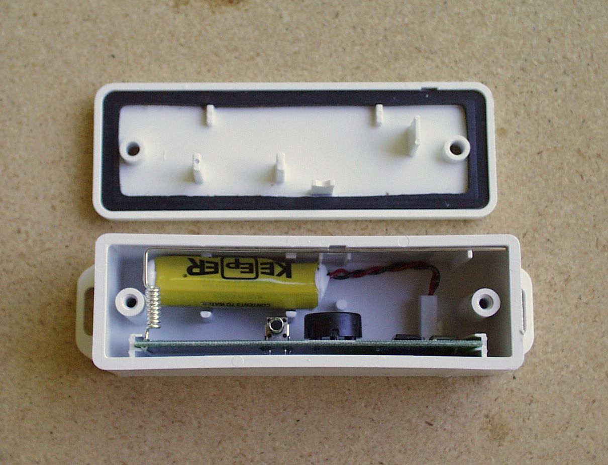
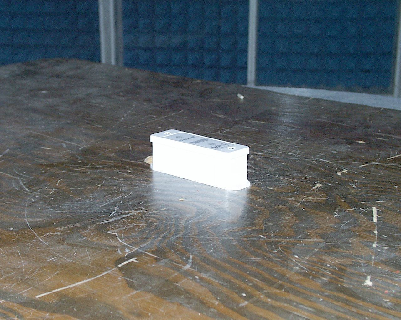
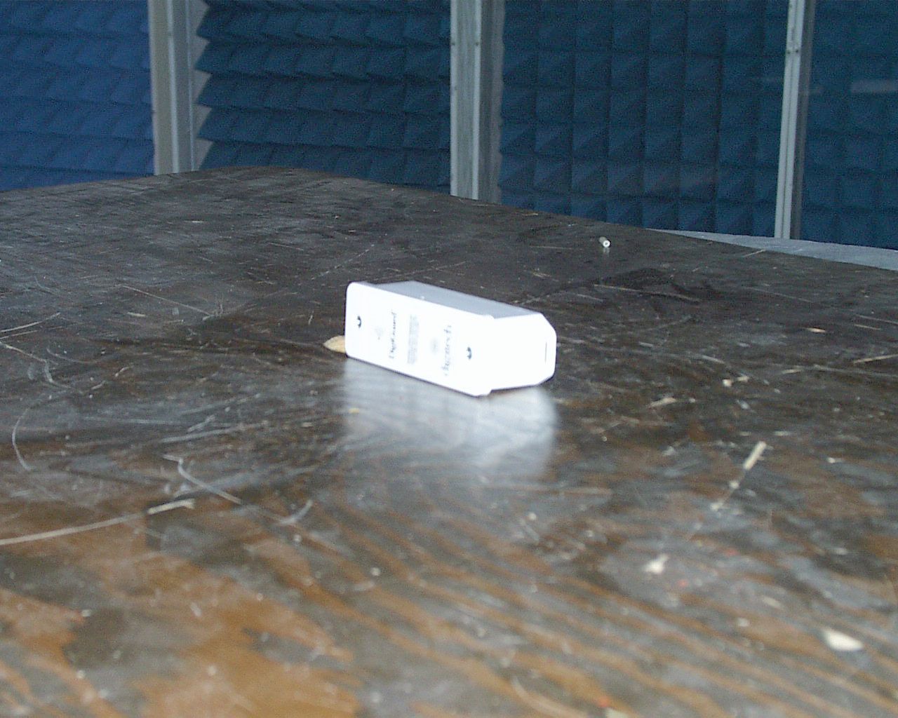
RGB Wireless Applications, Inc. DigiGuard™ Door Alarm Installation and Operation Guide DigiGuard™ Door Alarm Installation and Operation Guide COPYRIGHT Information in this document is subject to change without notice excluding the required FCC notices. No part of this publication may be reproduced, stored in a retrieval system, or transmitted in any form or any means electronic or mechanical, including photocopying and recording, for any purpose other than the purchaser’s personal use, without the written permission of RGB Wireless Applications, Inc. PUBLISHED BY RGB Wireless Applications, Inc © 2005 All Rights Reserved. No. 1200-182 Rev. 1.0 05/09/2005 Printed in the United States of America WARNING! This device operates under Part 15 of the FCC rules. Any modifications to this device not expressly authorized by RGB Wireless Applications, Inc. will void the user’s authority to operate this device. This device is not field serviceable and must be returned to the factory for any repairs. Please contact RGB Wireless Applications if any problems are experienced with this product. Warranty and Special Provisions LIMITED WARRANTY. Manufacturer warrants that the Software will perform substantially in accordance with the accompanying written materials for a period of three hundred sixty (360) days from the date of purchase. CUSTOMER REMEDIES. Manufacturer’s entire liability and your exclusive remedy shall be, at Manufacturer’s option, either (a) return of the price paid, or (b) repair or replacement of the Software that does not meet this Limited Warranty and which is returned to the Manufacturer with a copy of your receipt. This Limited Warranty is void if failure of this Software has resulted from accident, abuse, or misapplication. Any replacement Software will be warranted for the remainder of the original warranty period or thirty (30) days, whichever is longer. NO OTHER WARRANTIES. To the maximum extent permitted by applicable law, the Manufacturer and its suppliers disclaim all other warranties, either express or implied, including but not limited to implied warranties of merchantability and fitness for a particular purpose, with regard to the Software, the accompanying written materials, and any accompanying hardware. This Limited Warranty gives you specific legal rights. You may have others which vary from state/jurisdiction to state/jurisdiction. NO LIABILITY FOR CONSEQUENTIAL DAMAGES. To the maximum extent permitted by applicable law, in no event shall Manufacturer or its suppliers be liable for any damages whatsoever (including without limitation, direct or indirect damages for personal injury, loss of business profits, business interruptions, loss of business information, or any other pecuniary loss) arising out of the use of or inability to use this product, even if Manufacturer has been advised of the possibility of such damages. In any case, Manufacturer’s and its suppliers’ entire liability under any provision of this agreement shall be limited to the amount actually paid for the Software. Because some states/ jurisdictions do not allow the exclusion or limitation of liability for consequential or incidental damages, the above limitation may not apply Terms and Conditions of Purchase PURCHASER understands that unless otherwise specified in writing and agreed to by both parties, neither installation nor the warranty thereof, is included in this Agreement. Figure 1-2 Pre-Installation Considerations Site Design and Placement of Devices Planning must be done to ensure that all Door Transmitters can communicate with at least one Repeater or the Receiver. Repeaters are used to capture signals that cannot reach the Receiver directly. The Receivers and Repeaters are powered by 12VDC. The Door Transmitters use a lithium battery with a ten year calculated battery life. Each Door Transmitter is uniquely numbered and marked with a Serial Number on the back of the case. As each Transmitter is installed, the Serial Number MUST be recorded in conjunction with the Unit number it is installed on. This information will be required to set up the DigiGate- 700™ software for correct reporting. Door Transmitters are normally mounted in the upper left corner of the door or on the opposite side of the frame from the door latch. Repeaters can be mounted inside or outside of the building, depending on the unit door locations. Each Repeater requires 120/240 VAC power. The Repeaters should be mounted so the antenna is at approximately the same height or slightly above the Door Transmitters. This provides the best coverage of the facility, and requires the least number of Repeaters for the installation. The Receiver communicates with the System Controller over an RS-485 communication line. Normally the Receiver would be located in or near the office. Included in this Chapter Introduction.....................................................................Description of Door Transmitter Mounting the Door Transmitter and Magnet...................... Roll-Up Doors Garage Type Panel Roll-Up Doors Swing Doors Battery Connection and Replacement ........................ Installing the Battery Replacing the Battery Introduction The Door Transmitter, Figure 2-1, is housed in an environmental plastic enclosure. The enclosure has been designed for outdoor use, and has a UV inhibitor in the material. The enclosure is also moisture sealed with a gasket between the cover and case of the enclosure. The Door Transmitter is equipped with a tamper switch. Removing the cover of the Transmitter or placing another magnet near the case will trigger the tamper alarm. The Transmitter must be mounted on the door frame with the Magnet, Figure 2-2, mounted on the door. The proper alignment of these two components will ensure that the reed switch array will operate correctly when the door is opened and the Magnet moves away from the Transmitter. Proper orientation of the door switch will also ensure that the antenna is oriented corre…
Text truncated - open the document above for the full version.
Cover Letter(s)
RGB WIRELESS APPLICATIONS, INC. 8103 Lee Jackson Circle – Spotsylvania, VA 22553 June 2, 2005 Federal Communications Commission Authorization and Evaluation Division Confidentiality Request regarding application for certification of FCC ID: S5J-TX01. Pursuant to Sections 0.457 and 0.459 of the Commission’s Rules, we hereby request confidential treatment of certain information accompanying this application as outlined below: • Schematics • Circuit description • Block diagram The above documents contain information not normally released to the public. The public disclosure of these materials may be harmful to the applicant’s business and would provide unjustified benefits to it’s competitors. The applicant understands that pursuant to Section 0.457 of the Rules, disclosure of this application and all accompanying documentation will not be made before the date of the grant for this application. Sincerely, Patricia J. Greene Chief Financial Officer RGB Wireless Applications, Inc.
Test Report
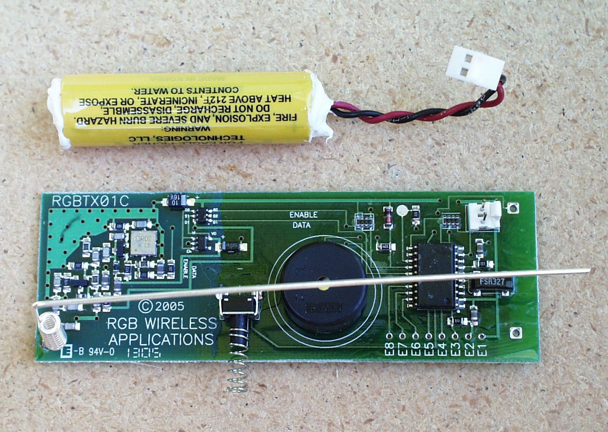
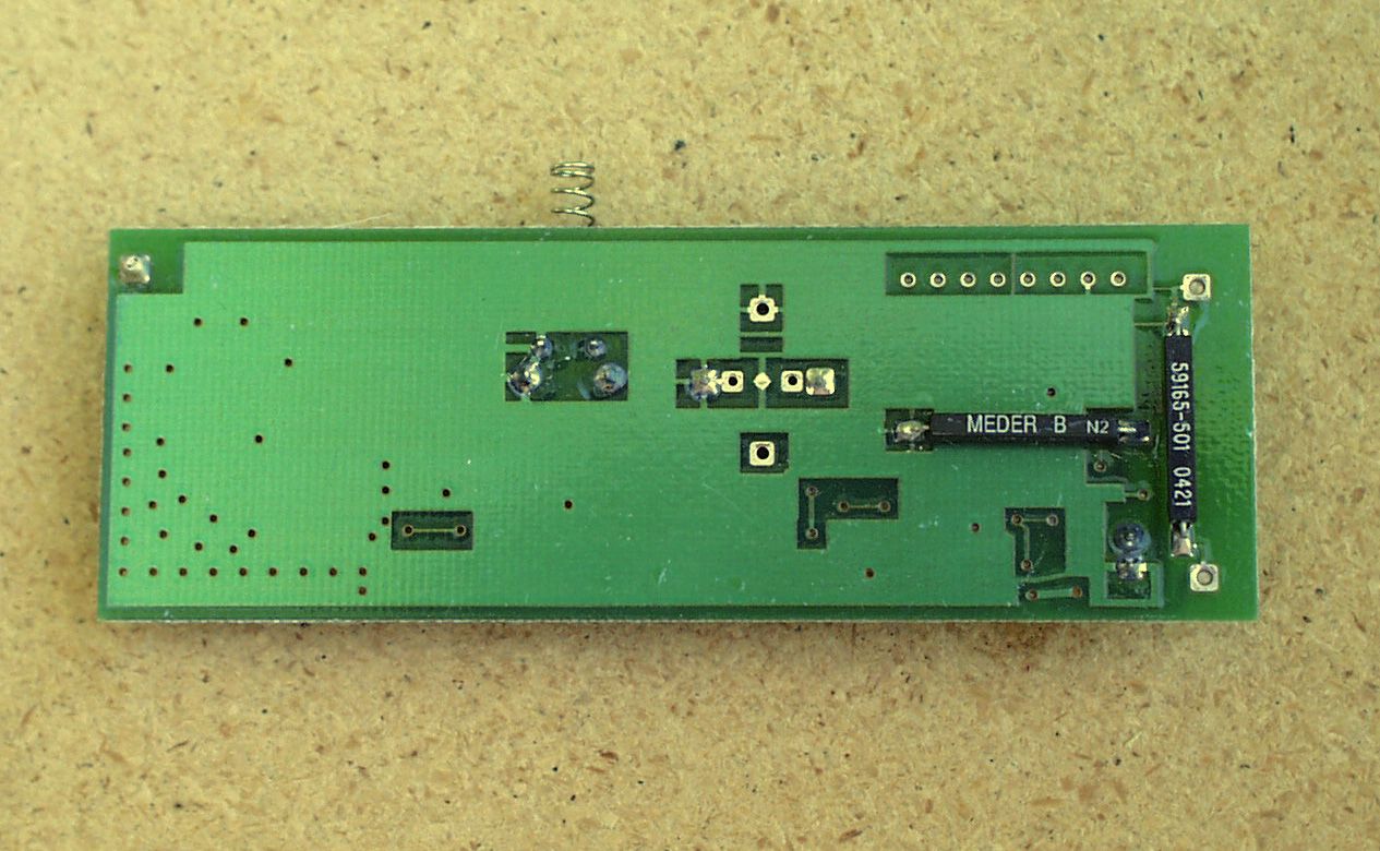
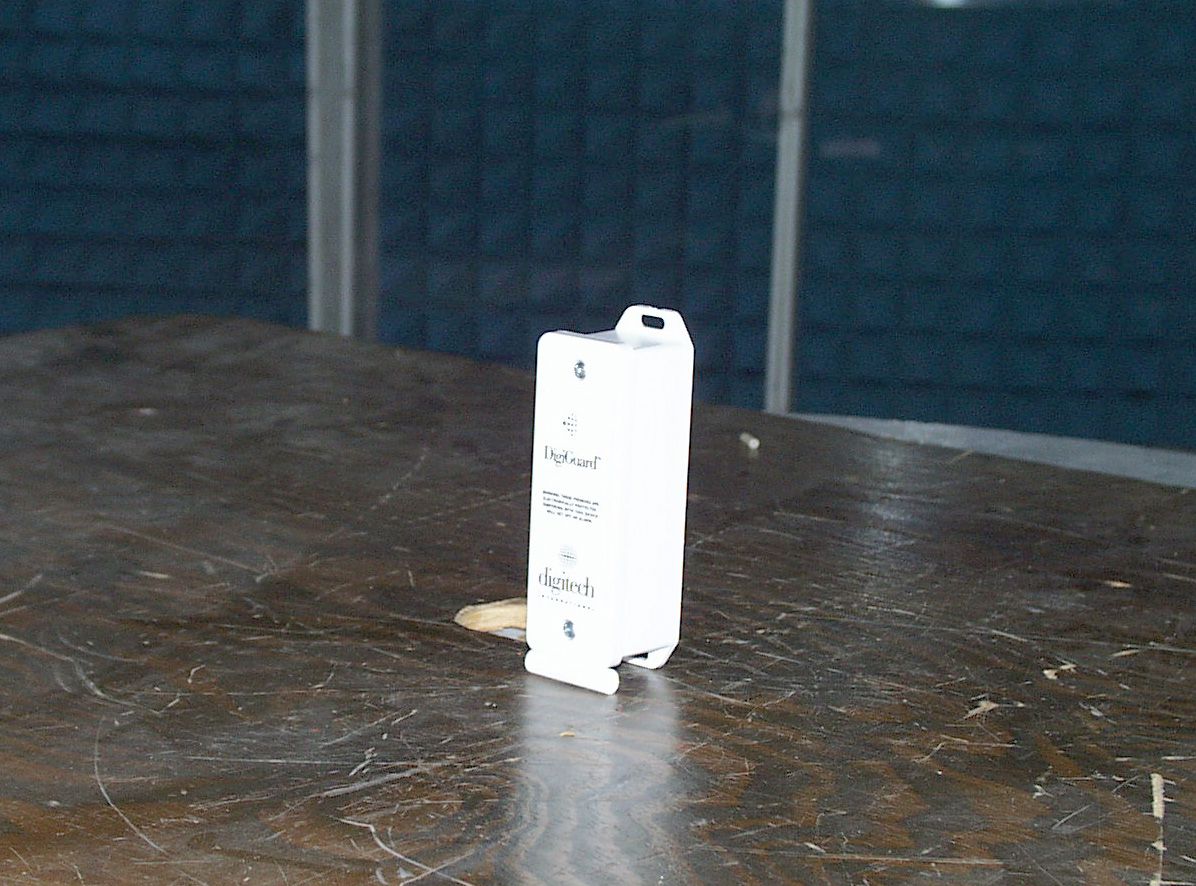
S5J-TX01 RGB Wireless Applications 1 Test Report of an intentional radiator under Part 15 of the FCC rules prepared for: RGB Wireless Applications, Inc. DigiGuard Transmitter FCC ID: S5J-TX01 DUT: Security Transmitter Model: TX01 Test Date: April 12, 2005 Manufacturer: RGB Wireless Applications, Inc. 8103 Lee Jackson Circle Spotsylvania, VA 22553 (540) 786-0621 Conducted by: Control Design & Testing, Inc. 6010 Red Fox Drive Spotsylvania, VA 22553 (540) 582-2826 Facility: Carl T Jones Corporation 7901 Yarnwood Court Springfield, VA 22153 FCC Site #90490, IC Site #3101 S5J-TX01 RGB Wireless Applications 2 CD&T FCC ID: S5J-TX01 A. DEVICE UNDER TEST The product is a security transmitter intended for the self storage industry to monitor the state of the roll-up doors that are typical of self storage facilities. This product is designed to operate under the provisions of Part 15.231 of the FCC rules. The transmit frequency is 418.00 MHz., nominal. The modulation mode is on/off keyed using Manchester Phase encoding at 4800 baud. Power for the device is provided by an internal “AA” size 3.6 volt lithium battery. The circuit is contained in a plastic housing and is weather sealed by a custom molded silicone gasket compressed between the case body and the case lid. The radio section is a two stage discrete circuit that employs a SAW resonator as the frequency determining element. The frequency tolerance is ± 200 KHz. The device employs a low power micro-controller, clocked at 32.368 KHz. to monitor input sensing and generate the transmission data. The rf circuitry and the modulation input are both regulated a 2.5 volts to insure level output power over the life of the battery. The antenna is a beryllium-copper loaded ¼ wave wire, custom manufactured for this product and is soldered directly to the printed circuit board. There is no provision to connect an external antenna. B. MEASUREMENT PROCEDURE: RADIATED EMISSIONS Testing of this device was conducted at the Carl T. Jones test facility located in Springfield, Virginia. FCC Site #90490, IC #3101. Transmitter field strength measurements were conducted according to the procedures set forth in ANSI C63.4 (1992). The device under test was placed on a rotating turntable 0.8 meters high, centered at three meters distant from the measurement antenna. The device was placed in the center of the turntable and tested in the positions shown in the test setup photographs. Testing was conducted with a fresh battery and monitored periodically to insure that the battery voltage (under load) was maintained at 90% of nominal or greater. However, the rf output of this device is regulated and will remain constant down to 2.65 volts at the battery. S5J-TX01 RGB Wireless Applications 3 For the purpose of radiated emissions testing, the sample was programmed to issue a constant pulse stream of alternating “1’s” and “ 0’s” at 4800 baud. The occupied bandwidth (Plot 1) was captured using a repeating stream of typical data packets, also at 4800 baud. The occupied bandwidth limit for this frequency is 1.045 MHz. Plot 1 S5J-TX01 RGB Wireless Applications 4 The field strength measurements were taken using an HP8596E spectrum analyzer, an EMCO 3121C dipole set, an EMCO 3115 double ridge guide horn. The device was scanned from 30 MHz. to 5 GHz. and all emissions were noted. In this case, the only emissions detected were those harmonically related to the fundamental of the transmit frequency. There is a 32.768 KHz. clock crystal associated with the micro-controller but no emissions related to the micro-controller or its clock could be identified in the screen room or on the OATS setup. At each detected emission frequency, the DUT was measured by rotating the turntable and adjusting the antenna height over a range of 1 to 4 meters to obtain the maximum output level. This procedure was performed with both horizontal and vertical antenna polarizations in all three positions shown in the setup photographs. The peak reading for each frequency was recorded in the fourth column in Table 1 below. The duty cycle corrected level is recorded in the seventh column. Measurements taken for weak emissions were performed by reducing the distance from the measurement antenna to 1 meter and factoring –9.54dB into the calculation. This method was used for the 9 th harmonic. CLIENT: RGB WIRELESSFCC ID: S5J-TX01 EUT: SECURITY TRANSMITTER PART 15.231DATE: 07-DEC-04 Ant. Polar. H/V 418.030V22.7-33.1920.066911669110333 836.060V30.2-74.3820.013841381033 1254.090H27.6-80.6420.0499501033 1672.120H29.3-85.2720.035636500 2090.150V31.0-91.4120.0214211033 2508.180V32.2-94.1120.0180181033 2926.210H33.6-96.0920.0168171033 3344.240V34.9-97.1820.0172171033 3762.270V36.1-101.8320.011612500 Table 1 RADIATED EMISSIONS DATA Frequency In MHz. Peak Power uV/m@3m Peak reading dBm Ant. Factor dB ANTENNA: DIPOLES/DRG HORN Duty Cycle -dB FCC Limit uV/m@3m Corrected Power uV/m@3m S5J-TX01 RGB Wireless Applications 5 C. DUTY CYCLE AND INTERVAL CALCULATIONS The occupied bandwidth and duty cycle measurements were made using an HP-8594E spectrum analyzer and plotted with an HP-7475A pen plotter. The computation for the duty cycle correction factor for column five in Table 1 is derived from the manufacture’s description of the data scheme and is verified by plots 2 through 7 below. The device transmits five packets every 28 minutes for system integrity and battery status but otherwise, it only transmits upon activation of the reed sensors or the tamper switch. The data format is a modified Manchester phase pulse modulation scheme. Each data packet consists of a start pulse of 968μs followed by a dead space of 1.76ms and then 32 pulses (32 * 208μs = 6.656ms) in Manchester Phase at 4800. This yields a total on time of 7.624ms per packet. Upon activation, 10 packets are transmitted at an interval greater than 100ms according to the formula: packet repeat interval time = (102.4ms + (serial number X random number in μs, between 1 an…
Text truncated - open the document above for the full version.
Contact Information
Applicant
Patricia Greene(CFO)
Test Firm
Timco Engineering, Inc.S Sanders
Technical Specifications
| # | Rule Parts | Frequency Range | Power Output |
|---|---|---|---|
| 1 | 15.231 | 417.8 MHz - 418.2 MHz | - |