S6F64RW9401Receiver of Care Phone
Tunstall Group AB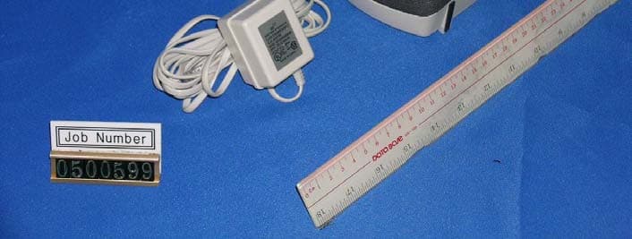
Click to zoom
Application Details
- Equipment Class
- CYY - Communications Receiver used w/Pt 15 Transmitter
- Date of Grant
- Sep 06, 2005
- Application Purpose
- Original Equipment
- Date of Application
- Sep 06, 2005
- Equipment Note
- Receiver of Care Phone
- Frequency Range
- 906.00000000 - 924.00000000
- Company
- Tunstall Group AB
- Country
- Sweden
Documents & Files
Document Text
Text extracted from the exhibit documents filed with the FCC. Open a document above to read the original.
Users Manual
1 General The Attendo Classic Care Phone is one of the products developed by Attendo Systems to give extra security and reassurance in the home. You can contact someone quickly and easily via the Attendo Classic Care Phone. Just press the alarm button to send an alarm to an alarm control center or to a friend or relative at home. Once the alarm has been acknowledged by the alarm receiver, a loudspeaking call will be connected and you can speak directly to the person at the alarm receiver. An alarm can be activated with the red alarm button on the Care Phone or with the Attendo Carry portable trigger. Several portable triggers can be used with the same Care Phone. Pressing the por- table trigger automatically performs a battery test. A battery alarm is sent to the alarm receiver if the battery is in poor condition. The Attendo Classic Care Phone can be wall-mounted or stand on a table. The Care Phone is easy to install and is connected to a telephone jack. The power supply is via a mains adapter to be inserted in an ordinary 110 V wall socket For extra security, the Attendo Classic is battery-powered in the event of power failure. The backup operation time is at least 24 hours with the supplied rechargeable battery pack. 2 The following articles are included in the Care Phone package: • Attendo Classic Care Phone including accumulator batteries. • Attendo Carry portable alarm trigger • Wrist strap • Neck cord • Mains adapter • Telephone line cord with RJ11C connectors in each end. • Operating instructions Loudspeaker Reset button (Green) Alarm button (Red) Lamp (LED) Removeable lid Microphone Your Attendo Classic Care Phone 3 Carry portable triggers may be worn on the wrist like a watch or around the neck like a neklace. The portable trigger is waterproof to a depth of 3 feet. Mains adapter Always leave the mains adapter in the wall socket, even if you go away. Attendo Carry portable trigger If necessary, you can wipe the Care Phone with a slightly damp cloth. 4 Press either your portable trigger ... ... or the red alarm button on the Care Phone. How to give the alarm 5 After giving the alarm After you have pressed the alarm button, the Care Phone will automatically call the alarm receiver at the following place/location: You will receive a reply after a short time, and you can then talk to the staff. It makes no difference where you are in the room. 6 Attendo Classic in operation Security The Attendo Classic Care Phone is one of the products Attendo Systems has developed to provide extra security in the home. Attendo Classic is intended primarily for individual living situations. Quick and easy contact With the Attendo Classic Care Phone it is quick and easy to get in touch with someone. A press of the alarm trigger sends an alarm to an alarm receiver or to the home of a friend or relative. When an alarm receiver acknowledges the alarm, a loudspeaking call is connected and the person sending the alarm may speak directly to the person with the alarm receiver. Activating the alarm A social alarm can be activated either by pressing the red button on the Care Phone or by pressing the button on the Attendo Carry portable alarm trigger. Other types of alarms can be activated by ancillary equipment such as a smoke detector. Alarm transmitters Up to 4 radio alarm transmitters such as the Attendo Carry portable alarm trigger or other Attendo radio transmitter may be easily programmed to the Care Phone. When the button on the portable alarm trigger is pressed, a battery test is performed. If the battery is bad, a battery alarm is sent to the alarm receiver. 7 Connecting The Care Phone is easy to install and connection to the telephone system is normally made through an intermediate telephone plug to a telephone jack. The Care Phone intermediate telephone plug should be connected to the first telephone jack in the house/apart- ment to ensure proper operation even when another telephone hand- set is off the hook. Power supply is via a mains adapter inserted in an ordinary 110 V wall socket. Battery accumulator The Care Phone is delivered with an automatic recharge battery accumulator. With the use of an accumulator, the total reserve opera- ting time is 24 hours from total power loss until it ceases to function. After a battery alarm the accumulator does not need to be replaced, but the power supply must be restored so that the accumulator can be recharged. Drilling template for wall mounting The Attendo Classic Care Phone may be hung on a wall or placed on a table (for wall mounting see the drilling template below). We recommend screw size 4x30 mm for wall mounting. Distance 122 mm 4 mm 4 mm 9 Installation NOTE! The alarm trigger contains batteries that has to be be disposed of in an environmentally friendly way when used up. How to install the Care Phone 1. Disconnect the exist ing t elephone from the telephone jack. IMPORTANT! The Care Phone should be connected to the first incoming telephone jack in the house/apartment. 2. Insert the one of the modular connectors of the supplied telephone line cord into the connector marked LINE on the back of the Attendo Classic. Insert the other modular connector into the t elephone line wall socket. 10 3. Insert the plug for any existing telephone into the connector marked PHONE on the back of the Attendo Classic. Check for dial tone. 4. Connect the transformer's modular connector to the in- put on the Care Phone marked 9V AC and insert the trans- former in a mains outlet. 5. Move the switch to the ON position and check that the LED on Classic is functioning. If it is steady green, the Care Phone is OK. If the LED flashes red or green for an extended period, there is a problem with the unit. Contact your supplier for assistance. IMPORTANT! The power switch must always be turned OFF when the care phone is not connected to the power mains in order to save batteries. Indication of incorrect installation If there is some problem - such as faulty connection of the…
Text truncated - open the document above for the full version.
External Photos
INTERTEK TESTING SERVICES External Photos FCC ID: S6F64RW9401 external photos.pdf - 1 of 2 INTERTEK TESTING SERVICES External Photos FCC ID: S6F64RW9401 external photos.pdf - 2 of 2
Internal Photos
INTERTEK TESTING SERVICES Internal photos FCC ID: S6F64RW9401 internal photos.pdf - 1 of 6 Internal Photo - 1 Internal Photo - 2 INTERTEK TESTING SERVICES Internal photos FCC ID: S6F64RW9401 internal photos.pdf - 2 of 6 Internal Photo - 3 Internal Photo - 4 INTERTEK TESTING SERVICES Internal photos FCC ID: S6F64RW9401 internal photos.pdf - 3 of 6 Internal Photo - 5 Internal Photo - 6 INTERTEK TESTING SERVICES Internal photos FCC ID: S6F64RW9401 internal photos.pdf - 4 of 6 Internal Photo - 7 Internal Photo - 8 INTERTEK TESTING SERVICES Internal photos FCC ID: S6F64RW9401 internal photos.pdf - 5 of 6 Internal Photo - 9 Internal Photo - 10 INTERTEK TESTING SERVICES Internal photos FCC ID: S6F64RW9401 internal photos.pdf - 6 of 6 Internal Photo - 11
Operational Description
Attendo Classic Main PCBA Circuit Description U101 is telephone specific function MCU SH93P426, it performs Battery Management, Charging control, RF Receiver Module Control, Speakerphone IC control, Telephone Line inteface control and DTMF decoding/Encoding. U103 HT24LC04 is EEPROM for storing the telephone number. U102 G699 monitor the power supply voltage level for MCU. The Telephone Line Interface circuit is consisted of J201, J202, F201, D201, D204~D207, Q201~Q208. F201 and D201 performs the transient voltage suppression function; Q204, Q205 and U201-D performs the Ringing signal detect function; U201-A, U201-B and U201-C performes the telephone line state monitoring function; Q201, Q202 and Q203 performs the Hook On/Off control function; Q206, Q207, Q208 and their peripherals perform the Tx audio signal and Rx audio signal amplifying, echol cancelling. U301 U4082B, U303 MC34119 and their peripherals constitute the Speakerphone Duplexer circuit. U4082B is consisted of Audio Signal Level Detector of Tx and Rx, Attenuator and MIC AMP, it can switch between Tx path and Rx path according the audio signal level detected. MC34119 is audio AMP to drive speaker. D402~D405 and LM317MDT performs the AC input power supply rectifying and regulating. This is the powe supply for whole product and Battery charging circuit. Q401, Q402, U403-A, U403-B and their peripherals perform the Battery voltage level monitoring and battey re-charging. Once the low battery voltage level signal is sent to MCU, then MCU can control the charging circuit to charge the battery. The MCU will terminate the charging process once the battery high voltage level detected and charging timing is out. U402 XC6201T331, Q403 and Q404 performs the DC power supply control and distribution. U402 is LDO to provide Vcc for MCU circuit. Q403 and Q404 switch on or off the power supply for Speakerphone Circuit under the control of MCU. Attendo Classic RF Receiver Module Circuit Description U1 LP2985 is LDO to provide Vcc voltage for MCU ATTiny26L and RF transceiver IC CC1021. U2 CC1021 is the RF transceiver IC, it consists of below parts: z two stage LNA with gain controled externally; z Quadrature down converter, IF BPF and AMP; z VCO and quatrature divider; z PLL Loop and PLL controller; z Digital Demodulator. The external LNA consists BFG425W and it’s peripheral circuits. The SAW filter prevent interference and increase the EMS performance of the units. The antenna is a wire type quarter wave length antenna, it is permanently attached on RF Module. Crystal 14.7456MHz is for CC1021. MCU ATTiny26L performs the RF Transceiver control, it is also the interface with Main PCBA MCU. SmartRF ® CC1021 CC1021 Single Chip Low Power RF Transceiver for Narrowband Systems Applications • Low power UHF wireless data transmitters and receivers with channel spacings of 50 kHz or higher • 433, 868 and 915 MHz ISM/SRD band systems • AMR – Automatic Meter Reading • Wireless alarm and security systems • Home automation • Low power telemetry • Automotive (RKE/TPMS) Product Description CC1021 is a true single-chip UHF trans- ceiver designed for very low power and very low voltage wireless applications. The circuit is mainly intended for the ISM (Industrial, Scientific and Medical) and SRD (Short Range Device) frequency bands at 433, 868 and 915 MHz, but can easily be programmed for multi-channel operation at other frequencies in the 402 - 470 and 804 - 940 MHz range. The CC1021 is especially suited for narrowband systems with channel spacings of 50 kHz and higher complying with EN 300 220 and FCC CFR47 part 15. The CC1021 main operating parameters can be programmed via a serial bus, thus making CC1021 a very flexible and easy to use transceiver. In a typical system CC1021 will be used together with a microcontroller and a few external passive components. CC1021 is based on Chipcon’s SmartRF ® - 02 technology in 0.35 μm CMOS. Features • True single chip UHF RF transceiver • Frequency range 402 MHz - 470 MHz and 804 MHz - 940 MHz • High sensitivity (up to –112 dBm for 38.4 kHz and –106 dBm for 102.4 kHz receiver channel filter bandwidths respectively) • Programmable output power • Low current consumption (RX: 19.9 mA) • Low supply voltage (2.3 V to 3.6 V) • Very few external components required • Small size (QFN 32 package) • Pb-free package • Digital RSSI and carrier sense indicator • Data rate up to 153.6 kBaud • OOK, FSK and GFSK data modulation • Integrated bit synchronizer • Image rejection mixer • Programmable frequency • Automatic frequency control (AFC) • Suitable for frequency hopping systems • Suited for systems targeting compliance with EN 300 220 and FCC CFR47 part 15 • Development kit available • Easy-to-use software for generating the CC1021 configuration data • Fully compatible with CC1020 for receiver channel filter bandwidths of 38.4 kHz and higher Chipcon AS SmartRF ® CC1021 Datasheet (rev. 1.1), 2004-12-20 Page 1 of 93 SmartRF ® CC1021 Table of Contents 1. Abbreviations................................................................................................................4 2. Absolute Maximum Ratings.........................................................................................5 3. Operating Conditions...................................................................................................5 4. Electrical Specifications..............................................................................................5 4.1. RF Transmit Section............................................................................................6 4.2. RF Receive Section.............................................................................................8 4.3. RSSI / Carrier Sense Section............................................................................11 4.4. IF Section...........................................................................................................11 4.5. Crystal Oscillator Section.....…
Text truncated - open the document above for the full version.
Schematics
Classic Care Phone schematic V5.sch-1 - Thu Feb 17 17:19:02 200 5 Classic Care Phone schematic V5.sch-2 - Thu Feb 17 17:19:14 200 5 Classic Care Phone schematic V5.sch-3 - Thu Feb 17 17:19:16 200 5 Classic Care Phone schematic V5.sch-4 - Thu Feb 17 17:19:16 200 5 Classic Care Phone schematic V5.sch-5 - Thu Feb 17 17:19:17 200 5 5 5 4 4 3 3 2 2 1 1 DD CC BB AA Radio_REQ Radio_CLK Radio_DAT Vin RB_GND DAT DAT REQ CLK REQ PS EL PSEL CLK AVdd_pin23 AVdd_pin22 AVdd_pin18 AVdd_pin23AVdd_pin22AVdd_pin18 OUT OUTIN IN LNA_EN LNA _EN Vcc Vcc Vcc Vcc Vcc Vcc Vcc Vcc Vcc VccVccVcc Vin Vin Vcc Vin2 Vcc Vin Vcc Vcc Title SizeDocument NumberRev Date:Sheet of Attendo:XXX-YYYY-ZZ / HotSwap: 1184-3DS002-03 ASRB - US - EU A/06 Attendo Simplex Receiver Board (ASRB) - USA/EU A3 11Monday, August 23, 2004 Design by M.Nygård HotSwap AB < < <> > > N.M. Optional components N.M. (Optional components for testing) N.M. N.M. N.M. = Not Mounted N.M. N.M. N.M. N.M. C35 1u TP13 C22 33p C18 33p C13 10p J1Wire Antenna flea1 1 C40 100n TP12 T1 BFG425W R2 10k R710k C19 33p TP17 C43 100p R11 10k C8 10p R422k R2022k TP3 C17 33p C25 33p TP21 U6 PUMH1 2 5 6 3 1 4 TP23 TP1 C30 100p R10 82k R1822 C37 1n R3 68 R14 33 R1610 TP5 TP8 L1 BLM11A221S C33 1n TP10 R8 0 J2 Female Header 1 2 3 4 5 6 7 8 TP15 C38 1n TP26 C10 220p R21 4.7k U1 LP2985 Vin 1 on/off 3 Vout 5 ByPass 4 GND 2 C54 100n R13 100k R1718k R1210k R15 100k L7 15n C9 10p C2 2.2n C28 33p TP22 R5 10k TP25 C51 100n C15 33p T2 BC857C U9 alternative C26 33p C52 33p R610k U7 14.7456 MHz 1 42 3 L4 BLM11A221S C31 100n TP7 J3PCB Antenna 1 C20 18p TP20 U10 SAW 31 2 4 5 6 C11 10p TP27 L2 15n C50 33p C45 1n C34 1n L3 18n C47 8.2p C42 100p C16 10u C56 33p C48 3.3p C3 33p C6 10n C39 100n R1 3.3k L5 BLM11A221S TP14 C7 1u C4 56n U2 CC1021 PCLK 1 PDI 2 PDO 3 DGND 4 DVdd 5 DGND 6 DCLK 7 DIO 8 VC 24 AVdd 23 AVdd 22 RF_OUT 21 AVdd 20 RF_IN 19 AVdd 18 R_BIAS 17 PSEL 32 DVdd 31 DGND 30 AVdd 29 CHP_OUT 28 AVdd 27 AD_REF 26 AGND 25 LOCK 9 XOSC_Q1 10 XOSC_Q2 11 AVDD 12 AVDD 13 LNA_EN 14 PA_EN 15 AVdd 16 AGND 0 C21 18p R19150 TP9 t RT1 10k L8 8.2n C1 560p C49 10p C29 33p C24 33p TP6 C55 100n L6 3.9n TP16 TP4 U8 PUMD2 5 2 4 6 3 1 C23 33p C27 33p U5 ATTiny26L PB0 1 PB1 2 PB2 3 PB3 4 Vcc 5 GND 6 PB4 7 PB5 8 PB6 9 PB7 10 PA0 20 PA1 19 PA2 18 PA3 17 GND 16 AVcc 15 PA4 14 PA5 13 PA6 12 PA7 11 C53 100n TP24 C32 100n C4610p C5 2.2u C14 10p TP18 C44 1n TP2
Test Report
• The test results reported in this test report shall refer only to the sample actually tested and shall not refer or be deemed to refer to bulk from which such a sample may be said to have been obtained. • This report shall not be reproduced except in full without prior authorization from Intertek Testing Services Hong Kong Limited. • For Terms And Conditions of the services, it can be provided upon request. • The evaluation data of the report will be kept for 3 years from the date of issuance. Intertek Testing Services Hong Kong Ltd. 2/F., Garment Centre, 576 Castle Peak Road, Kowloon, Hong Kong. Tel: (852) 2173 8888 Fax: (852) 2371 0521 Website: www.hk.intertek-etlsemko.com Attendo AB Application For Certification (FCC ID: S6F64RW9401) Superheterodyne Receiver 0500599 TL/ Ann Choy July 15, 2005 INTERTEK TESTING SERVICES FCC ID: S6F64RW9401 i LIST OF EXHIBITS INTRODUCTION EXHIBIT 1: General Description EXHIBIT 2: System Test Configuration EXHIBIT 3: Emission Results EXHIBIT 4: Equipment Photographs EXHIBIT 5: Product Labelling EXHIBIT 6: Technical Specifications EXHIBIT 7: Instruction Manual EXHIBIT 8: Miscellaneous Information INTERTEK TESTING SERVICES FCC ID: S6F64RW9401 ii MEASUREMENT/TECHNICAL REPORT Attendo AB - MODEL: 64RW9401 FCC ID: S6F64RW9401 This report concerns (check one:) Original Grant X Class II Change _____ Equipment Type: CYY - Superheterodyne Receiver (example: computer, printer, modem, etc.) Deferred grant requested per 47 CFR 0.457(d)(1)(ii)? Yes No X If yes, defer until: date Company Name agrees to notify the Commission by: date of the intended date of announcement of the product so that the grant can be issued on that date. Transition Rules Request per 15.37? Yes No X If no, assumed Part 15, Subpart B for unintentional radiator - the new 47 CFR [12-08-03 Edition] provision. Report prepared by: Tommy Leung Intertek Testing Services Hong Kong Ltd. 2/F., Garment Centre, 576, Castle Peak Road, Kowloon, Hong Kong. Phone: 852-2173-8538 Fax: 852-2741-1693 INTERTEK TESTING SERVICES FCC ID: S6F64RW9401 iii Table of Contents 1.0 General Description .........................................................................................2 1.1 Product Description ............................................................................................2 1.2 Related Submittal(s) Grants ...............................................................................2 1.3 Test Methodology...............................................................................................3 1.4 Test Facility ........................................................................................................3 2.0 System Test Configuration ..............................................................................5 2.1 Justification ........................................................................................................5 2.2 EUT Exercising Software ...................................................................................5 2.3 Special Accessories ...........................................................................................5 2.4 Equipment Modification ......................................................................................6 2.5 Measurement Uncertainty ..................................................................................6 2.6 Support Equipment List and Description ............................................................6 3.0 Emission Results .............................................................................................8 3.1 Field Strength Calculation ..................................................................................9 3.2 Radiated Emission Configuration Photograph ..................................................10 3.3 Radiated Emission Data...................................................................................11 3.4 Conducted Emission Configuration Photograph ...............................................13 3.5 Conducted Emission Data................................................................................14 4.0 Equipment Photographs ................................................................................20 5.0 Product Labelling ...........................................................................................22 6.0 Technical Specifications ...............................................................................24 7.0 Instruction Manual .........................................................................................26 8.0 Miscellaneous Information ............................................................................28 8.1 Discussion of Pulse Desensitization .................................................................29 8.2 Calculation of Average Factor ..........................................................................30 8.3 Emissions Test Procedures..............................................................................31 INTERTEK TESTING SERVICES FCC ID: S6F64RW9401 iv List of attached file Exhibit type File Description filename Test Report Test Report report.pdf Operation Description Technical Description descri.pdf Test Setup Photo Radiated Emission config photos.doc Test Setup Photo Conducted Emission config photos.doc Test Report Conducted Emission Test Result conduct.pdf External Photo External Photo external photos.doc Internal Photo Internal Photo internal photos.doc Block Diagram Block Diagram block.pdf Schematics Circuit Diagram circuit.pdf ID Label/Location Label Artwork and Location label.pdf User Manual User Manual manual.pdf INTERTEK TESTING SERVICES FCC ID: S6F64RW9401 1 EXHIBIT 1 GENERAL DESCRIPTION INTERTEK TESTING SERVICES FCC ID: S6F64RW9401 2 1.0 General Description 1.1 Product Description The Equipment Under Test (EUT) is a Receiver of Social Care Phone operating at 906MHz, 915MHz, and 924MHz. The EUT is powered by 120VAC to 9VAC 500mA adaptor or 4.8V 1600mAh Ni-MH type rechargeable …
Text truncated - open the document above for the full version.
Test Report
Report No.: 0500599 Speakerphone On Mode Ctrl No.: N/A PAGE 1 Tested By:Hong, Report No.:0500599 Scan Settings (1 Range) |--------- Frequencies -----------||----------- Receiver Settings ------------| Start Stop Step IF BW Detector M-Time Atten Preamp OpRge 150k 30M 5k 10k PK+AV 10ms AUTO LN OFF 60dB Final Measurement: x QP / + AV Meas Time: 1 s Subranges: 16 Acc Margin: 20dB Transducer No. Start Stop Name 21 9k 30M EW0698 0 10 20 30 40 50 60 70 80 90 dBuV 100 0.15 MHz 30 110 F15Q F15A Report No.: 0500599 Speakerphone On Mode Ctrl No.: N/A Tested By:Hong, Report No.:0500599 Scan Settings (1 Range) |--------- Frequencies -----------||----------- Receiver Settings ------------| Start Stop Step IF BW Detector M-Time Atten Preamp OpRge 150k 30M 5k 10k PK+AV 10ms AUTO LN OFF 60dB Final Measurement Results: no Results
Test Setup Photos
INTERTEK TESTING SERVICES The Worst Case Configuration Photographs FCC ID : S6F64RW9401 config photos.pdf (radiated emission) - 1 of 1 Radiated Emission Front View Rear View INTERTEK TESTING SERVICES The Worst Case Configuration Photographs FCC ID : S6F64RW9401 config photos.pdf (conducted emission) - 1 of 2 Conducted Emission Front View Rear View INTERTEK TESTING SERVICES The Worst Case Configuration Photographs FCC ID : S6F64RW9401 config photos.pdf (conducted emission) - 2 of 2 Conducted Emission Side View
Contact Information
Applicant
Torbj�rn Eriksson
Technical Contact
Intertek Testing Services Hong Kong Ltd.Tommy Leung
[email protected]852-2173-8538
2/F., Garment Centre, · Kowloon · Hong Kong
Non-Technical Contact
Intertek Testing Services Hong Kong Ltd.Tommy Leung
[email protected]852-2173-8538
Test Firm
Intertek Testing Services Hong KongBilly Chow
Technical Specifications
| # | Rule Parts | Frequency Range | Power Output |
|---|---|---|---|
| 1 | 15B | 906 MHz - 924 MHz | - |
Other Applications from Tunstall Group AB
S6F64US9423
Sep 06, 2005Transmitter for Care Phone
Equipment Class
DXX - Part 15 Low Power Communication Device Transmitter