S7A-SP08-AMOTORCYCLE BLUETOOTH HEADSET & INTERCOM
Sena Technologies Co., Ltd.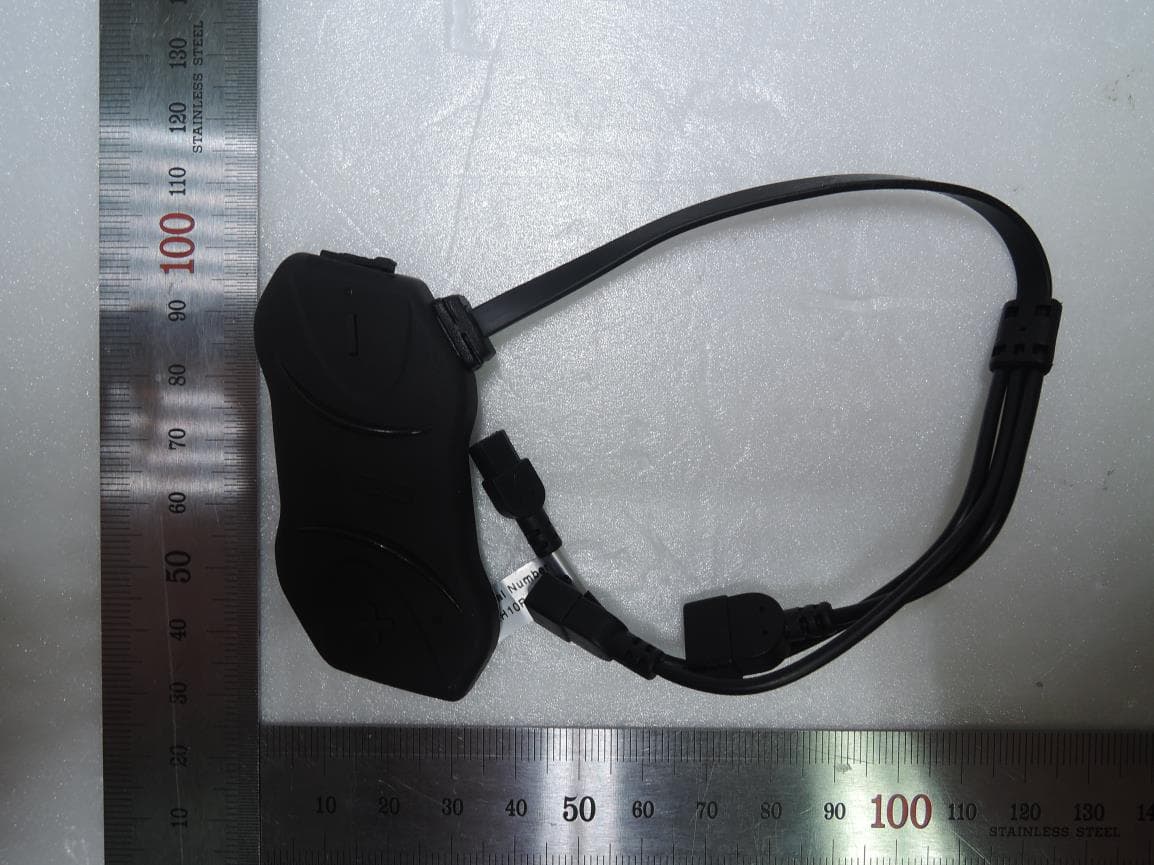
Click to zoom
Application Details
- Equipment Class
- DSS - Part 15 Spread Spectrum Transmitter
- Date of Grant
- Sep 30, 2015
- Application Purpose
- Original Equipment
- Date of Application
- Sep 30, 2015
- Equipment Note
- MOTORCYCLE BLUETOOTH HEADSET & INTERCOM
- Frequency Range
- 2402.00000000 - 2480.00000000
- Company
- Sena Technologies Co., Ltd.
- Country
- South Korea
Documents & Files
Document Text
Text extracted from the exhibit documents filed with the FCC. Open a document above to read the original.
Users Manual
| SMH10R 1 SMH10R Low Profile Motorcycle Bluetooth Headset & Intercom SENA www.senabluetooth.com User’s Guide | SMH10R 2 © 1998-2012 Sena Technologies, Inc. All rights reserved. Sena Technologies, Inc reserves the right to make any changes and improvements to its product without providing prior notice. Sena™ is a trademark of Sena Technologies, Inc. or its subsidiaries in the USA and other countries. SMH10™, SMH5™, SPH10™, SPH10S™, SPH10H™, SR10™, SM10™, SMH10R™ are trademarks of Sena Technologies, Inc. or its subsidiaries. These trademarks may not be used without the express permission of Sena. The Bluetooth® word mark and logos are owned by the Bluetooth SIG, Inc. and any use of such marks by Sena is under license. iPhone, iPod touch are registered trademarks of Apple Inc. Zumo™ is a trademark of Garmin Ltd. or its subsidiaries. TomTom™ is the trademark or registered trademark owned by TomTom International B.V. Other trademarks and tradenames are those of their respective owners. | SMH10R 3 CONTENTS 1. INTRODUCTION 2. PACKAGE CONTENTS 3, INSTALLING THE SMH10R ON YOUR HELMET 4. POWERING ON/OFF AND CHARGING 4.1 Powering On 4.2 Powering Off 4.3 Charging 4.4 Low Battery Warning 4.5 Checking the Battery Level 5. VOLUME ADJUSTMENT 6. SMH10 CONFIGURATION SETTING 6.1 Enabling/Disabling Voice Activated Phone Answering 6.2 Enabling/Disabling Voice Activated Intercom 6.3 Enabling/Disabling Voice Prompts 6.4 Enabling/Disabling PLC (Packet Loss Consealment) 6.5 Delete All Bluetooth Pairing Information 6.6 Exit Voice Configuration Menu 7. PAIRING THE SMH10R WITH BLUETOOTH DEVICES 7.1 Mobile Phone Pairing 7.2 Bluetooth Stereo Device Pairing 7.3 Bluetooth GPS Navigation Pairing 7.4 Pairing with the Sena SR10, Bluetooth Two-way Radio Adapter 8. PAIRING WITH SELECTIVE PROFILE: A2DP STEREO OR HANDSFREE 8.1 A2DP Stereo Music Only 8.2 HFP for Phone Call Only 9. INTERCOM PAIRING 9.1 Pairing with Other SMH10R Headsets for Intercom Conversation 9.2 Pairing with Other SENA Headset Models for Intercom Conversation 10. FUNCTION PRIORITY 11. STEREO MUSIC 11. 1 By Bluetooth Wireless Stereo 12. MOBILE PHONE CALL MAKING AND ANSWERING 13. TWO-WAY INTERCOM 13.1 Start and End Two-way Intercom 13.2 Intercom and Mobile Phone Call 13.3 Intercom and GPS 13.4 Intercom and Two-way Radio 14. THREE-WAY CONFERENCE INTERCOM 14.1 Start Three-way Intercom 14.2 End Three-way Intercom 15. FOUR-WAY CONFERENCE INTERCOM 15.1 Start Four-way Intercom 15.2 End Four-way Intercom 16. THREE-WAY CONFERENCE PHONE CALL WITH INTERCOM PARTICIPANT 17. INTERCOM FAILURE 18. INTERCOM RECONNECTION 19. FAULT RESET 20. FIRMWARE UPGRADE 21. CASE STUDY | SMH10R 4 BATTERY INFORMATION MAINTENANCE AND CARE DISPOSAL CERTIFICATION AND SAFETY APPROVALS FCC Compliance Statement FCC RF Exposure Statement FCC Caution CE Declaration of Conformity Industry Canada Statement Bluetooth License WAIVER AND GENERAL RELEASE Two -Year Limited Warranty Limitation of Liability Return for Full Refund WARNING | SMH10R 5 1. INTRODUCTION Thank you f or c hoosing t he S ena S MH10R, B luetooth S tereo H eadset an d I ntercom for s ports bi ke riders. W ith the SMH10R, you can call handsfree on your Bluetooth mobile phone, listen to stereo music or voice instructions of GPS navigations by Bluetooth wirelessly, and have intercom conversations in full duplex with a passenger or other sports bike riders. The SMH10R is compliant with the Bluetooth 3.0 supporting the following profiles: Headset Profile, Hands-Free Profile (HFP), Advanced Audio Distribution Profile (A2DP), and Audio Video Remote Control Profile (AVRCP). Please check with the manufacturers of other devices to determine their compatibility with this headset. Please r ead t his us er’s g uide c arefully before us ing the he adset. Also c heck www.senabluetooth.com/support for t he latest version of the user’s guide and additional information related to Sena Bluetooth products. The SMH10R features: ● Bluetooth handsfree for Bluetooth mobile phones ● Bluetooth stereo headset for Bluetooth audio devices such as MP3 players ● Bluetooth stereo headset for Bluetooth GPS navigations ● Bluetooth intercom up to 900 meters (980 yards) * ● Four -way conference intercom ● Three-way conference phone call with intercom participant ● Multipoint Bluetooth pairing with GPS navigation or Sena SR10 Two-way Radio Adapter ● Multipoint Bluetooth pairing for 2 mobile phones ● Ultra slim and feather light ● Firmware upgradeable * in open terrain Key Specifications: ● Bluetooth 3.0 ● Supporting profiles: Headset Profile(HSP), Hands-Free Profile (HFP), Advanced Audio Distribution Profile (A2DP), Audio Video Remote Control Profile (AVRCP) | SMH10R 6 2. PACKAGE CONTENTS Headset Main Unit (+) Button / (-) Button Volume adjustment Navigate through configuration menu Track-forward and track-back Center Button Answer and end a mobile phone call Reject an incoming mobile phone call Start and end intercom conversation Play and pause Bluetooth stereo device Enter into intercom pairing mode Enter into voice configuration setting DC Power Charging & Firmware Upgrade Port Speaker Connector (4 pin female type) Battery Pack Connector (2 pin male type) Microphone Connector (2 pin female type) | SMH10R 7 Speakers Attachable Boom Microphone Wired Microphone Battery Pack Speaker Pad Attachable Boom Microphone Holder Velcro Pad for Boom Microphone Velcro Pad for Speaker Velcro Pad for Boom Microphone Holder Velcro Pad for Wired Microphone Velcro Pads for Battery Pack Mounting Cradle Microphone Sponge USB Power & Data Cable 3. INSTALLING THE SMH10R ON YOUR HELMET To securely install the SMH10R on the helmet, please follow the procedure. 1 Locate a proper surface on the helmet to attach the Mounting Cradle, clean the helmet surface location with a moistened towel, and allow to drying thoroughly. 2 Adhere with double sided tape on the back side of the Mounting Cradle to the surface on the helmet. 3 Clamp the SMH10R main…
Text truncated - open the document above for the full version.
Attestation Statements
SENA TECHNOLOGIES.Inc 40, Maeheon-ro, Seocho-gu, Seoul, Korea. Sep 8 th , 2015 Applicant: SENA TECHNOLOGIES.Inc FCC ID: S7A-SP08-A IC: 8154A-SP08A The typical placement of the EUT is on a motorcycle helmet. See the photo on next page. The distance between the device and user in the worst case application, is 30mm. Seunghyun Kim Reasearch Engineer Inside Helmet
Cover Letter(s)
Sena Technologies,Inc. 210 Yangjae-dong Seocho-gu, Seoul, South Korea, 137-130 Date: Aug. 28, 2015 Timco Engineering, Inc. 849 N.W. State Road 45 P.O. Box 370 Newberry, Florida 32669 USA Letter of Authorization We, the undersigned, hereby authorize Harvey Sung of DT&C C o., Ltd. to act on our behalf in all manners relating to application for equipment authorization for FCC ID: S7A-SP08-A including signing of all documents relating to these matters. Any and all acts carried out by Harvey Sung of DT&C C o., Ltd. on our behalf shall have the same affect as acts of our own. This authorization is valid until further written notice from Sena Technologies,Inc. “I, the undersigned, hereby certify that we are not subject to a denial of federal benefits, that includes FCC benefits, pursuant to Section 5301 of the Anti-Drug Abuse Act of 1988, 21 U.S.C. 853(a).” Sincerely, Seunghyun KIM Reasearch Engineer
Cover Letter(s)
Sena Technologies,Inc. 210 Yangjae-dong Seocho-gu, Seoul, South Korea, 137-130 Date: Aug. 28, 2015 Timco Engineering, Inc. 849 N.W. State Road 45 P.O. Box 370 Newberry, Florida 32669 USA RE: Request of Confidentiality for FCCID: S7A-SP08-A To Whom It may Concern: Pursuant to Sections 0.457 and 0.459 of the Commission`s Rules(CFR 47), and Section 552 (b) (4) of the Freedom of Information Act, Sena Technologies,Inc. hereby requests confidentiality and treatment of certain information accompanying this application. The materials contain trade secrets and proprietary information not customarily released to the public. The public disclosure of these matters might be harmful to the Applicant and provide unjustified benefits to its competitors. We are also hereby request Short-Term Confidentiality for 180 days after the grant as outlined in Public Notice DA 04-1705. This provision will give Sena Technologies,Inc. temporary confidentiality of commercially sensitive information prior to product release. The requested permanent and Short-Term Confidential exhibits are listed as follows: PERMANENT & SHORT-TERM CONFIDENTIAL LIST Exhibit Description PERMANENT 1 Block Diagram 2 Schematics 3 Operational Description 4 Part Lists SHORT-TERM 5 External Photos 6 Internal Photos 7 Test-Setup Photos 8 User Manual The Applicant understands that pursuant to Rule 0.457, disclosure of this application and all accompanying documentations, where applicable, will not be public before the date of the Grant for this application. Sincerely, Seunghyun KIM Reasearch Engineer
Cover Letter(s)
Sena Technologies,Inc. 210 Yangjae-dong Seocho-gu Seoul 137-130 Korea Date: Aug. 28, 2015 Timco Engineering, Inc. 849 N.W. State Road 45 P.O. Box 370 Newberry, Florida 32669 USA DECLARATION FOR ADDITIONAL FREQUENCY HOPPING REQUIREMENTS T o whom it may concern: We hereby declare that the device of (FCC ID: S7A-SP08-A, IC: 8154A-SP08A) meet following FCC requirements of the Section 15.247(a)(1) : 1.The hopping sequence is pseudorandom. 2.All channels are used equally on average. 3.The receiver input bandwidth approximately equal the transmit bandwidth. 4.The receiver hop in sequence with the transmit signal. Sincerely, Seunghyun Kim Reasearch Engineer
External Photos
FCC ID: S7A-SP08-A IC: 8154A-SP08A Copyright Ⓒ 2015, DT&C Co., Ltd. Page 1 / 3 View 1 FCC ID: S7A-SP08-A IC: 8154A-SP08A Copyright Ⓒ 2015, DT&C Co., Ltd. Page 2 / 3 View 2 FCC ID: S7A-SP08-A IC: 8154A-SP08A Copyright Ⓒ 2015, DT&C Co., Ltd. Page 3 / 3 View 3
ID Label/Location Info
FCC ID: S7A-SP08-A Copyright Ⓒ 2015, DT&C Co., Ltd. FCC & IC ID SAMPLE LABEL & LOCATION LABELLING REQUIREMENTS PER §2.925 The Label shown shall be permanently affixed at a conspicuous location on the device and be readily visible to the user at the time of purchase Label Location - The FCC label shown is representative of the label that will appear on the radio when in production. Other information may also be included on this label. - The device is so small that it is not practicable to place the statement specified under 15.19 statement request, the information required by this paragraph shall be placed in a prominent location in the user's manual.
Internal Photos
FCC ID: S7A-SP08-A IC: 8154A-SP08A Copyright Ⓒ 2015, DT&C Co., Ltd. View 1 FCC ID: S7A-SP08-A IC: 8154A-SP08A Copyright Ⓒ 2015, DT&C Co., Ltd. View 2 FCC ID: S7A-SP08-A IC: 8154A-SP08A Copyright Ⓒ 2015, DT&C Co., Ltd. View 3
RF Exposure Info
MHzmm = Typical Power: ± =[ / ]*[√ ] = Thus SAR for this device is not required. [Threshold at 50 mm in step 1) + (test separation distance - 50 mm)·( f(MHz)/150)] mW [Threshold at 50 mm in step 1) + (test separation distance - 50 mm)·10] mW 30 Step 2-1) SAR test exclusion thresholds for 100MHz to 1500MHz at test separationn distances > 50 mm = N/A 0.52 ≤ 3, for 1g SAR Copyright Ⓒ 2015, DT&C Co., Ltd. Step 2-2) SAR test exclusion thresholds for 1500MHz to 6GHz at test separationn distances > 50 mm = N/A 2480 - Min. test separation distance = mW 9.55 10.00 dBm - Min. transmitting frequency = dB 9.00 dBm 1.00 dBm Measured Output Power: S7A-SP08-A 10.00 2.48 30 - Max. power with turn-up tolerance = 10.00 Used Step 1) SAR test exclusion thresholds for 100MHz to 6GHz at te st separationn distances ≤ 50 mm = [(max. power of channel, including tune-up tolerance, mW)/(min. test separation distance, mm)] · [√f(GHz)] FCC ID : Standalone SAR test exclusion considerations(1Mbps) September 14, 2015 MHzmm = Typical Power: ± =[ / ]*[√ ] = Thus SAR for this device is not required. [Threshold at 50 mm in step 1) + (test separation distance - 50 mm)·( f(MHz)/150)] mW [Threshold at 50 mm in step 1) + (test separation distance - 50 mm)·10] mW FCC ID : S7A-SP08-A Standalone SAR test exclusion considerations(2/3Mbps) September 14, 2015 - Min. transmitting frequency = 2480 - Min. test separation distance = 30 - Max. power with turn-up tolerance = 3.00 dBm 2.00 mW 2.00 dBm 1.00 dB Measured Output Power: 2.69 dBm Step 1) SAR test exclusion thresholds for 100MHz to 6GHz at te st separationn distances ≤ 50 mm = Used [(max. power of channel, including tune-up tolerance, mW)/(min. test separation distance, mm)] · [√f(GHz)] 2.00 30 2.48 0.10 ≤ 3, for 1g SAR Step 2-1) SAR test exclusion thresholds for 100MHz to 1500MHz at test separationn distances > 50 mm = N/A Step 2-2) SAR test exclusion thresholds for 1500MHz to 6GHz at test separationn distances > 50 mm = N/A Copyright Ⓒ 2015, DT&C Co., Ltd.
Test Report
DTNC1507-03259 FCC ID: S7A-SP08-A Report No.: DRTFCC1509-0194(1) TRF-RF-237(00)150713 Page 2 / 76 Copyright ○ C 2015, DT&C Co., Ltd. Test Report Version Test Report No. Date Description DRTFCC1509-0194 Sep. 14, 2015 Initial issue DRTFCC1509-0194(1) Sep. 18, 2015 Update Radiated Spurious Emissions (hopping mode) DTNC1507-03259 FCC ID: S7A-SP08-A Report No.: DRTFCC1509-0194(1) TRF-RF-237(00)150713 Page 3 / 76 Copyright ○ C 2015, DT&C Co., Ltd. Table of Contents 1. General Information ............................................................................................................... 4 1.1 Testing Laboratory .......................................................................................................................... 4 1.2 Details of Applicant ......................................................................................................................... 4 1.3 Description of EUT .......................................................................................................................... 4 1.4 Declaration by the applicant / manufacturer ................................................................................. 5 1.5 Information about the FHSS characteristics ................................................................................. 5 1.6 Test conditions ................................................................................................................................ 5 1.7 Test Equipment List ......................................................................................................................... 6 1.8 Summary of Test Results ................................................................................................................ 7 1.9 Conclusion of worst-case and operation mode ............................................................................ 8 2. Maximum Peak Output Power Measurement ...................................................................... 9 2.1 Test Setup ......................................................................................................................................... 9 2.2 Limit .................................................................................................................................................. 9 2.3 Test Procedure ................................................................................................................................. 9 2.4 Test Results .................................................................................................................................... 10 3. 20 dB BW ............................................................................................................................... 16 3.1 Test Setup ....................................................................................................................................... 16 3.2 Limit ................................................................................................................................................ 16 3.3 Test Procedure ............................................................................................................................... 16 3.4 Test Results .................................................................................................................................... 16 4. Carrier Frequency Separation............................................................................................. 22 4.1 Test Setup ....................................................................................................................................... 22 4.2 Limit ................................................................................................................................................ 22 4.3 Procedure ....................................................................................................................................... 22 4.4 Test Results .................................................................................................................................... 22 5. Number of Hopping Frequencies ....................................................................................... 27 5.1 Test Setup ....................................................................................................................................... 27 5.2 Limit ................................................................................................................................................ 27 5.3 Procedure ....................................................................................................................................... 27 5.4 Test Results .................................................................................................................................... 27 6. Time of Occupancy (Dwell Time) ........................................................................................ 33 6.1 Test Setup ....................................................................................................................................... 33 6.2 Limit ................................................................................................................................................ 33 6.3 Test Procedure ............................................................................................................................... 33 6.4 Test Results .................................................................................................................................... 33 7. Transmitter Radiated Spurious Emissions and Conducted Spurious Emission .......... 38 7.1 Test Setup ....................................................................................................................................... 38 7.2 Limit ................................................................................................................................................ 38 7.…
Text truncated - open the document above for the full version.
Test Setup Photos
FCC ID: S7A-SP08-A IC: 8154A-SP08A C opyright Ⓒ 2015, DT&C Co., Ltd. Te s t Setup photographs EUT Position: X-axis EUT Position: Y- axis EUT Position: Z-axis FCC ID: S7A-SP08-A IC: 8154A-SP08A C opyright Ⓒ 2015, DT&C Co., Ltd. Test Setup Photo of Radiated Measurement (0.009 ~ 30MHz) FCC ID: S7A-SP08-A IC: 8154A-SP08A C opyright Ⓒ 2015, DT&C Co., Ltd. Test Setup Photo of Radiated Measurement (below 1000MHz) FCC ID: S7A-SP08-A IC: 8154A-SP08A C opyright Ⓒ 2015, DT&C Co., Ltd. Test Setup Photo of Radiated Measurement (Above 1GHz) FCC ID: S7A-SP08-A IC: 8154A-SP08A C opyright Ⓒ 2015, DT&C Co., Ltd. Test Setup Photo for AC Conducted Emissions
Contact Information
Applicant
Seunghyun KIM(Research Engineer)
Test Firm
DT&C Co.,Changho Lee
Technical Specifications
| # | Rule Parts | Frequency Range | Power Output |
|---|---|---|---|
| 1 | 15C | 2.40 GHz - 2.48 GHz | 11.86 mW |
Other Applications from Sena Technologies Co., Ltd.
S7A-SP196
Jun 15, 2026Wireless Communication Systems
Equipment Class
NII - Unlicensed National Information Infrastructure TXS7A-SP198
May 07, 2026Wireless Communication Systems
Equipment Class
DTS - Digital Transmission SystemS7A-SP197
Apr 06, 2026Wireless Communication Systems
Equipment Class
DTS - Digital Transmission SystemS7A-SP195
Apr 06, 2026Wireless Communication Systems
Equipment Class
DTS - Digital Transmission SystemS7A-SP158
Mar 13, 2026Wireless Communication Systems
Equipment Class
DSS - Part 15 Spread Spectrum Transmitter