S7A-SP19Handlebar Remote for Motorcycle Bluetooth Communication System
Sena Technologies Co., Ltd.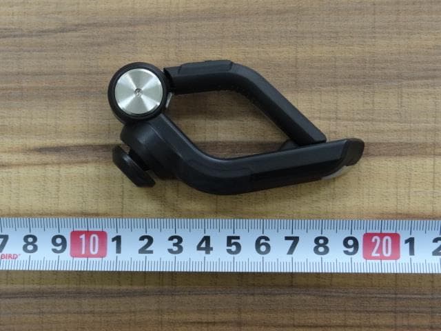
Click to zoom
Application Details
- Equipment Class
- DTS - Digital Transmission System
- Date of Grant
- Mar 15, 2015
- Application Purpose
- Original Equipment
- Date of Application
- Mar 15, 2015
- Equipment Note
- Handlebar Remote for Motorcycle Bluetooth Communication System
- Frequency Range
- 2402.00000000 - 2480.00000000
- Company
- Sena Technologies Co., Ltd.
- Country
- South Korea
Documents & Files
Document Text
Text extracted from the exhibit documents filed with the FCC. Open a document above to read the original.
Users Manual
| SC-HR-01 1 Handlebar Remote SENA www.sena.com User’s Guide | SC-HR-01 2 © 1998-2015 Sena Technologies, Inc. All rights reserved. Sena Technologies, Inc reserves the right to make any changes and improvements to its product without providing prior notice. Sena™ is a trademark of Sena Technologies, Inc. or its subsidiaries in the USA and other countries. 20S™, SMH10™, SMH5™, SMH5-FM™, SPH10™, SPH10H™, SPH10H-FM™, SMH10R™, SPH10S™, SPH10H™, SR10™, SM10™, EXPAND™, Bluetooth Pack for GoPro ® are trademarks of Sena Technologies, Inc. or its subsidiaries. These trademarks may not be used without the express permission of Sena. GoPro ® is a registered trademark of Woodman Labs of San Mateo, California. Sena Technologies, Inc. (“Sena”) is not affiliated with Woodman Labs. The Sena Bluetooth Pack for GoPro® is an after-market accessory specially designed and manufactured by Sena Technologies, Inc. for the GoPro® Hero3 allowing for Bluetooth capabilities. The Bluetooth® word mark and logos are owned by the Bluetooth SIG, Inc. and any use of such marks by Sena is under license. iPhone, iPod touch are registered trademarks of Apple Inc. Zumo™ is a trademark of Garmin Ltd. or its subsidiaries. TomTom™ is the trademark or registered trademark owned by TomTom International B.V. Other trademarks and tradenames are those of their respective owners. | SC-HR-01 3 1 INTRODUCTION Thank you for choosing the Sena Handlebar Remote, remote control for Sena motorcycle bluetooth headsets. With the Handlebar Remote, you can control your headset without getting your hand off of your handlebar. The Handlebar Remote is compliant with Bluetooth 4.0 Sena headsets. Check www.sena.com for more information. Hereby, SENA TECHNOLOGIES.Inc Declares that this SC-HR-01 is in compliance with the essential requirements and other relevant provisions of directive 1999/5/EC. 2 PACKAGE CONTENTS Handlebar Remote Unit | SC-HR-01 4 3 INSTALLING THE HANDLEBAR REMOTE 1. Stretch the opposite ends of the Handlebar Remote 2. Clip it on the motorcycle handlebar like the picture below. 4 GETTING STARTED | SC-HR-01 5 4.1 Charging You can charge the Handlebar Remote by connecting the supplied USB power & data cable into a computer’s USB port or USB wall charger. You can use any standard micro-USB cable to charge the Handlebar Remote. The LED turns red while the headset is charging and turns blue when it is fully charged. It takes about 2.5 hours to be fully charged. 4.2 Powering On and Off Press the Function Button to turn on the Handlebar Remote. Press the Phone Button and the Function Button simultaneously to turn off the device. 4.3 Buttons Matching - with Jog Dial Headsets Handlebar Remote Jog Dial Headset Tap Joystick Tap Jog Dial Push Joystick Up and Down Rotate Jog Dial Push Joystick Left and Right Rotate Jog Dial while Pressing Tap Phone Button Tap Phone Button Tap Function Button Tap Ambient Mode Button (20S Only) Tap Camera Button (10C Only) | SC-HR-01 6 5 PAIRING WITH YOUR HEADSET Before using the Handlebar Remote with any other Sena headsets for the first time, you will need to pair them together. The pairing operation is required only once for each Bluetooth device. The device remains paired with the headsets and automatically reconnects to them when they are within range. 1. Turn on the Handlebar Remote and press and hold the Function Button for 5 seconds. 2. Place the headset into intercom pairing mode. Please refer to the headset’s manual for details. 3. Tap the Jog Dial or the Center Button of the headset, and wait until the headset’s LED turns blue. Note: The Handlebar Remote is compliant only with Bluetooth 4.0 Sena Headsets. | SC-HR-01 7 6 REMOTE CONTROL FUNCTIONS 6.1 Mobile Phone Call Making and Answering Please have your headset Bluetooth paired to a phone before using the mobile phone functions with the Handlebar Remote. 1. When you have an incoming call, simply tap the Phone Button or the Joystick to answer the call. 2. To end a call, tap the Phone Button or press the Joystick for 2 seconds until you hear a beep, or wait for the called person to end the call. 3. To reject a call, press the Joystick for 2 seconds until you hear a beep while the phone is ringing. 4. To transfer a call between the mobile phone and the headset during the phone conversation, press the Phone Button for 2 seconds until you hear a beep. 5. Double tap the Phone Button to enter into speed dials. 6.2 Bluetooth Stereo Music Please have your headset Bluetooth paired to a media device before using the Bluetooth stereo music functions with the Handlebar Remote. 1. To play or pause music, press and hold the Joystick for 1 second until you hear a double beep. 2. To adjust volume, push the Joystick up or down. 3. To track forward or track back, push the Joystick left or right. 6.3 Intercom You can start an intercom conversation with one of any intercom friends by tapping the Joystick: single tap to intercom with the first intercom friend, double tap to intercom with the second intercom friend, and triple tap to intercom with the third intercom friend. To terminate an intercom conversation, single tap the Joystick. Any intercom connection with any intercom friend will be terminated by a single tap. A double or triple tap will do nothing in this case. 6.4 FM Radio To turn on the FM radio, press and hold the Phone Button for 2 seconds until you hear a mid-toned double beep sound. To turn off the FM radio, press and hold the Phone Button for 2 seconds. 1. You can listen to preset stations while listening to the FM radio. Tap the Phone Button once to go upward to your next saved preset station. 2. Push the Joystick right or left to seek station frequencies up or down. 3. Double tap the Phone Button to scan up the radio frequencies. Tap the Phone Button if you want to save the station. 4. Press and hold the Joystick for 2 seconds to enter into preset mode. Push the Joystick up or down to seek through the presets. Tap the Joystick if you want to save the preset.…
Text truncated - open the document above for the full version.
Block Diagram
Sena Technologies,Inc. 210 Yangjae-dong Seocho-gu, Seoul, South Korea, 137-130 Date: Mar. 05, 2015 SIEMIC 775 Montague Expressway Milpitas, CA 95035 Tel: 408-526-1188 Fax: 408-526-1088 Email: [email protected] Letter of Authorization We, the undersigned, hereby authorize Harvey Sung of DT&C Co., Ltd. to act on our behalf in all manners relating to application for equipment authorization for FCCID: S7A-SP19 including signing of all documents relating to these matters. Any and all acts carried out by Harvey Sung of DT&C Co., Ltd. on our behalf shall have the same affect as acts of our own. This authorization is valid until further written notice from Sena Technologies,Inc. “I, the undersigned, hereby certify that we are not subject to a denial of federal benefits, that includes FCC benefits, pursuant to Section 5301 of the Anti-Drug Abuse Act of 1988, 21 U.S.C. 853(a).” Sincerely, Seunghyun KIM Reasearch Engineer
Cover Letter(s)
SCS-F18: Project and Product Certification Representative Authorization Letter Page 1 of 2 Rev 5.0 775 Montague Expressway Milpitas, CA 95035 Tel: 408-526-1188 Fax: 408-526-1088 Email: [email protected] Project and Product Certification Representative Authorization Letter Reason for Amendment (current / obsolete) Revision History Approved Date From To Initial Release (obsolete) 1.0 1.0 Nov-14-2006 Revised wording (obsolete) 1.0 2.0 Sept–25-2007 Updated company template (obsolete) 2.0 3.0 Jan-31-2012 Updated letter information (obsolete) 3.0 4.0 May-23-2014 Added FCC ID field (current) 4.0 5.0 Sept 16 2014 SCS-F18: Project and Product Certification Representative Authorization Letter Page 2 of 2 Rev 5.0 Mar. 05, 2015 To: SIEMIC, INC. 775 Montague Expressway, Milpitas, CA 95035 USA Dear Sir/Madam, Re: Product Certification Representative Authorization Letter We, Sena Technologies,Inc.hereby authorize SIEMIC, Inc. to act as a Certification Body for certifying for the following project(s): (Handlebar Remote for Motorcycle Bluetooth Communication System, SC-HR-01) FCC ID:S7A-SP19 Sincerely, Client’s signature Client’s name / title Seunghyun KIM / Reasearch Engineer Contact information / address Sena Technologies,Inc. 210 Yangjae-dong Seocho-gu, Seoul, South Korea, 137-130
External Photos
FCCID: S7A-SP19 Copyright Ⓒ 2015, DT&C Co., Ltd. Page 1 / 2 View 1 FCCID: S7A-SP19 Copyright Ⓒ 2015, DT&C Co., Ltd. Page 2 / 2 View 2
ID Label/Location Info
FCC ID: S7A-SP19 IC: 8154A-SP19 Copyright Ⓒ 2015, DT&C Co., Ltd. FCC&IC ID SAMPLE LABEL & LOCATION LABELLING REQUIREMENTS PER §2.925 The Label shown shall be permanently affixed at a conspicuous location on the device and be readily visible to the user at the time of purchase - The FCC label shown is representative of the label that will appear on the radio when in production. Other information may also be included on this label. - The device is so small that it is not practicable to place the statement specified under 15.19 statement request, the information required by this paragraph shall be placed in a prominent location in the user's manual.
Internal Photos
FCCID: S7A-SP19 Copyright Ⓒ 2015, DT&C Co., Ltd. Page 1 / 3 View 1 FCCID: S7A-SP19 Copyright Ⓒ 2015, DT&C Co., Ltd. Page 2 / 3 View 2 FCCID: S7A-SP19 Copyright Ⓒ 2015, DT&C Co., Ltd. Page 3 / 3 View 3
RF Exposure Info
MHzmm = Typical Power: ± = [ / ] * [ √ ] 5 2480 - Min. test separation distance = mW 4.41 4.50 dBm - Min. transmitting frequency = dB 3.50 dBm 1.00 dBm Measured Output Power: S7A-SP19 300 248 5 - Max. power with turn-up tolerance = 3 Used Step 1) SAR test exclusion thresholds for 100MHz to 6GHz at te st separationn distances ≤ 50 mm = [(max. power of channel, including tune-up tolerance, mW)/(min. test separation distance, mm)] · [√f(GHz)] FCC ID : Standalone SAR test exclusion considerations March 9, 2015 = [ / ] [ √ ] = Thus SAR for this device is not required. [Threshold at 50 mm in step 1) + (test separation distance - 50 mm)·( f(MHz)/150)] mW [Threshold at 50 mm in step 1) + (test separation distance - 50 mm)·10] mW 5 Step 2-1) SAR test exclusion thresholds for 100MHz to 1500MHz at test separationn distances > 50 mm = N/A 0.94 ≤ 3, for 1g SAR Step 2-2) SAR test exclusion thresholds for 1500MHz to 6GHz at test separationn distances > 50 mm = N/A 3 . 00 2 . 48 Copyright Ⓒ 2014, DT&C Co., Ltd.
Test Report
FCCID: S7A-SP19 DTNC1502-00673 Report No.: DRTFCC1503-0035 TRF-RF-219(00)130701 Page2 / 35 Copyright ○ C 2015, DT&C Co., Ltd. Test Report Version Test Report No. Date Description DRTFCC1503-0035 Mar. 09, 2015 Initial issue FCCID: S7A-SP19 DTNC1502-00673 Report No.: DRTFCC1503-0035 TRF-RF-219(00)130701 Page3 / 35 Copyright ○ C 2015, DT&C Co., Ltd. Table of Contents 1. GENERAL INFORMATION ........................................................ 4 2. EUT DESCRIPTION ................................................................... 4 3. SUMMARY OF TESTS ............................................................... 5 4. TEST METHODOLOGY ............................................................. 6 4.1 EUT CONFIGURATION ..................................................................................... 6 4.2 EUT EXERCISE ................................................................................................. 6 4.3 GENERAL TEST PROCEDURES ...................................................................... 6 4.4 DESCRIPTION OF TEST MODES ..................................................................... 6 5. INSTRUMENT CALIBRATION ................................................... 7 6. FACILITIES AND ACCREDITATIONS ........................................ 7 6.1 FACILITIES ........................................................................................................ 7 6.2 EQUIPMENT ...................................................................................................... 7 7. ANTENNA REQUIREMENTS ..................................................... 7 8. TEST RESULT ........................................................................... 8 8.1 6dB Bandwidth Measurement .......................................................................... 8 8.2 Maximum Peak Conducted Output Power .................................................... 11 8.3 Maximum Power Spectral Density. ................................................................ 14 8.4 Out of Band Emissions at the Band Edge/ Conducted Spurious Emissions17 8.5 Radiated Measurement. .................................................................................. 26 8.5.1 Radiated Spurious Emissions. .................................................................. 26 8.6 POWERLINE CONDUCTED EMISSIONS ........................................................ 29 8.7 Occupied Bandwidth ...................................................................................... 32 9. LIST OF TEST EQUIPMENT .................................................... 33 APPENDIX I ................................................................................. 34 APPENDIX II ................................................................................ 35 FCCID: S7A-SP19 DTNC1502-00673 Report No.: DRTFCC1503-0035 TRF-RF-219(00)130701 Page4 / 35 Copyright ○ C 2015, DT&C Co., Ltd. 1. GENERAL INFORMATION Applicant : Sena Technologies,Inc. Address : 210 Yangjae-dong Seocho-gu, Seoul, South Korea 137-130 FCC ID : S7A-SP19 EUT : Handlebar Remote for Motorcycle Bluetooth Communication System Model : SC-HR-01 Additional Model(s) : N/A Data of Test : 2015-02-19 ~ 2015-02-27 Contact person : Seunghyun KIM 2. EUT DESCRIPTION Product Handlebar Remote for Motorcycle Bluetooth Communication System Model Name SC-HR-01 Power Supply DC 3.7 V Battery type Standard Battery: Lithium Ion Battery Frequency Range 2402 ~ 2480MHz (40 channels) Max. RF Output Power 4.41 dBm Modulation Type GFSK Antenna Specification Antenna Type: Internal Antenna Gain: 0.5 dBi(PK) FCCID: S7A-SP19 DTNC1502-00673 Report No.: DRTFCC1503-0035 TRF-RF-219(00)130701 Page5 / 35 Copyright ○ C 2015, DT&C Co., Ltd. 3. SUMMARY OF TESTS FCC Part Section(s) RSS Section(s) Parameter Limit Test Condition Status Note 1 I. Transmitter Mode (TX) 15.247(a) RSS-210 [A8.2] 6 dB Bandwidth > 500 kHz Conducted C 15.247(b) RSS-210 [A8.4] Transmitter Output Power < 1Watt C 15.247(d) RSS-210 [A8.5] Out of Band Emissions / Band Edge 20dBc in any 100kHz BW C 15.247(e) RSS-210 [A8.2] Transmitter Power Spectral Density < 8dBm / 3kHz C - RSS Gen [6.6] Occupied Bandwidth (99%) RSS-Gen [6.6] NA 15.205 15.209 RSS-210 [A8.5] General Field Strength Limits (Restricted Bands and Radiated Emission Limits) < FCC 15.209 limits Radiated C Note2 15.207 RSS-Gen [8.8] AC Conducted Emissions < FCC 15.207 limits AC Line Conducted C 15.203 - Antenna Requirements FCC 15.203 - C Note 1: C=Comply NC=Not Comply NT=Not Tested NA=Not Applicable Note 2: This test item was performed in each axis and the worst case data was reported. FCCID: S7A-SP19 DTNC1502-00673 Report No.: DRTFCC1503-0035 TRF-RF-219(00)130701 Page6 / 35 Copyright ○ C 2015, DT&C Co., Ltd. 4. TEST METHODOLOGY Generally the tests were performed according to the KDB558074 v03r02. And ANSI C63.10-2009 was used to reference appropriate EUT setup and maximizing procedures of radiated spurious emission and AC line conducted emission testing. 4.1 EUT CONFIGURATION The EUT configuration for testing is installed on RF field strength measurement to meet the Commissions requirement and operating in a manner that intends to maximize its emission characteristics in a continuous normal application. 4.2 EUT EXERCISE The EUT was operated in the test mode to fix the TX frequency that was for the purpose of the measurements. According to its specifications, the EUT must comply with the requirements of the Section 15.207, 15.209 and 15.247 under the FCC Rules Part 15 Subpart C. 4.3 GENERAL TEST PROCEDURES Conducted Emissions According to the requirements in Section 6.2 of ANSI C63.10, the EUT is placed on the non-conductive table, which is 0.8 m above ground plane and the conducted emissions from the EUT are measured in the frequency range between 0.15 MHz and 30MHz using CISPR Quasi-peak and Average detector. Radiated Emissions The EUT is placed on a non-conductive table, which is 0.8 m above ground plane. The turntable shall rotate 360 degrees to determi…
Text truncated - open the document above for the full version.
Test Setup Photos
FCCID: S7A-SP19 Copyright Ⓒ 2015, DT&C Co., Ltd. Test Setup photographs EUT Position: X-axis EUT Position: Y-axis EUT Position: Z-axis FCCID: S7A-SP19 Copyright Ⓒ 2015, DT&C Co., Ltd. Test Setup Photo of Radiated Measurement (0.009 ~ 30MHz) FCCID: S7A-SP19 Copyright Ⓒ 2015, DT&C Co., Ltd. Test Setup Photo of Radiated Measurement (below 1000MHz) FCCID: S7A-SP19 Copyright Ⓒ 2015, DT&C Co., Ltd. Test Setup Photo of Radiated Measurement (Above 1GHz) FCCID: S7A-SP19 Copyright Ⓒ 2015, DT&C Co., Ltd. Test Setup Photo for AC Conducted Emissions
Contact Information
Applicant
Seunghyun KIM(Research Engineer)
Test Firm
DT&C Co., Ltd.WonJung Lee
Technical Specifications
| # | Rule Parts | Frequency Range | Power Output |
|---|---|---|---|
| 1 | 15C | 2.40 GHz - 2.48 GHz | 2.76 mW |
Other Applications from Sena Technologies Co., Ltd.
S7A-SP196
Jun 15, 2026Wireless Communication Systems
Equipment Class
NII - Unlicensed National Information Infrastructure TXS7A-SP198
May 07, 2026Wireless Communication Systems
Equipment Class
DTS - Digital Transmission SystemS7A-SP197
Apr 06, 2026Wireless Communication Systems
Equipment Class
DTS - Digital Transmission SystemS7A-SP195
Apr 06, 2026Wireless Communication Systems
Equipment Class
DTS - Digital Transmission SystemS7A-SP158
Mar 13, 2026Wireless Communication Systems
Equipment Class
DSS - Part 15 Spread Spectrum Transmitter