S7A-SP20Motorcycle Bluetooth Communication System
Sena Technologies Co., Ltd.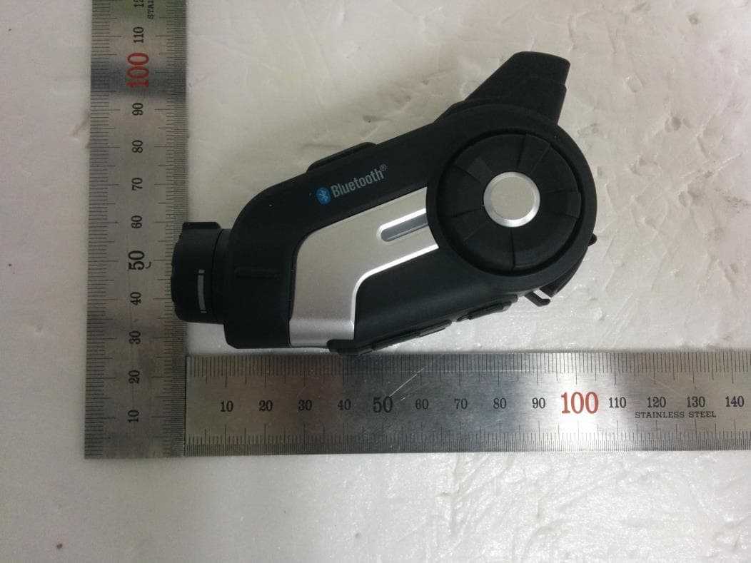
Click to zoom
Application Details
- Equipment Class
- DTS - Digital Transmission System
- Date of Grant
- Apr 14, 2015
- Application Purpose
- Original Equipment
- Date of Application
- Apr 14, 2015
- Equipment Note
- Motorcycle Bluetooth Communication System
- Frequency Range
- 2402.00000000 - 2480.00000000
- Company
- Sena Technologies Co., Ltd.
- Country
- South Korea
Documents & Files
Document Text
Text extracted from the exhibit documents filed with the FCC. Open a document above to read the original.
Users Manual
10C Motorcycle Bluetooth ® Camera & Communication System SENA www.sena.com User’s Guide © 1998-2015 Sena Technologies, Inc. All rights reserved. Sena Technologies, Inc reserves the right to make any changes and improvements to its product without providing prior notice. Sena™ is a trademark of Sena Technologies, Inc. or its subsidiaries in the USA and other countries. 20S™, PRISM™, Snowtalk™, 3S™, SMH10™, SMH5™, SMH5-FM™, SPH10™, SPH10H-FM™, SMH10R™, SPH10S™, SPH10H™, SR10™, SR10i™, SMH10™, EXPAND™, Bluetooth Pack for GoPro® are trademarks of Sena Technologies, Inc. or its subsidiaries. These trademarks may not be used without the express permission of Sena. GoPro® is a registered tradmeark of Woodman Labs of San Mateo, California. Sena Technologies Inc. (“Sena”) is not affiliated with Woodman Labs. The Sena Bluetooth Pack for GoPro® is an after-market accessory specially designed and manufactured by Sena Technologies, Inc. for the GoPro® Hero3 allowing for Bluetooth capabilities. The Bluetooth® word mark and logos are owned by the Bluetooth SIG, Inc. and any use of such marks by Sena is under license. iPhone, iPod touch are registered trademarks of Apple Inc. Zumo™ is a trademark of Garmin Ltd. or its subsidiaries. TomTom™ is the trademark or registered trademark owned by TomTom International B.V. Other trademarks and tradenames are those of their respective owners. CONTENTS 1 INTRODUCTION 2 PACKAGE CONTENTS 3 INSTALLING THE 10C ON YOUR HELMET 4 GETTING STARTED 4.1 Button Operation 4.2 Powering On and Off 4.3 Charging 4.4 Checking the Battery Level 4.4.1 LED Indicator 4.4.2 Voice Prompt Indicator 4.5 Volume Adjustment 4.6 Sena Softwares 4.6.1 Sena Device Manager 4.6.2 Sena Smartphone App 5 CAMERA OPERATION 5.1 Camera On or Off 5.2 Camera Modes 5.3 Video Recording 5.4 Photo Shooting 5.5 Video Tagging 5.6 Playback 6 PAIRING THE 10C WITH BLUETOOTH DEVICES 6.1 Mobile Phone Pairing - Mobile Phone, Bluetooth Stereo Device 6.2 Second Mobile Phone Pairing - Second Mobile Phone, GPS, and SR10 6.3 Intercom Pairing 6.3.1 Pairing with Other 10C Headsets for Intercom Conversation 6.3.2 Pairing with Other Sena Headset Models for Intercom Conversation 6.4 Advanced Selective Pairing: A2DP Stereo or Handsfree 6.4.1 A2DP Stereo Music Only 6.4.2 HFP for Phone Call Only 7 MOBILE PHONE, GPS, SR10 7.1 Mobile Phone Call Making and Answering 7.2 Speed Dialing 7.3 GPS Navigation 7.4 Sena SR10, Two-Way Radio Adapter 8 STEREO MUSIC 8.1 Bluetooth Stereo Music 8.2 Music Sharing 9 INTERCOM 9.1 Two-way Intercom 9.1.1 Starting Two-way Intercom 9.1.2 Ending Two-way Intercom 9.2 Three-way Intercom 9.2.1 Starting Three-way Intercom 9.2.2 Ending Three-way Intercom 9.3 Four-way Intercom 9.3.1 Starting Four-way Intercom 9.3.2 Ending Four-way Intercom 10 THREE-WAY CONFERENCE PHONE CALL WITH INTERCOM PARTICIPANT 11 UNIVERSAL INTERCOM 11.1 Universal Intercom Pairing 11.2 Two-way Universal Intercom 11.3 Three-way Universal Intercom 11.4 Four-way Universal Intercom 11.4.1 Four-way Universal Intercom Case 1 11.4.2 Four-way Universal Intercom Case 2 12 FM RADIO 12.1 FM Radio On/Off 12.2 Preset Stations 12.3 Seek and Save 12.4 Scan and Save 12.5 Temporary Preset 12.6 Region Selection 13 FUNCTION PRIORITY 14 CONFIGURATION SETTING 14.1 Headset Configuration Setting 14.1.1 Assigning Speed Dial 14.1.2 Enabling/Disabling Voice Activated Phone Answering 14.1.3 Enabling/Disabling Voice Activated Intercom 14.1.4 Enabling/Disabling Voice Prompts 14.1.5 Delete All Bluetooth Pairing Information 14.1.6 Exit Voice Configuration Menu 14.2 Camera Configuration Setting 14.2.1 Photo Mode 14.2.2 Video Mode 14.2.3 Video Resolution 14.2.4 Timelapse Interval Setting 14.2.5 Date Caption On/Off 14.2.6 Microphone On/Off 14.2.7 Auto Camera Sleep 14.2.8 SD Card Format 15 FIRMWARE UPGRADE 16 TROUBLESHOOTING 16.1 Intercom Failure 16.2 Intercom Reconnection 16.3 Fault Reset 16.4 Factory Reset 17 OPERATION QUICK REFERENCE CERTIFICATION AND SAFETY APPROVALS FCC Compliance Statement FCC RF Exposure Statement FCC Caution CE Declaration of Conformity Industry Canada Statement Bluetooth License WEEE (Waste Electrical and Electronic Equipment) SAFETY INFORMATION Product Storage and Management Product Use Battery PRODUCT WARRANTY AND DISCLAIMER Limited Warranty Warranty Exclusions Reasons for Limited Liabilities Limitation of Liability Liabilities Disclaimer Warranty Service Free-of-charge Service Charged Service Return for Full Refund 1 INTRODUCTION Thank you for choosing the Sena 10C, Motorcycle Bluetooth Camera & Communication System. With the 10C, you can record videos, take photos, call handsfree on your Bluetooth mobile phone, listen to stereo music or voice instructions of GPS navigations wirelessly, and have intercom conversations in full duplex with a passenger or other motorcycle riders. The 10C is compliant with the Bluetooth 4.1 supporting the following profiles: Headset Profile, Hands-Free Profile (HFP), Advanced Audio Distribution Profile (A2DP), and Audio Video Remote Control Profile (AVRCP). Please check with the manufacturers of other device to determine their compatibility with this headset. Please read this user’s guide carefully before using the headset. Also check www.sena.com for the latest version of the user’s guide and additional information related to Sena Bluetooth products. The 10C features: ● Bluetooth 4.1 ● Unibody design for Bluetooth headset and video camera ● 1080p Full HD video with 3.5MP still shot image capture ● Video mode: 1080p:30fps, 720p:30/60fps ● Versatile photo mode: shot, burst and timelapse shot functions ● Pitch angle adjustment ● Lens rotation up to 30 degrees ● Support Micro SD 32GB memory card (not included) ● Bluetooth intercom up to 900 meters (980 yards) ● Four-way intercom ● Voice prompts ● Voice recording with background music overlay ● Smartphone App for iPhone and Android ● Advanced Noise Control™ ● Universal Intercom™ ● Music sharing ● Built-in FM radio tuner with a station scan and save function ● Easy operati…
Text truncated - open the document above for the full version.
Cover Letter(s)
Sena Technologies,Inc. 210 Yangjae-dong Seocho-gu, Seoul, South Korea, 137-130 Date: April. 01, 2015 Timco Engineering, Inc. 849 N.W. State Road 45 P.O. Box 370 Newberry, Florida 32669 USA Letter of Authorization We, the undersigned, hereby authorize Harvey Sung of DT&C Co., Ltd. to act on our behalf in all manners relating to application for equipment authorization for FCC ID: S7A-SP20 including signing of all documents relating to these matters. Any and all acts carried out by Harvey Sung of DT&C Co., Ltd. on our behalf shall have the same affect as acts of our own. This authorization is valid until further written notice from Sena Technologies,Inc. “I, the undersigned, hereby certify that we are not subject to a denial of federal benefits, that includes FCC benefits, pursuant to Section 5301 of the Anti-Drug Abuse Act of 1988, 21 U.S.C. 853(a).” Sincerely, Seunghyun KIM Reasearch Engineer
Cover Letter(s)
Sena Technologies,Inc. 210 Yangjae-dong Seocho-gu, Seoul, South Korea, 137-130 Date: April. 01, 2015 Timco Engineering, Inc. 849 N.W. State Road 45 P.O. Box 370 Newberry, Florida 32669 USA RE: Request of Confidentiality for FCCID: S7A-SP20 To Whom It may Concern: Pursuant to Sections 0.457 and 0.459 of the Commission`s Rules(CFR 47), and Section 552 (b) (4) of the Freedom of Information Act, Sena Technologies,Inc. hereby requests confidentiality and treatment of certain information accompanying this application. The materials contain trade secrets and proprietary information not customarily released to the public. The public disclosure of these matters might be harmful to the Applicant and provide unjustified benefits to its competitors. We are also hereby request Short-Term Confidentiality for 180 days after the grant as outlined in Public Notice DA 04-1705. This provision will give Sena Technologies,Inc. temporary confidentiality of commercially sensitive information prior to product release. The requested permanent and Short-Term Confidential exhibits are listed as follows: PERMANENT & SHORT-TERM CONFIDENTIAL LIST Exhibit Description PERMANENT 1 Block Diagram 2 Schematics 3 Operational Description 4 Part Lists SHORT-TERM 5 External Photos 6 Internal Photos 7 Test-Setup Photos 8 User Manual The Applicant understands that pursuant to Rule 0.457, disclosure of this application and all accompanying documentations, where applicable, will not be public before the date of the Grant for this application. Sincerely, Seunghyun KIM Reasearch Engineer
Cover Letter(s)
Sena Technologies,Inc. 210 Yangjae-dong Seocho-gu Seoul 137-130 Korea Date: April 7, 2015 Timco Engineering, Inc. 849 N.W. State Road 45 P.O. Box 370 Newberry, Florida 32669 USA DECLARATION FOR ADDITIONAL FREQUENCY HOPPING REQUIREMENTS To whom it may concern: We hereby declare that the device of S7A-SP20 meet following FCC requirements of the Section 15.247(a)(1) : 1. The hopping sequence is pseudorandom. 2. All channels are used equally on average. 3. The receiver input bandwidth approximately equal the transmit bandwidth. 4. The receiver hop in sequence with the transmit signal. Sincerely, Seunghyun Kim Reasearch Engineer
External Photos
FCCID: S7A-SP20 IC:8154A-SP20 Copyright Ⓒ 2015, DT&C Co., Ltd. Page 1 / 3 View 1 FCCID: S7A-SP20 IC:8154A-SP20 Copyright Ⓒ 2015, DT&C Co., Ltd. Page 2 / 3 View 2 FCCID: S7A-SP20 IC:8154A-SP20 Copyright Ⓒ 2015, DT&C Co., Ltd. Page 3 / 3 View 3
ID Label/Location Info
FCC ID: S7A-SP20 IC: 8154A-SP20 Copyright Ⓒ 2015, DT&C Co., Ltd. SAMPLE LABEL & LOCATION LABELLING REQUIREMENTS The Label shown shall be permanently affixed at a conspicuous location on the device and be readily visible to the user at the time of purchase - The FCC label shown is representative of the label that will appear on the radio when in production. Other information may also be included on this label. - The device is so small that it is not practicable to place the statement specified under 15.19 statement requests, The information required by this paragraph shall be placed in a prominent location in the user manual.
Internal Photos
FCCID: S7A-SP20 IC:8154A-SP20 Copyright Ⓒ 2015, DT&C Co., Ltd. Page 1 / 8 View 1 FCCID: S7A-SP20 IC:8154A-SP20 Copyright Ⓒ 2015, DT&C Co., Ltd. Page 2 / 8 View 2 FCCID: S7A-SP20 IC:8154A-SP20 Copyright Ⓒ 2015, DT&C Co., Ltd. Page 3 / 8 View 3 FCCID: S7A-SP20 IC:8154A-SP20 Copyright Ⓒ 2015, DT&C Co., Ltd. Page 4 / 8 View 4 FCCID: S7A-SP20 IC:8154A-SP20 Copyright Ⓒ 2015, DT&C Co., Ltd. Page 5 / 8 View 5 FCCID: S7A-SP20 IC:8154A-SP20 Copyright Ⓒ 2015, DT&C Co., Ltd. Page 6 / 8 View 6 FCCID: S7A-SP20 IC:8154A-SP20 Copyright Ⓒ 2015, DT&C Co., Ltd. Page 7 / 8 View 7 FCCID: S7A-SP20 IC:8154A-SP20 Copyright Ⓒ 2015, DT&C Co., Ltd. Page 8 / 8 View 6 <Antenna>
Operational Description
Preliminary SPECIFICATION Chip Antenna Model No. : SENA_009 WRITTENCHECKEDAPPROVED Seunghyun KimSeunghyun Kim July 22, 2009 Notes The contents of this data sheet are subject to change without notice.Please confirm the specifications and delivery conditions when placing your order. -2 -CHIP ANTENNA 1. SPECIFICATIONS 1.1. Electrical Specifications ITEMSPEC.Unit Frequency2400-2485MHz Bandwidth @ VSWR 2.5:1100MHz Gain Max.1dBi PolarizationLinear Azimuth Beam PatternOmni-directional Impedance50 Ω ※These values are measured on the matched reference test board. 1.2. Mechanical Specifications ElectrodeSilver Dimensions (L x W x H)9.0 x 3.0 x 1.2mm Operating Temperature-35 ~ +85 °C 1.3. Appearance and Dimensions L9.0 W3.0 H1.2 -3 -CHIP ANTENNA 2. MEASUREMENT 2.1. Electrical Characteristic S 11 (Return Loss) B. (Smith chart) -4 -CHIP ANTENNA 3. Radiation Data FrequencyEfficiency Average GainMax Gain Max PositionDirectivity VerHorTotalVerHorTotal 2400 MHz37.4 %-6.6 dBi-8.0 dBi-4.3 dBi-1.1 dBi-0.9 dBi0.1 dBiTheta135/Pie2554.34 dB 2442 MHz43.0 %-6.0 dBi-7.5 dBi-3.7 dBi-0.3 dBi-0.1 dBi0.5 dBiTheta15/Pie2404.60 dB 2485 MHz37.2 %-6.6 dBi-8.1 dBi-4.3 dBi-0.1 dBi-0.2 dBi0.2 dBiTheta135/Pie2554.91 dB -5 -CHIP ANTENNA 4. RELIABILITY TEST NoItemTest conditionTest Requirements 1 Adhesion strength . Applied force on SMD chip till detached point from PCB 1. No mechanical damage by forces applied on the right 2. Strength (F) > 5 kgf 2 Thermal Shock (Temperature Cycle) 1. 1 cycle / step 1 : -40±3°C, 30 min step 2 : +85±3°C, 30 min 2. Number of cycle : 10 3. Measure after left for 48 hrs min. at room temperature 1. No visual damage 2. VSWR satisfy 3 High Temperature Resistance 1. Temperature: +85±5°C 2. Time : 96 hrs 3. Measure VSWR C after left for 24 hrs min. at room temperature 1. No visual damage 2. VSWR satisfy 4 Low Temperature Resistance 1. Temperature: -40±5°C 2. Time : 96 hrs 3. Measure VSWR C after left for 48 hrs min. at room temperature 1. No visual damage 2. VSWR satisfy 5 Humidity (Steady Condition) 1. Humidity : 85 % RH 1. Temperature: +85±3°C 2. Time : 96 hrs 3. Measure VSWR C after left for 48 hrs min. at room temperature 1. No visual damage 2. VSWR satisfy 6 ESD 1. ESD Level : 8KV 2. Mode : Contact discharge 3. Number of cycle : 100 ※ Used Ref test PCB. 1. No visual damage 2. VSWR satisfy F PCB -6 -CHIP ANTENNA 5. SOLDERING RECOMMENDATIOS 5.1. Reflow Soldering Profile A. Non Pb free 25 150 230 200 60 sec 20 ~ 40 sec T e m p e r a t e ( °C ) Time (sec) Cooling zone (slowly) 100 100 ~ 120sec B. Pb free 240°C±5°C(Peaktemp.) 230°C
RF Exposure Info
MHzmm = Typical Power: ± = [ / ] * [ √ ] 5 2480 - Min. test separation distance = mW 11.95 12.00 dBm - Min. transmitting frequency = dB 8.50 dBm 3.50 dBm Measured Output Power: S7A-SP20 16 00 248 5 - Max. power with turn-up tolerance = 16 Used Step 1) SAR test exclusion thresholds for 100MHz to 6GHz at te st separationn distances ≤ 50 mm = [(max. power of channel, including tune-up tolerance, mW)/(min. test separation distance, mm)] · [√f(GHz)] FCC ID : Standalone SAR test exclusion considerations April 1, 2015 = [ / ] [ √ ] = Thus SAR for this device is not required. [Threshold at 50 mm in step 1) + (test separation distance - 50 mm)·( f(MHz)/150)] mW [Threshold at 50 mm in step 1) + (test separation distance - 50 mm)·10] mW 5 Step 2-1) SAR test exclusion thresholds for 100MHz to 1500MHz at test separationn distances > 50 mm = N/A 5.04 ≤ 7.5, for 10g extrmity SAR Step 2-2) SAR test exclusion thresholds for 1500MHz to 6GHz at test separationn distances > 50 mm = N/A 16 . 00 2 . 48 Copyright Ⓒ 2015, DT&C Co., Ltd.
Test Report
FCCID: S7A-SP20 DTNC1503-00992 Report No.: DRTFCC1504-0073 TRF-RF-219(00)130701 Page2 / 33 Copyright ○ C 2015, DT&C Co., Ltd. Test Report Version Test Report No. Date Description DRTFCC1504-0073 Apr. 01, 2015 Initial issue FCCID: S7A-SP20 DTNC1503-00992 Report No.: DRTFCC1504-0073 TRF-RF-219(00)130701 Page3 / 33 Copyright ○ C 2015, DT&C Co., Ltd. Table of Contents 1. GENERAL INFORMATION ........................................................ 4 2. EUT DESCRIPTION ................................................................... 4 3. SUMMARY OF TESTS ............................................................... 5 4. TEST METHODOLOGY ............................................................. 6 4.1 EUT CONFIGURATION ..................................................................................... 6 4.2 EUT EXERCISE ................................................................................................. 6 4.3 GENERAL TEST PROCEDURES ...................................................................... 6 4.4 DESCRIPTION OF TEST MODES ..................................................................... 6 5. INSTRUMENT CALIBRATION ................................................... 7 6. FACILITIES AND ACCREDITATIONS ........................................ 7 6.1 FACILITIES ........................................................................................................ 7 6.2 EQUIPMENT ...................................................................................................... 7 7. ANTENNA REQUIREMENTS ..................................................... 7 8. TEST RESULT ........................................................................... 8 8.1 6dB Bandwidth Measurement .......................................................................... 8 8.2 Maximum Peak Conducted Output Power .................................................... 11 8.3 Maximum Power Spectral Density. ................................................................ 14 8.4 Out of Band Emissions at the Band Edge/ Conducted Spurious Emissions17 8.5 Radiated Measurement. .................................................................................. 26 8.5.1 Radiated Spurious Emissions. .................................................................. 26 8.6 POWERLINE CONDUCTED EMISSIONS ........................................................ 29 8.7 Occupied Bandwidth ...................................................................................... 30 9. LIST OF TEST EQUIPMENT .................................................... 31 APPENDIX I ................................................................................. 32 APPENDIX II ................................................................................ 33 FCCID: S7A-SP20 DTNC1503-00992 Report No.: DRTFCC1504-0073 TRF-RF-219(00)130701 Page4 / 33 Copyright ○ C 2015, DT&C Co., Ltd. 1. GENERAL INFORMATION Applicant : Sena Technologies,Inc. Address : 210 Yangjae-dong Seocho-gu, Seoul, South Korea 137-130 FCC ID : S7A-SP20 EUT : Motorcycle Bluetooth Communication System Model : 10C Additional Model(s) : N/A Data of Test : 2015-03-17 ~ 2015-03-27 Contact person : Seunghyun KIM 2. EUT DESCRIPTION Product Motorcycle Bluetooth Communication System Model Name 10C Power Supply DC 3.7 V Battery type Standard Battery: Lithium Ion Battery Frequency Range 2402 ~ 2480MHz (40 channels) Max. RF Output Power 7.83 dBm Modulation Type GFSK Antenna Specification Antenna Type: Internal Antenna Gain: 0.5 dBi(PK) FCCID: S7A-SP20 DTNC1503-00992 Report No.: DRTFCC1504-0073 TRF-RF-219(00)130701 Page5 / 33 Copyright ○ C 2015, DT&C Co., Ltd. 3. SUMMARY OF TESTS FCC Part Section(s) RSS Section(s) Parameter Limit Test Condition Status Note 1 I. Transmitter Mode (TX) 15.247(a) RSS-210 [A8.2] 6 dB Bandwidth > 500 kHz Conducted C 15.247(b) RSS-210 [A8.4] Transmitter Output Power < 1Watt C 15.247(d) RSS-210 [A8.5] Out of Band Emissions / Band Edge 20dBc in any 100kHz BW C 15.247(e) RSS-210 [A8.2] Transmitter Power Spectral Density < 8dBm / 3kHz C - RSS Gen [6.6] Occupied Bandwidth (99%) RSS-Gen [6.6] NA 15.205 15.209 RSS-210 [A8.5] General Field Strength Limits (Restricted Bands and Radiated Emission Limits) < FCC 15.209 limits Radiated C Note3 15.207 RSS-Gen [8.8] AC Conducted Emissions < FCC 15.207 limits AC Line Conducted NA Note 2 15.203 - Antenna Requirements FCC 15.203 - C Note 1: C=Comply NC=Not Comply NT=Not Tested NA=Not Applicable Note 2: The power of this device is only DC(Internal Battery) and Bluetooth LE function is disabled in charging status. Note 3: This test item was performed in each axis and the worst case data was reported. FCCID: S7A-SP20 DTNC1503-00992 Report No.: DRTFCC1504-0073 TRF-RF-219(00)130701 Page6 / 33 Copyright ○ C 2015, DT&C Co., Ltd. 4. TEST METHODOLOGY Generally the tests were performed according to the KDB558074 v03r02. And ANSI C63.10-2009 was used to reference appropriate EUT setup and maximizing procedures of radiated spurious emission and AC line conducted emission testing. 4.1 EUT CONFIGURATION The EUT configuration for testing is installed on RF field strength measurement to meet the Commissions requirement and operating in a manner that intends to maximize its emission characteristics in a continuous normal application. 4.2 EUT EXERCISE The EUT was operated in the test mode to fix the TX frequency that was for the purpose of the measurements. According to its specifications, the EUT must comply with the requirements of the Section 15.207, 15.209 and 15.247 under the FCC Rules Part 15 Subpart C. 4.3 GENERAL TEST PROCEDURES Conducted Emissions According to the requirements in Section 6.2 of ANSI C63.10, the EUT is placed on the non-conductive table, which is 0.8 m above ground plane and the conducted emissions from the EUT are measured in the frequency range between 0.15 MHz and 30MHz using CISPR Quasi-peak and Average detector. Radiated Emissions The EUT is placed on a non-conductive table, which is…
Text truncated - open the document above for the full version.
Test Setup Photos
FCCID: S7A-SP20 Copyright Ⓒ 2015, DT&C Co., Ltd. Test Setup photographs EUT Position: X-axis EUT Position: Y-axis EUT Position: Z-axis FCCID: S7A-SP20 Copyright Ⓒ 2015, DT&C Co., Ltd. Test Setup Photo of Radiated Measurement (0.009 ~ 30MHz) FCCID: S7A-SP20 Copyright Ⓒ 2015, DT&C Co., Ltd. Test Setup Photo of Radiated Measurement (below 1000MHz) FCCID: S7A-SP20 Copyright Ⓒ 2015, DT&C Co., Ltd. Test Setup Photo of Radiated Measurement (Above 1GHz)
Contact Information
Applicant
Seunghyun KIM(Research Engineer)
Test Firm
DT&C Co.,Changho Lee
Technical Specifications
| # | Rule Parts | Frequency Range | Power Output |
|---|---|---|---|
| 1 | 15C | 2.40 GHz - 2.48 GHz | 6.07 mW |
Other Applications from Sena Technologies Co., Ltd.
S7A-SP196
Jun 15, 2026Wireless Communication Systems
Equipment Class
NII - Unlicensed National Information Infrastructure TXS7A-SP198
May 07, 2026Wireless Communication Systems
Equipment Class
DTS - Digital Transmission SystemS7A-SP197
Apr 06, 2026Wireless Communication Systems
Equipment Class
DTS - Digital Transmission SystemS7A-SP195
Apr 06, 2026Wireless Communication Systems
Equipment Class
DTS - Digital Transmission SystemS7A-SP158
Mar 13, 2026Wireless Communication Systems
Equipment Class
DSS - Part 15 Spread Spectrum Transmitter