S7A-SP843S PLUS
Sena Technologies Co., Ltd.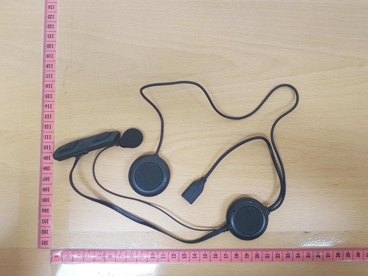
Click to zoom
Application Details
- Equipment Class
- DTS - Digital Transmission System
- Date of Grant
- Aug 19, 2020
- Application Purpose
- Original Equipment
- Date of Application
- Aug 19, 2020
- Equipment Note
- 3S PLUS
- Frequency Range
- 2402.00000000 - 2480.00000000
- Company
- Sena Technologies Co., Ltd.
- Country
- South Korea
Documents & Files
Document Text
Text extracted from the exhibit documents filed with the FCC. Open a document above to read the original.
Users Manual
| 3S PLUS 1 3S PLUS Motorcycle Bluetooth Headset & Intercom SENA www.senabluetooth.com User’s Guide | 3S PLUS 2 © 1998-2013 Sena Technologies, Inc. All rights reserved. Sena Technologies, Inc reserves the right to make any changes and improvements to its product without providing prior notice. Sena™ is a trademark of Sena Technologies, Inc. or its subsidiaries in the USA and other countries. The Bluetooth® word mark and logos are owned by the Bluetooth SIG, Inc. and any use of such marks by Sena is under license. Other trademarks and tradenames are those of their respective owners. | 3S PLUS 3 CONTENTS 1. INTRODUCTION 2. PACKAGE CONTENTS 3. INSTALLING THE 3S PLUS ON YOUR HELMET 4. POWERING ON/OFF AND CHARGING 4.1 Powering On 4.2 Powering Off 4.3 Charging 4.4 Low Battery Warning 5. CHECKING THE BATTERY LEVEL 5.1 LED Indicator 5.2 Voice Prompt Indicator 6. PAIRING THE 3S PLUS WITH BLUETOOTH DEVICES 6.1 Mobile Phone Pairing 6.2 Multipoint Mobile Phones Pairing 6.3 Bluetooth Stereo Device Pairing 6.4 Bluetooth GPS Navigation Pairing 7. PAIRING WITH OTHER SMH3 HEADSETS FOR INTERCOM CONVERSATION 8. 3S PLUS CONFIGURATION SETTING 8.1 Enabling/Disabling Voice Activated Phone Answering 8.2 Enabling/Disabling Voice Prompts 8.3 Delete All Bluetooth Pairing Information 8.4 Reset to Factory Default Setting 8.5 Exit Voice Configuration Menu 9. USING THE 3S PLUS 9.1 Volume Adjustment 9.2 Mobile Phone Call Making and Answering 9.3 Intercom Conversation 9.4 Intercom and Mobile Phone Call 9.5 Intercom Failure 9.6 Intercom Reconnection 9.7 Stereo Music 9.8 Function Priority 9.9 Fault Reset 10. FIRMWARE UPGRADE | 3S PLUS 4 1. INTRODUCTION Thank you for choosing the Sena 3S PLUS, Motorcycle Bluetooth Headset and Intercom. With the 3S PLUS, you can call handsfree on your Bluetooth mobile phone, listen to stereo music or voice instructions of GPS navigation by Bluetooth wirelessly, and have intercom conversations in full duplex with a passenger or other riders. The 3S PLUS is compliant with the Bluetooth Specification 4.1 supporting the following profiles: Headset Profile, Hands- Free Profile (HFP), Advanced Audio Distribution Profile (A2DP), and Audio Video Remote Control Profile (AVRCP). Please check with the manufacturers of other devices to determine their compatibility with this headset. Please read this user’s guide carefully before using the headset. Also check www.SenaBluetooth.com for the latest version of the user’s guide and additional information related to Sena Bluetooth products. The 3S PLUS features: ● Bluetooth handsfree for Bluetooth mobile phones ● Bluetooth stereo headset for Bluetooth stereo devices such as MP3 players ● Bluetooth stereo headset for Bluetooth GPS navigations ● Bluetooth intercom ● Easy operation by two-button ● Installation friendly unibody design ● Firmware upgradeable Key Specifications: ● Bluetooth 4.1 ● Supporting profiles: Headset Profile, Hands-Free Profile (HFP), Advanced Audio Distribution Profile (A2DP), Audio Video Remote Control Profile (AVRCP) ------------- *In open terrain | 3S PLUS 5 2. PACKAGE CONTENTS 3S PLUS Headset Unit Microphone Sponges USB C Power Cable Velcro Pads for Speakers | 3S PLUS 6 3. INSTALLING THE 3S PLUS ON YOUR HELMET 1. [picture 3-1] 2. [picture 3-2] 3. [picture 3-3] Remove the left and right side cheekpads from the helmet. Place the speaker-microphone unit along with the velcro pad to the left inside surface of the external shell, centered to your ear. The boom microphone should be positioned to face properly towards your mouth. Please make sure that the microphone is located close to your mouth when you wear the helmet. 4. [picture 3-4] 5. [picture 3-5] 6. [picture 3-6] Place the speaker unit along with the velcro pad to the right inside surface of the external shell, centered to your year in the ear pockets of the helmet Lift up the helmet top padding from the back of the helmet and rout the speaker wires beneath the padding. Replace the cheeckpads in the helmet making sure the speaker wiring is hidden beneath the padding | 3S PLUS 7 4. POWERING ON/OFF AND CHARGING 4.1 Powering On Press the (+) Button and the (-) Button at the same time for 1 second to power on. The blue LED turns on and you will hear ascending beeps and “Hello”. 4.2 Powering Off Tap the (+) Button and the (-) Button simultaneously. The red LED turns on for about 2 seconds until it turns off completely and you will hear “Goodbye” and descending beeps. 4.3 Charging ● To charge the 3S PLUS, use the USB Power Cable included in the package by plugging into computer’s USB port or USB wall charger. USB wall charger is not included in the package, but you can use any USB wall charger in the market. ● You can use any of the standard micro-USB cables which is mostly adopted by smartphones and general Bluetooth headsets manufacturers. ● The LED turns on red while charging, and turns to blue when the headset is fully charged. It takes about 2.5 hours to be fully charged. ● A cigarette charger for the 3S PLUS is separately available as an optional accessory but you can use any micro-USB car charger in the market.* 4.4 Low Battery Warning When the battery is low, the blinking blue LED in stand-by mode turns to red and you will hear mid-tone triple beeps and a voice prompt saying “Low battery”. -------------------------------- *please contact Sena regarding locally approved agencies Sena accepts. | 3S PLUS 8 5. CHECKING THE BATTERY LEVEL You can check the battery level in two different ways when the headset is powering on. 5.1 LED Indicator When the headset is powering on, the red LED flashes rapidly indicating the battery level. 4 flashes = High, 70~100% 3 flashes = Medium, 30~70% 2 flashes = Low, 0~30% 5.2 Voice Prompt Indicator When you power on the headset, keep pressing the (+) Button and (-) Button simultaneously for about 3 seconds until you hear three high tone beeps. Then you will hear a voice prompt indicating the battery level. However, if you release the buttons as soon as …
Text truncated - open the document above for the full version.
Cover Letter(s)
SENA TECHNOLOGIES.Inc 19, Heolleung-ro 569-gil, Gangnam-gu, Seoul, South Korea July 31, 2020 FEDERAL COMMUNICATIONS COMMISSIONS Authorization and Evaluation Division 7435 Oakland Mills Road Columbia, MD 21046 Letter of Authorization We, the undersigned, hereby authorize Kenneth Kim of NCT Co.,Ltd. to act on our behalf in all manners relating to application for equipment authorization for FCC ID: S7A-SP84 / IC : 8154A-SP84 including signing of all documents relating to these matters. Any and all acts carried out by Kenneth Kim of NCT Co.,Ltd. on our behalf shall have the same affect as acts of our own. This authorization is valid until further written notice from SENA TECHNOLOGIES.Inc “I, the undersigned, hereby certify that we are not subject to a denial of federal benefits, that includes FCC benefits, pursuant to Section 5301 of the Anti-Drug Abuse Act of 1988, 21 U.S.C. 853(a).” Sincerely, Seunghyun KIM / Research Engineer
Cover Letter(s)
SENA TECHNOLOGIES.Inc 19, Heolleung-ro 569-gil, Gangnam-gu, Seoul, South Korea Federal Communications Commission Authorization and Evaluation Division Confidentiality Request regarding application for certification of FCC ID: S7A-SP84 Pursuant to Sections 0.457 and 0.459 of the Commission’s Rules, we hereby request confidential treatment of information accompanying this application as outlined below: Exhibit Type File Name Block Diagram Schematics Operational Description Part List [SP84] BLK [SP84] SCH [SP84] OpDes [SP84] Part List The above materials contain trade secrets and proprietary information not customarily released to the public. The public disclosure of these materials may be harmful to the applicant and provide unjustified benefits to its competitors. The applicant understands that pursuant to Section 0.457 of the Rules, disclosure of this application and all accompanying documentation will not be made before the date of the Grant for this application. In additional to above mentioned documents, in order to comply with the marketing regulations in Title 47 CFR §2.803 and the importation rules in Title 47 CFR §2.1204, while ensuring that business sensitive information remains confidential until the actual marketing of newly authorized devices, we request Short Term Confidentiality of the following attachment(s); Exhibit Type File Name External Photos Internal Photos Test Setup Photos Manual [SP84] EXT Photo [SP84] INT Photo [SP84] Test Setup Photo [SP84] Manual For 45 days, pursuant to Public Notice DA 04-1705. OR For 180 days pursuant to KDB 726920 D01. Sincerely, Seunghyun KIM / Research Engineer
ID Label/Location Info
SENA_SP84_Label & Location
Internal Photos
Internal Antenna
RF Exposure Info
Report No.: DRRFCC2007-0078 FCC ID: S7A-SP84 Date of issue: Aug. 04, 2020 C opyright Ⓒ 2020, DT&C Co., Ltd. SAR Plots Verification Plots SAR Test Plots DT&C Co., Ltd. DUT: Dipole 2450 MHz; Type: D2450V2; Serial: D2450V2 - SN:726 Communication System: UID 0, CW; Frequency: 2450 MHz;Duty Cycle: 1:1 Medium parameters used: f = 2450 MHz; σ = 1.811 S/m; ε r = 40.058; ρ = 1000 kg/m 3 Phantom section: Flat Section DASY5 Configuration: Probe: EX3DV4 - SN3916; ConvF(7.75, 7.75, 7.75) @ 2450 MHz; Calibrated: 4/27/2020 Electronics: DAE4 Sn1396 Sensor-Surface: 2mm (Mechanical Surface Detection) Phantom: Twin-SAM V5.0 ; Type: QD 000 P40 CD; Serial: 1679 Measurement SW: DASY52, Version 52.10 (3); SEMCAD X Version 14.6.13 (7474) Test Date: 2020-07-21; Ambient Temp: 21.3; Tissue Temp: 21.2 2450 MHz System Verification(100mW) Area Scan (7x9x1): Measurement grid: dx=12mm, dy=12mm Zoom Scan (7x7x7)/Cube 0: Measurement grid: dx=5mm, dy=5mm, dz=5mm Power Drift = 0.01 dB Peak SAR (extrapolated) = 10.9 W/kg SAR(1 g) = 5.25 W/kg; SAR(10 g) = 2.42 W/kg 0 dB = 8.04 W/kg DT&C Co., Ltd. DUT: SP84; Type: Bluetooth Headset Communication System: UID 0, Bluetooth (0); Frequency: 2441 MHz;Duty Cycle: 1:1.302 Medium parameters used: f = 2441 MHz; σ = 1.8 S/m; ε r = 40.084; ρ = 1000 kg/m 3 Phantom section: Flat Section DASY5 Configuration: Probe: EX3DV4 - SN3916; ConvF(7.75, 7.75, 7.75) @ 2441 MHz; Calibrated: 4/27/2020 Electronics: DAE4 Sn1396 Sensor-Surface: 2mm (Mechanical Surface Detection) Phantom: Twin-SAM V5.0 ; Type: QD 000 P40 CD; Serial: 1679 Measurement SW: DASY52, Version 52.10 (3); SEMCAD X Version 14.6.13 (7474) Test Date: 2020-07-21; Ambient Temp: 21.3; Tissue Temp: 21.2 1 cm space from Body, Front, Bluetooth 1Mbps Ch. 39, Ant Internal Area Scan (9x9x1): Measurement grid: dx=12mm, dy=12mm Zoom Scan (7x7x7)/Cube 0: Measurement grid: dx=5mm, dy=5mm, dz=5mm Power Drift = -0.08 dB Peak SAR (extrapolated) = 0.436 W/kg SAR(1 g) = 0.237 W/kg; SAR(10 g) = 0.125 W/kg 0 dB = 0.338 W/kg A1
RF Exposure Info
Report No.: DRRFCC2008-0078 FCC ID: S7A-SP84 TRF-RF-601(03)161101 Prohibits the copying and re-issue of this report without DT&C approval. Pages: 2 /46 Test Report Version Test Report No. Date Description Tested by Reviewed by DRRFCC2008-0078 Aug. 04, 2020 Initial issue BumJun Park HakMin Kim Report No.: DRRFCC2008-0078 FCC ID: S7A-SP84 TRF-RF-601(03)161101 Prohibits the copying and re-issue of this report without DT&C approval. Pages: 3 /46 Table of Contents 1. DESCRIPTION OF DEVICE ............................................................................................................................................. 4 1.1 Guidance Applied .................................................................................................................................................... 4 1.2 DUT Antenna Locations ........................................................................................................................................... 4 1.3 SAR Test Exclusions ................................................................................................................................................ 4 1.4 Power Reduction for SAR ........................................................................................................................................ 4 1.5 Device Serial Numbers ............................................................................................................................................ 4 2. INTROCUCTION .............................................................................................................................................................. 5 3. DESCRIPTION OF TEST EQUIPMENT ........................................................................................................................... 6 3.1 SAR MEASUREMENT SETUP ................................................................................................................................ 6 3.2 Probe Specification .................................................................................................................................................. 7 3.3 Probe Calibration Process ....................................................................................................................................... 8 3.3.1 E-Probe Calibration ............................................................................................................................................ 8 3.4 Data Extrapolation ................................................................................................................................................... 9 3.5 SAM Twin PHANTOM ............................................................................................................................................ 10 3.6 Device Holder for Transmitters............................................................................................................................... 10 3.7 Brain Simulation Mixture Characterization ............................................................................................................. 11 3.8 SAR TEST EQUIPMENT ....................................................................................................................................... 11 4. TEST SYSTEM SPECIFICATIONS ................................................................................................................................ 12 5. SAR MEASUREMENT PROCEDURE ........................................................................................................................... 13 5.1 Measurement Procedure ....................................................................................................................................... 13 6. RF EXPOSURE LIMITS ................................................................................................................................................. 15 7. SAR MEASUREMENT PROCEDURES ......................................................................................................................... 16 7.1 Measured and Reported SAR ................................................................................................................................ 16 8. Nominal and Maximum Output Power Spec and RF Conducted Powers ................................................................. 17 8.1 Bluetooth Nominal and Maximum Output Power Spec and Conducted Powers ..................................................... 17 9. SYSTEM VERIFICATION ............................................................................................................................................... 19 9.1 Tissue Verification .................................................................................................................................................. 19 9.2 Test System Verification ......................................................................................................................................... 19 10. SAR TEST RESULTS .................................................................................................................................................. 20 10.1 Head SAR Results ............................................................................................................................................... 20 10.2 SAR Test Notes ................................................................................................................................................... 20 11. MEASUREMENT UNCERTAINTIES ............................................................................................................................ 21 13. CONCLUSION ............................................................................................................................................................. 22 14. REFERENCES.....................................................................................…
Text truncated - open the document above for the full version.
RF Exposure Info
Report No.: DRRFCC2008-0078 FCC ID: S7A-SP84 TRF-RF-601(03)161101 Prohibits the copying and re-issue of this report without DT&C approval. Pages: 34 /46 Report No.: DRRFCC2008-0078 FCC ID: S7A-SP84 TRF-RF-601(03)161101 Prohibits the copying and re-issue of this report without DT&C approval. Pages: 35 /46 Report No.: DRRFCC2008-0078 FCC ID: S7A-SP84 TRF-RF-601(03)161101 Prohibits the copying and re-issue of this report without DT&C approval. Pages: 36 /46 Attachment 2. – Dipole Calibration Data Report No.: DRRFCC2008-0078 FCC ID: S7A-SP84 TRF-RF-601(03)161101 Prohibits the copying and re-issue of this report without DT&C approval. Pages: 37 /46 Report No.: DRRFCC2008-0078 FCC ID: S7A-SP84 TRF-RF-601(03)161101 Prohibits the copying and re-issue of this report without DT&C approval. Pages: 38 /46 Report No.: DRRFCC2008-0078 FCC ID: S7A-SP84 TRF-RF-601(03)161101 Prohibits the copying and re-issue of this report without DT&C approval. Pages: 39 /46 Report No.: DRRFCC2008-0078 FCC ID: S7A-SP84 TRF-RF-601(03)161101 Prohibits the copying and re-issue of this report without DT&C approval. Pages: 40 /46 Report No.: DRRFCC2008-0078 FCC ID: S7A-SP84 TRF-RF-601(03)161101 Prohibits the copying and re-issue of this report without DT&C approval. Pages: 41 /46 2 Report No.: DRRFCC2008-0078 FCC ID: S7A-SP84 TRF-RF-601(03)161101 Prohibits the copying and re-issue of this report without DT&C approval. Pages: 42 /46 Report No.: DRRFCC2008-0078 FCC ID: S7A-SP84 TRF-RF-601(03)161101 Prohibits the copying and re-issue of this report without DT&C approval. Pages: 43 /46 Report No.: DRRFCC2008-0078 FCC ID: S7A-SP84 TRF-RF-601(03)161101 Prohibits the copying and re-issue of this report without DT&C approval. Pages: 44 /46 Report No.: DRRFCC2008-0078 FCC ID: S7A-SP84 TRF-RF-601(03)161101 Prohibits the copying and re-issue of this report without DT&C approval. Pages: 45 /46 Attachment 3. – SAR SYSTEM VALIDATION Report No.: DRRFCC2008-0078 FCC ID: S7A-SP84 TRF-RF-601(03)161101 Prohibits the copying and re-issue of this report without DT&C approval. Pages: 46 /46 SAR System Validation Per FCC KDB 865664 D02v01r02, SAR system validation status should be documented to confirm measurement accuracy. The SAR systems (including SAR probes, system components and software versions) used for this device were validated against its performance specifications prior to the SAR measurements. Reference dipoles were used with the required tissue- equivalent media for system validation, according to the procedures outlined in FCC KDB 865664 D01v01r04 and IEEE 1528-2013.Since SAR probe calibrations are frequency dependent, each probe calibration point was validated at a frequency within the valid frequency range of the probe calibration point, using the system that normally operates with the probe for routine SAR measurements and according to the required tissue-equivalent media. A tabulated summary of the system validation status including the validation date(s), measurement frequencies, SAR probes and tissue dielectric parameters has been included. Table Attachment 3.1 SAR System Validation Summary SAR System Freq. [MHz] Date Probe S/N Probe Type Probe CAL. Point PERM. COND. CW Validation MOD. Validation (εr) (σ) Sensi- tivity Probe Linearity Probe Isortopy MOD. Type Duty Factor PAR A 2 450 2020.05.13 3916 EX3DV4 2 450 Head 39.102 1.834 PASS PASS PASS OFDM PASS PASS NOTE: While the probes have been calibrated for both a CW and modulated signals, all measurements were performed using communication systems calibrated for CW signals only. Modulations in the table above represent test configurations for which the measurement system has been validated per FCC KDB Publication 865664 D01v01r04 for scenarios when CW probe calibrations are used with other signal types. SAR systems were validated for modulated signals with a periodic duty cycle, such as GMSK, or with a high peak to average ratio (> 5 dB), such as OFDM according to KDB 865664.
Test Report
Certificate of Test NTP-015-F06(Rev.03) NCT.CO., LTD. NCT Co., Ltd. 211-71, Geumgok-ro, Hwaseong-si, Gyeonggi-do, 18511, Korea (Tel: +82-31-323-6070 / Fax: +82-31-323-6071) Report No.: NW2007-F008 Page (1) / (44) 1. Client ○ Name : SENA TECHNOLOGIES.Inc ○ Address : 19, Heolleung-ro 569-gil, Gangnam-gu, Seoul, Korea ○ Date of Receipt : 2020-07-07 2. Use of Report : FCC & IC Approval 3. Test Sample ○ Description / Model Name : 3S PLUS / SP84 ○ FCC ID : S7A-SP84 / IC : 8154A-SP84 4. Date of Test : 2020-07-07 ~ 2020-07-15 5. Test method used : FCC Part 15 Subpart C 15.247 RSS-247 Issue 2(2017-02), RSS-GEN Issue 5(2019-03) 6. Testing Environment : ○ Temperature: (25 5) °C, Humidity: Less than 75 % R.H. * Unless specified otherwise in the individual methods, the tests were conducted on ambient conditions. 7. Test Results : Refer to the test results The results shown in this test report refer only to the sample(s) tested unless otherwise stated. This Test Report cannot be reproduced, except in full This test report is prepared according to the requirements of ISO / IEC 17025. Affirmation Tested by Jong-Myoung, Shin (signature) Technical Manager Kyung-Taek, Lee (signature) July 16, 2020 NCT CO., LTD. (seal) Test Repot No.: NW2007-F008 211-71, Geumgok-ro, Hwaseong-si, Gyeonggi-do, Korea 18511 www.nct.re.kr TEL: +82-31-323-6070 FAX: +82-31-323-6071 Page 2 of 44 Table of contents 1. General Information -------------------------------------------------------------------------------- 2. Information’s about Test Item ------------------------------------------------------------------- 3. Test Report -------------------------------------------------------------------------------------------- 3.1 Test Summary ------------------------------------------------------------------------------------- 3.2 Test Report Version ----------------------------------------------------------------------------- 3.3 Transmitter Requirements 3.3.1 Antenna Requirement --------------------------------------------------------------------- 3.3.2 6 ㏈ Bandwidth & Occupied Bandwidth --------------------------------------------- 3.3.3 Maximum Peak Output Power ---------------------------------------------------------- 3.3.4 Peak Power Spectral Density ----------------------------------------------------------- 3.3.5 TX Radiated Spurious Emission and Conducted Spurious Emission --------- 3.3.6 Conducted Emission ----------------------------------------------------------------------- APPENDIX APPENDIX I TEST SETUP ---------------------------------------------------------------------- APPENDIX II TEST EQUIPMENT USED FOR TESTS ---------------------------------- 3 3 5 5 6 7 8 12 15 18 38 41 43 Test Repot No.: NW2007-F008 211-71, Geumgok-ro, Hwaseong-si, Gyeonggi-do, Korea 18511 www.nct.re.kr TEL: +82-31-323-6070 FAX: +82-31-323-6071 Page 3 of 44 1. General Information’s 1.1 Test Performed Laboratory : NCT Co., Ltd. Address : 211-71, Geumgok-ro, Hwaseong-si, Gyeonggi-do, 18511, Korea Telephone : +82-31-323-6070 Facsimile : +82-31-323-6071 FCC Designation No. : KR0166 FCC Registration Number : 409631 IC Site Registration No. : 25897 2. Information’s about Test Item 2.1 Applicant Information Company name : SENA TECHNOLOGIES.Inc Address : 19, Heolleung-ro 569-gil, Gangnam-gu, Seoul, Korea Telephone / Facsimile : +82-2-571-8283 / +82-2-573-7710 2.2 Equipment Under Test (EUT) description Test item particulars : 3S PLUS Model and/or type reference : SP84 Additional model name : - Serial number : Identification Antenna type and gain : PCB Pattern Antenna(M/N:3S PLUS) with Max gain : 0.42 ㏈i Date (s) of performance of tests: : 2020-07-07 ~ 2020-07-15 Date of receipt of test item : 2020-07-07 EUT condition : Pre-production, not damaged Number of channel : 40 EUT Power Source : DC 3.7 V Type of Modulation : GFSK Fir㎽are version : 1.0 Hardware version : 1.0 Test software name(version) : CSR BlueSuite_BlueTest3(2.6.2) Test Repot No.: NW2007-F008 211-71, Geumgok-ro, Hwaseong-si, Gyeonggi-do, Korea 18511 www.nct.re.kr TEL: +82-31-323-6070 FAX: +82-31-323-6071 Page 4 of 44 2.3 Tested Frequency Test Mode Test frequency (㎒) Low frequency Middle frequency High frequency BLE 2 402 2 442 2 480 Test Repot No.: NW2007-F008 211-71, Geumgok-ro, Hwaseong-si, Gyeonggi-do, Korea 18511 www.nct.re.kr TEL: +82-31-323-6070 FAX: +82-31-323-6071 Page 5 of 44 3. Test Report 3.1 Test Summary Applied FCC Rule IC Rule Test Items Test Condition Result 15.203 - Antenna Requirement Conducted C 15.247(a) RSS-247 (5.2) 6 ㏈ Bandwidth C - RSS GEN (6.7) Occupied Bandwidth (99%) C 15.247(b) RSS-247 (5.4) Maximum Peak Output Power C 15.247(e) RSS-247 (5.2) Peak Power Spectral Density C 15.247(d) RSS-247 (5.5) Conducted Spurious Emission C 15.247(d) 15.205 & 15.209 RSS-247 (5.5) RSS-GEN (8.9 & 8.10) Radiated Spurious Emission Radiated C 15.207 RSS-GEN (8.8) Conducted Emissions AC Line Conducted C Note 1: C=Complies NC=Not Complies NT=Not Tested NA=Not Applicable The sample was tested according to the following specification: ANSI C63.10:2013. Compliance was determined by specification limits of the applicable standard according to customer requirements. Test Repot No.: NW2007-F008 211-71, Geumgok-ro, Hwaseong-si, Gyeonggi-do, Korea 18511 www.nct.re.kr TEL: +82-31-323-6070 FAX: +82-31-323-6071 Page 6 of 44 3.2 Test Report Version Test Report No. Date Description NW2007-F008 2020-07-16 Initial issue Test Repot No.: NW2007-F008 211-71, Geumgok-ro, Hwaseong-si, Gyeonggi-do, Korea 18511 www.nct.re.kr TEL: +82-31-323-6070 FAX: +82-31-323-6071 Page 7 of 44 3.3 Transmitter Requirements 3.3.1 Antenna Requirement Accoding to §15.203 An intentional radiator shall be designed to ensure that no antenna other than that furnished by the responsible party shall be used with the device. The use of a permanently attached antenna or of an antenna that uses a unique coupling to the intentional radiator shall be considered sufficient to comply with the provisions of this section. The manufacturer may de…
Text truncated - open the document above for the full version.
Test Setup Photos
FCC ID: S7A-SP84 Date of issue: Aug. 04, 2020 Copyright Ⓒ 2020, DT&C Co., Ltd. Report No.: DRRFCC2008-0078 SAR Test Setup Photographs Head SAR Test Photo Report No.: DRRFCC2008-0078 FCC ID: S7A-SP84 Date of issue: Aug. 04, 2020 C opyright Ⓒ 2020, DT&C Co., Ltd. Test Setup Photo (Liquid depth) Note: The liquid depth is maintained at a minimum depth of 15 cm to minimize reflections from the upper surface. Report No.: DRRFCC2008-0078 FCC ID: S7A-SP84 Date of issue: Aug. 04, 2020 C opyright Ⓒ 2020, DT&C Co., Ltd. Test Setup Photo (Head SAR Test Photo) Report No.: DRRFCC2008-0078 FCC ID: S7A-SP84 Date of issue: Aug. 04, 2020 C opyright Ⓒ 2020, DT&C Co., Ltd. Test Setup Photo
Test Setup Photos
Below 30 MHz Below 1 GHz Above 1 GHz Conducted Emission
Contact Information
Applicant
Seunghyun KIM(Research Engineer)
Test Firm
NCT Co., Ltd.Il-Shin Kim
Technical Specifications
| # | Rule Parts | Frequency Range | Power Output |
|---|---|---|---|
| 1 | 15C | 2.40 GHz - 2.48 GHz | 4.70 mW |
Other Applications from Sena Technologies Co., Ltd.
S7A-SP196
Jun 15, 2026Wireless Communication Systems
Equipment Class
NII - Unlicensed National Information Infrastructure TXS7A-SP198
May 07, 2026Wireless Communication Systems
Equipment Class
DTS - Digital Transmission SystemS7A-SP197
Apr 06, 2026Wireless Communication Systems
Equipment Class
DTS - Digital Transmission SystemS7A-SP195
Apr 06, 2026Wireless Communication Systems
Equipment Class
DTS - Digital Transmission SystemS7A-SP158
Mar 13, 2026Wireless Communication Systems
Equipment Class
DSS - Part 15 Spread Spectrum Transmitter