S7A-SP88SPIDER ST1
Sena Technologies Co., Ltd.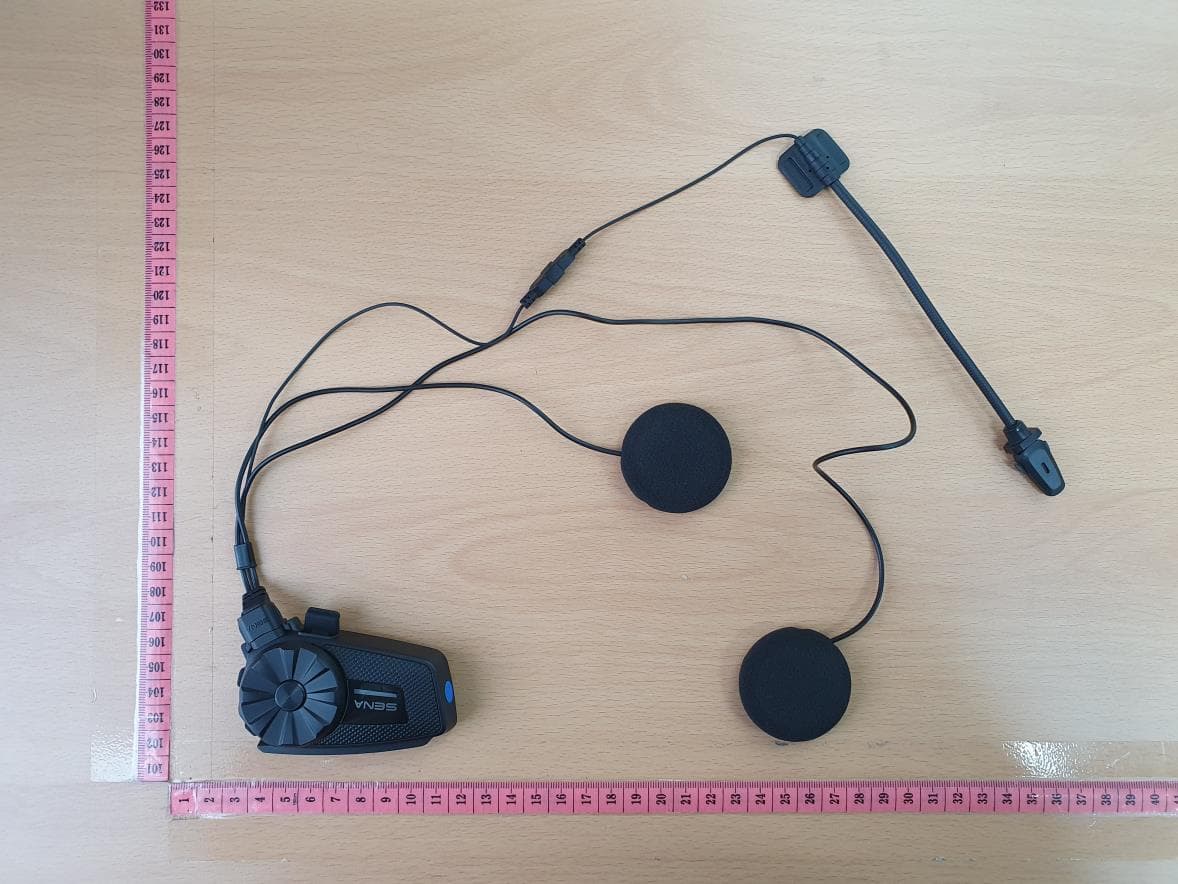
Click to zoom
Application Details
- Equipment Class
- DSS - Part 15 Spread Spectrum Transmitter
- Date of Grant
- Mar 04, 2021
- Application Purpose
- Original Equipment
- Date of Application
- Mar 04, 2021
- Equipment Note
- SPIDER ST1
- Frequency Range
- 2402.00000000 - 2480.00000000
- Company
- Sena Technologies Co., Ltd.
- Country
- South Korea
Documents & Files
Document Text
Text extracted from the exhibit documents filed with the FCC. Open a document above to read the original.
Users Manual
SPIDER ST1 Manual Charging Red LED: Charging Blue LED: Fully charged Power On/Off Press and hold the Jog Dial and Phone Button for 1 second Tap the Jog Dial and Phone Button. Volume Adjustment Increase/Decrease the volume : Rotate the Jog Dial clockwise or counterclockwise Battery Check Phone, Music Pairing Initially Pairing the SPIDER ST1 The headset will automatically enter the phone pairing mode when you initially turn on the headset or in the following situation: • Rebooting after executing Factory Reset 1. Press and hold the Jog Dial and Phone Button for 1 second. 2. Search for Bluetooth devices on your mobile phone. Select the SPIDER ST1 in the list of the devices detected on the mobile phone. 3. Enter 0000 for the PIN. Some mobile phones may not ask for the PIN. Music Operation Play or pause music: Press and hold the Jog Dial for 1 second. Track forward/ back: Rotate while pressing the Jog Dial clockwise or counterclockwise. Mobile Phone Call Making and Answering Answering a call: Tap the Phone Button Ending a call: Tap the Phone Button Voice dial: Tap the Phone Button Speed dial: Double tap the Phone Button Rejecting a call: Press and hold the Jog Dial for 2 seconds. Mesh Intercom Mesh Intercom On/Off : Tap the Mesh Button Radio On/Off Turn on the FM radio: Press the Phone Button for 1 second. Turn off the FM radio: Press the Phone Button for 1 second. Radio Scan Up FM Band Start scanning: Double tap the Phone Button Stop scanning: Double tap the Phone Button Save presets while scanning : Save presets: Tap the Phone Button Radio Move to Preset Station Move to next preset: Press the Jog Dial for 1 second (1 → 2 → ... → 10) Radio Seek Stations Seek up/down stations: Rotate while pressing the Jog Dial clockwise or counterclockwise. Setting Configuration Menu: Press the Jog Dial for 10 seconds. Using the Sena Device Manager Connect the headset to your computer via a USB cable. Launch the Sena Device Manager and click DEVICE SETTING to configure the headset settings. Troubleshooting Factory Reset If you want to restore the headset to factory default settings, use the Factory Reset in the configuration menu. The headset automatically restores the default settings and turns off. Certification and Safety Approvals FCC Compliance Statement This device complies with part 15 of the FCC rules. Operation is subject to the following two conditions: (1) This device may not cause harmful interference, and (2) This device must accept any interference received, including interference that may cause undesired operation. This equipment has been tested and found to comply with the limits for a Class B digital device pursuant to part 15 of the FCC rules. These limits are designed to provide reasonable protection against harmful interference in a residential installation. This equipment generates, uses and can radiate radio frequency energy and, if not installed and used in accordance with the instructions, may cause harmful interference to radio communications. However, there is no guarantee that interference will not occur in a particular installation. If this equipment does cause harmful interference to radio or television reception, which can be determined by turning the equipment on and off, the user is encouraged to try to correct the interference by one or more of the following measures: -Reorient or relocate the receiving antennae -Increase the separation between the equipment and the receiver -Connect the equipment into an outlet on a circuit different from that to which the receiver is connected. -Consult the dealer or an experienced radio/TV technician for help. FCC RF Exposure Statement This equipment complies with FCC radiation exposure limits set forth for an uncontrolled environment. End users must follow the specific operating instructions for satisfying RF exposure compliance. The antenna used for this transmitter must not transmit simultaneously with any other antenna or transmitter, except in accordance with FCC multi-transmitter product procedures. When equipped, the distance between antenna and one’s head surface is 40.5mm. FCC Caution Any changes or modifications to the equipment not expressly approved by the party responsible for compliance could void user’s authority to operate the equipment. Certification et homologation de sécurité Déclaration de conformité FCC Cet appareil est en conformité avec la partie 15 des règles de la FCC. Son fonctionnement est soumis aux deux conditions suivantes : (1) Cet appareil ne doit pas créer d’interférences préjudiciables et (2) Cet appareil doit accepter toutes les interférences reçues, y compris celles qui pourraient entraver son bon fonctionnement. Cet équipement a été testé et jugé conforme aux limites pour un appareil numérique de classe B, conformément à la partie 15 des règles de la FCC. Ces limites sont conçues pour fournir une protection raisonnable contre les interférences nuisibles dans une installation résidentielle. Cet équipement génère et utilise de l’énergie radio fréquence et, s’il n’est pas installé et utilisé conformément. aux instructions, il peut occasionner des interférences nuisibles au niveau des communications radios. Cependant, il n’existe aucune garantie que ces interférences ne se produiront pas dans une installation particulière. Si cet équipement génère des interférences nuisibles à la réception de la radio ou de la télévision (ce qu’il est possible de déterminer en mettant l’équipement hors tension, puis sous tension), l’utilisateur est invité à suivre une ou plusieurs des mesures suivantes pour corriger le problème des interférences en prenant l’une des mesures suivantes : -Modifier l’emplacement ou l’orientation de l’antenne de réception. -É loigner l’appareil du récepteur. -Brancher l’appareil sur une prise située sur un circuit différent de celui du récepteur. -Consulter le revendeur ou un technicien expérimenté pour obtenir de l’aide. É noncé FCC sur l’exposition aux radiations RF Cet équipement est conform…
Text truncated - open the document above for the full version.
Attestation Statements
SENA TECHNOLOGIES.Inc Mar 03 rd , 2021 Applicant: SENA TECHNOLOGIES.Inc FCC ID: S7A-SP88 / IC: 8154A-SP88 To. Whom it may concern: We, Sena Technologies,Inc. declare that when equipped, the distance between antenna and one’s head surface is 40.5mm. Seunghyun Kim, Research Engineer
Cover Letter(s)
SENA TECHNOLOGIES.Inc 19, Heolleung-ro 569-gil, Gangnam-gu, Seoul, South Korea Mar 04, 2021 FEDERAL COMMUNICATIONS COMMISSIONS Authorization and Evaluation Division 7435 Oakland Mills Road Columbia, MD 21046 Letter of Authorization We, the undersigned, hereby authorize Kenneth Kim of NCT Co.,Ltd. to act on our behalf in all manners relating to application for equipment authorization for FCC ID: S7A-SP88 / IC : 8154A-SP88 including signing of all documents relating to these matters. Any and all acts carried out by Kenneth Kim of NCT Co.,Ltd. on our behalf shall have the same affect as acts of our own. This authorization is valid until further written notice from SENA TECHNOLOGIES.Inc “I, the undersigned, hereby certify that we are not subject to a denial of federal benefits, that includes FCC benefits, pursuant to Section 5301 of the Anti-Drug Abuse Act of 1988, 21 U.S.C. 853(a).” Sincerely, Seunghyun KIM / Research Engineer
Cover Letter(s)
SENA TECHNOLOGIES.Inc 19, Heolleung-ro 569-gil, Gangnam-gu, Seoul, South Korea Federal Communications Commission Authorization and Evaluation Division Confidentiality Request regarding application for certification of FCC ID: S7A-SP88 Pursuant to Sections 0.457 and 0.459 of the Commission’s Rules, we hereby request confidential treatment of information accompanying this application as outlined below: Exhibit Type File Name Block Diagram Schematics Operational Description Part List [SP88] BLK [SP88] SCH [SP88] OpDes [SP88] Part List The above materials contain trade secrets and proprietary information not customarily released to the public. The public disclosure of these materials may be harmful to the applicant and provide unjustified benefits to its competitors. The applicant understands that pursuant to Section 0.457 of the Rules, disclosure of this application and all accompanying documentation will not be made before the date of the Grant for this application. In additional to above mentioned documents, in order to comply with the marketing regulations in Title 47 CFR §2.803 and the importation rules in Title 47 CFR §2.1204, while ensuring that business sensitive information remains confidential until the actual marketing of newly authorized devices, we request Short Term Confidentiality of the following attachment(s); Exhibit Type File Name External Photos Internal Photos Test Setup Photos Manual [SP88] EXT Photo [SP88] INT Photo [SP88] Test Setup Photo [SP88] Manual For 45 days, pursuant to Public Notice DA 04-1705. OR For 180 days pursuant to KDB 726920 D01. Sincerely, Seunghyun KIM / Research Engineer
External Photos
USB Port 1 (Charging port) USB Port 2 (Speaker and Mic port)
ID Label/Location Info
SENA_SP88_Label & Location Rear Side Label Location
Internal Photos
Internal BT Module BT Antenna MESH Antenna
RF Exposure Info
Model Name : FCC ID : (mm)(dBm)(dB)(dBm)(mW) 24027.788.787.553.00PASS 24417.638.637.293.00PASS 24807.258.256.683.00PASS 24026.437.435.533.00PASS 24416.367.365.453.00PASS 24806.037.035.053.00PASS 24026.667.665.833.00PASS 24416.597.595.743.00PASS 24806.377.375.463.00PASS 24023.794.793.013.00PASS 24424.035.033.183.00PASS 24804.015.013.173.00PASS 24109.9210.9212.363.00PASS 24459.6010.6011.483.00PASS 24759.0910.0910.213.00PASS (mm)(dBm)(mW) Bluetooth 24027.786.00 BT LE 24424.032.53 MESH 24109.929.82 0.40 PASS 0.093840.50 Min. Test separation distance Modulation Max. Power with tune-up tolerance Frequency (MHz) Simultaneous transmission SAR Test exclusion thresholds for 100MHz to 6GHz at test separation distance ≤ 50 mm (x=7.5) KDB 447498 - 3.4.2 b) When an antenna qualifies for the standalone SAR test exclusion of 4.3.1 and also transmits simultaneously with other antennas, the standalone SAR value must be estimated according to the following to determine the simultaneous transmission SAR test exclusion criteria:36 1) [(max. power of channel, including tune-up tolerance, mW) / (min. test separation distance, mm)]·[√f(GHz)/x] W/kg, for test separation distances ≤ 50 mm; where x = 7.5 for 1-g SAR and x = 18.75 for 10-g SAR. LimitResult 0.4738 0.4433 0.3966 BT LE 40.50± 1.00 0.1153 0.1229 0.1232 MESH 40.50± 1.00 8DPSK 40.50± 1.00 0.2233 0.2215 0.2122 π/4DQPSK 40.50± 1.00 0.2118 0.2101 0.1962 Standalone SAR Test exclusion thresholds for 100MHz to 6GHz at test separation distance ≤ 50 mm LimitResult GFSK 40.50± 1.00 0.2890 0.2814 0.2599 Modulation Frequency (MHz) Min. Test separation distance Measured Maximum Average power Tune-up tolerance Max. Power with tune-up tolerance S7A-SP88Separation distance : 40.5 mm MPE Calculation KDB 447498 - 3.4.1 a) For 100 MHz to 6 GHz and test separation distances ≤ 50 mm, the 1-g and 10-g SAR test exclusion thresholds are determined by the following: [(max. power of channel, including tune-up tolerance, mW) / (min. test separation distance, mm)] · [√f(GHz)] ≤ 3.0 for 1-g SAR, and ≤ 7.5 for 10-g extremity SAR, where - f(GHz) is the RF channel transmit frequency in GHz - Power and distance are rounded to the nearest mW and mm before calculation - The result is rounded to one decimal place for comparison SP88Device Category : Portable device
Test Report
Test Repot No.: NW2103-F001 211-71, Geumgok-ro, Hwaseong-si, Gyeonggi-do, Korea 18511 www.nct.re.kr TEL: +82-31-323-6070 FAX: +82-31-323-6071 Page 2 of 65 Table of contents 1. General Information -------------------------------------------------------------------------------- 2. Information’s about Test Item ------------------------------------------------------------------- 3. Test Report -------------------------------------------------------------------------------------------- 3.1 Test Summary ------------------------------------------------------------------------------------- 3.2 Test Report Version ----------------------------------------------------------------------------- 3.3 Transmitter Requirements 3.3.1 Antenna Requirement --------------------------------------------------------------------- 3.3.2 20 ㏈ Bandwidth & Occupied Bandwidth (99%) ----------------------------------- 3.3.3 Number of Hopping Frequencies ------------------------------------------------------- 3.3.4 Time of Occupancy (Dwell Time) ------------------------------------------------------- 3.3.5 Carrier Frequencies Separation -------------------------------------------------------- 3.3.6 Peak Output Power ------------------------------------------------------------------------ 3.3.7 TX Radiated Spurious Emission and Conducted Spurious Emission --------- 3.3.8 Conducted Emission ----------------------------------------------------------------------- APPENDIX APPENDIX I TEST SETUP ---------------------------------------------------------------------- APPENDIX II TEST EQUIPMENT USED FOR TESTS ---------------------------------- 3 3 5 5 6 7 8 15 18 20 24 31 59 62 64 Test Repot No.: NW2103-F001 211-71, Geumgok-ro, Hwaseong-si, Gyeonggi-do, Korea 18511 www.nct.re.kr TEL: +82-31-323-6070 FAX: +82-31-323-6071 Page 3 of 65 1. General Information’s 1.1 Test Performed Laboratory : NCT Co., Ltd. Address : 211-71, Geumgok-ro, Hwaseong-si, Gyeonggi-do, 18511, Korea Telephone : +82-31-323-6070 Facsimile : +82-31-323-6071 FCC Designation No. : KR0166 FCC Registration No. : 409631 IC Site Registration No. : 25897 2. Information’s about Test Item 2.1 Applicant Information Company name : SENA TECHNOLOGIES.Inc Address : 19, Heolleung-ro 569-gil, Gangnam-gu, Seoul, Korea Telephone / Facsimile : +82-2-571-8283 / +82-2-573-7710 2.2 Equipment Under Test (EUT) description Test item particulars : SPIDER ST1 Model and/or type reference : SP88 Additional model name : - Serial number : Prototype Antenna type and gain : Chip Antenna(M/N: SENA_009) with Max gain: 0.93 ㏈i Date (s) of performance of tests: : 2021-01-18 ~ 2021-02-16 Date of receipt of test item : 2021-01-11 EUT condition : Pre-production, not damaged Number of channel : 79 EUT Power Source : DC 3.7 V Type of Modulation : BDR Mode(GFSK), EDR Mode(Pi/4 DQPSK, 8DPSK) Firmware version : 1.0 Hardware version : 1.0 Test software name(version) : Qualcomm BlueSuite_BlueTest3(3.3.5) Test Repot No.: NW2103-F001 211-71, Geumgok-ro, Hwaseong-si, Gyeonggi-do, Korea 18511 www.nct.re.kr TEL: +82-31-323-6070 FAX: +82-31-323-6071 Page 4 of 65 2.3 Tested Frequency Test Mode Test frequency (㎒) Low frequency Middle frequency High frequency GFSK 2 402 2 441 2 480 Pi/4 DQPSK 2 402 2 441 2 480 8DPSK 2 402 2 441 2 480 2.4 Used Test Software Setting Value Test Mode Setting Item Atn Mag Exp GFSK 0 7 0 Pi/4 DQPSK 0 4 0 8DPSK 0 4 0 2.5 Worst-Case BDR GFSK(DH5) EDR 8DPSK(3-DH5) Note: The power measurement has been conducted to determine the worst-case mode from all possible combinations between available modulations, data rates. Test Repot No.: NW2103-F001 211-71, Geumgok-ro, Hwaseong-si, Gyeonggi-do, Korea 18511 www.nct.re.kr TEL: +82-31-323-6070 FAX: +82-31-323-6071 Page 5 of 65 3. Test Report 3.1 Test Summary Applied FCC Rule IC Rule Test Items Test Condition Result 15.203 - Antenna Requirement Conducted C 15.247(a) - 20 ㏈ Bandwidth C - RSS GEN (6.7) Occupied Bandwidth (99%) C 15.247(a) RSS-247 (5.1) Number of Hopping Frequencies C 15.247(a) RSS-247 (5.1) Time of Occupancy (Dwell Time) C 15.247(a) RSS-247 (5.1) Carrier Frequencies Separation C 15.247(b) RSS-247 (5.4) Peak Output Power C 15.247(d) RSS-247 (5.5) Conducted Spurious Emission C 15.247(d) 15.205 & 15.209 RSS-247 (5.5) RSS-GEN (8.9 & 8.10) Radiated Spurious Emission Radiated C 15.207 RSS-GEN (8.8) Conducted Emissions AC Line Conducted C Note 1: C=Complies NC=Not Complies NT=Not Tested NA=Not Applicable The sample was tested according to the following specification: ANSI C63.10:2013. Compliance was determined by specification limits of the applicable standard according to customer requirements. Test Repot No.: NW2103-F001 211-71, Geumgok-ro, Hwaseong-si, Gyeonggi-do, Korea 18511 www.nct.re.kr TEL: +82-31-323-6070 FAX: +82-31-323-6071 Page 6 of 65 3.2 Test Report Version Test Report No. Date Description NW2103-F001 2021-03-03 Initial issue Test Repot No.: NW2103-F001 211-71, Geumgok-ro, Hwaseong-si, Gyeonggi-do, Korea 18511 www.nct.re.kr TEL: +82-31-323-6070 FAX: +82-31-323-6071 Page 7 of 65 3.3 Transmitter Requirements 3.3.1 Antenna Requirement Accoding to §15.203 An intentional radiator shall be designed to ensure that no antenna other than that furnished by the responsible party shall be used with the device. The use of a permanently attached antenna or of an antenna that uses a unique coupling to the intentional radiator shall be considered sufficient to comply with the provisions of this section. The manufacturer may design the unit so that a broken antenna can be replaced by the user, but the use of a standard antenna jack or electrical connector is prohibited. Accoding to §15.247(b)(4) e conducted output power limit specified in paragraph (b) of this section is based on the use of antennas with directional gains that do not exceed 6 ㏈i. Except as shown in paragraph (c) of this section, if transmitting antennas of directional gain greater than 6 ㏈i are used, the conducted output power from the intentional radiator shall be reduced below t…
Text truncated - open the document above for the full version.
Test Setup Photos
Below 30 MHz Below 1 GHz Above 1 GHz Conducted Emission
Contact Information
Applicant
Seunghyun KIM(Research Engineer)
Test Firm
NCT Co., Ltd.Il-Shin Kim
Technical Specifications
| # | Rule Parts | Frequency Range | Power Output |
|---|---|---|---|
| 1 | 15C | 2.40 GHz - 2.48 GHz | 8.20 mW |
Other Applications from Sena Technologies Co., Ltd.
S7A-SP196
Jun 15, 2026Wireless Communication Systems
Equipment Class
NII - Unlicensed National Information Infrastructure TXS7A-SP198
May 07, 2026Wireless Communication Systems
Equipment Class
DTS - Digital Transmission SystemS7A-SP197
Apr 06, 2026Wireless Communication Systems
Equipment Class
DTS - Digital Transmission SystemS7A-SP195
Apr 06, 2026Wireless Communication Systems
Equipment Class
DTS - Digital Transmission SystemS7A-SP158
Mar 13, 2026Wireless Communication Systems
Equipment Class
DSS - Part 15 Spread Spectrum Transmitter