S7APARANIMSP100Bluetooth IP Gateway
Sena Technologies Co., Ltd.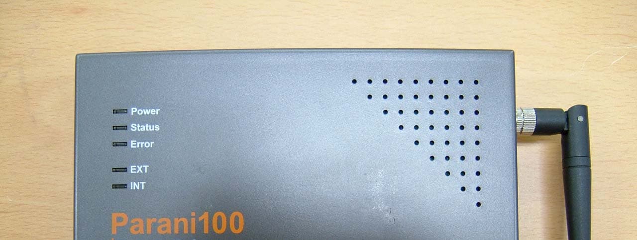
Click to zoom
Application Details
- Equipment Class
- DSS - Part 15 Spread Spectrum Transmitter
- Date of Grant
- Sep 21, 2006
- Application Purpose
- Original Equipment
- Date of Application
- Sep 20, 2006
- Equipment Note
- Bluetooth IP Gateway
- Frequency Range
- 2402.00000000 - 2480.00000000
- Company
- Sena Technologies Co., Ltd.
- Country
- South Korea
Documents & Files
Document Text
Text extracted from the exhibit documents filed with the FCC. Open a document above to read the original.
Users Manual
1 Copyright © 2006 Sena Technologies, Inc. All rights reserved. by Bluetooth Enabling Wireless Serial Communications Parani-MSP100 User Guide Version 1.0.0 (2006.08.20) For Wireless Multi-Serial Communications, based on Bluetooth Technology 2 Copyright © 2006 Sena Technologies, Inc. All rights reserved. Contents 1. ABOUT PARANI-MSP™ ......................................................................................................................4 1.1 EXTERNAL VIEW................................................................................................................................6 1.2 LED INDICATORS...............................................................................................................................8 2. INSTALLATION ....................................................................................................................................9 2.1 NETWORK SETTINGS.......................................................................................................................10 2.2 LAN ACCESS PROFILE....................................................................................................................13 2.3 FIRMWARE DOWNLOAD...................................................................................................................14 2.4 SERIAL PORT....................................................................................................................................17 2.5 RESET/REBOOT/QUIT......................................................................................................................19 3. CONFIGURATION .............................................................................................................................20 3.1 CONFIGURATION VIA PARANI-MSP SOFTWARE..............................................................................20 3.1.1 When Parani-MSP is connected to PC directly.....................................................................20 3.1.2 Log in Parani-MSP software...................................................................................................21 3.1.2 Operation Mode.......................................................................................................................22 3.1.3 Bluetooth..................................................................................................................................29 3.1.4 Connections..............................................................................................................................30 3.1.5 Neighborhoods.........................................................................................................................31 3.1.6 Repeater...................................................................................................................................31 3.1.7 MSP information.....................................................................................................................32 4. OPERATION MODE...........................................................................................................................34 4.1 SERVER MODE.................................................................................................................................34 4.2 CLIENT MODE..................................................................................................................................35 4.3 VERTEX MODE.................................................................................................................................35 4.4 REPEATER MODE.............................................................................................................................36 4.5 SERIAL HUB MODE..........................................................................................................................37 4.6 RS232 MODE....................................................................................................................................38 5. CONTROL COMMANDS...................................................................................................................41 5.1 BASIC COMMANDS...........................................................................................................................43 5.2 COMMANDS FOR SERVER MODE.....................................................................................................43 5.3 COMMANDS FOR CLIENT MODE......................................................................................................45 3 Copyright © 2006 Sena Technologies, Inc. All rights reserved. 5.4 COMMANDS FOR VERTEX MODE.....................................................................................................46 5.5 COMMANDS FOR SERIAL HUB MODE..............................................................................................46 5.6 COMMANDS FOR REPEATER MODE.................................................................................................47 5.7 COMMANDS FOR BLUETOOTH CONFIGURATION............................................................................47 5.8 COMMANDS FOR BLUETOOTH CONNECTION MANAGEMENT........................................................50 5.9 OTHER COMMANDS.........................................................................................................................53 6. AT COMMAND INTERFACE............................................................................................................55 7. CONFIGURATION VIA WEB ...........................................................................................................59 7.1 MSP CONFIGURATION.....................................................................................................................59 7.2 MODE CONFIGURATION...................................................................................................................61 7.3 IP ASSIGNMENT......................................…
Text truncated - open the document above for the full version.
Cover Letter(s)
Sena Technologies, Inc. 210 Yangjae-dong Seocho-gu Seoul 137-130 Korea Tel. +82-2-571-8283 Fax +82-2-573-7710 September 11, 2006 Federal Communications Commission Equipment Authorization Branch 7435 Oakland Mills Road Columbia, MD 21046 In re : Sena Technologies, Inc. FCC ID : S7APARANIMSP100 Request for Confidentiality Gentlemen: Pursuant to Sections 0.457 and 0.459 of the Commission’s Rules, we hereby request confidential treatment of information accompanying this application as outlined below: Schematics, Parts list, Block diagram and Operational description. The above materials contain trade secrets and proprietary information not customarily released to the public. The public disclosure of these materials may be harmful to the applicant and provide unjustified benefits to its competitors. The applicant understands that pursuant to Section 0.457 of the Rules, disclosure of this application and all accompanying documentation will not be made before the date of the Grant for this application. Sincerely, __________________________ Seung – Hyun Kim Associate Research Engineer
Cover Letter(s)
Sena Technologies, Inc. 210 Yangjae-dong Seocho-gu Seoul 137-130 Korea Tel. +82-2-571-8283 Fax +82-2-573-7710 September 11, 2006 Federal Communications Commission Equipment Authorization Branch 7435 Oakland Mills Road Columbia, MD 21046 In re : Sena Technologies, Inc. FCC ID : S7APARANIMSP100 Request for Short-Term Confidentiality Gentlemen: In accordance with 0.459 of CFR 47, Sena Technologies, Inc. requests short-term Confidentiality of following sections of this application for a period of 45 days after grant is issued. Test setup photos External photos Internal photos, and User’s manual These documents contain detailed system and equipment descriptions and related information about the product, which Sena Technologies, Inc. considers to be proprietary, confidential, and a custom design and otherwise, would not release to the general public. Since this design is a basis from which future technological products will evolve, Sena Technologies, Inc. feels that this information would be of benefit to its competitors, and that the disclosure of the information in these documents would give our competitors an unfair advantage in the market. Sincerely, __________________________ Seung – Hyun Kim Associate Research Engineer
External Photos
FCC ID: S7APARANIMSP100 Copyright ○ c 2006, LTA Co., Ltd. Page 1 of 3 FCC ID: S7APARANIMSP100 Copyright ○ c 2006, LTA Co., Ltd. Page 2 of 3 FCC ID: S7APARANIMSP100 Copyright ○ c 2006, LTA Co., Ltd. Page 3 of 3
ID Label/Location Info
FCC ID: S7APARANIMSP100 Copyright Ⓒ 2006, LTA Co., Ltd. SAMPLE LABEL & LOCATION Label SENA FCC ID:S7APARANIMSP100 M/N: Parani-MSP100 This device complies with part 15 of the FCC Rules. Operation is subject to the following two conditions: This device may not cause harmful interference, and This device must accept any interference received, Including interference that may cause undesired operation. Made in Korea
Internal Photos
FCC ID: S7APARANIMSP100 Copyright ○ c 2006, LTA Co., Ltd. Page 1 of 2 FCC ID: S7APARANIMSP100 Copyright ○ c 2006, LTA Co., Ltd. Page 2 of 2
RF Exposure Info
ATTACHMENT FCC ID: S7APARANIMSP100 ** MPE Calculations ** The EUT will only be used with a separation of 20 centimeters or greater between the antenna and the body of the user. The MPE calculation for this exposure is shown below. The peak radiated output power (EIRP) is calculated as follows: EIRP = P + G EIRP = 16.17 dBm + 1.98dBi EIRP = 18.15 dBm Where, P = Power input to the antenna (mW) G = Power gain of the antenna (dBi) Power density at the specific separation: S = PG/(4R 2 π) S = (41.4 * 1.58) / (4 * 20 2 * π) S = 0.013 mW/cm 2 Where, S = Maximum power density (mW/cm 2 ) P = Power input to the antenna (mW) G = Numeric power gain of the antenna R = Distance to the center of the radiation of the antenna (20cm = limit for MPE) The Maximum permissible exposure (MPE) for the general population is 1 mW/cm 2 . The power density at 20cm does not exceed the 1 mW/cm 2 limit. Therefore, the exposure condition is compliant with FCC rules. Estimated safe separation: R = √(PG / 4π) R = √(41.4 * 1.98 / 4π) R = 2.28 cm Where, P = Power input to the antenna (mW) G = Numeric power gain of the antenna R = Distance to the center of the radiation of the antenna (20cm = limit for MPE) The numeric gain(G) of the antenna with a gain specified in dB is determined by: G = Log -1 (dB antenna gain / 10) G = Log -1 (1.98 / 10) G = 1.58
Test Setup Photos
FCC ID: S7APARANIMSP100 Copyright Ⓒ 2006, LTA Co., Ltd. Radiated Emission – unwanted signal FCC ID: S7APARANIMSP100 Copyright Ⓒ 2006, LTA Co., Ltd. Radiated Emission – wanted signal FCC ID: S7APARANIMSP100 Copyright Ⓒ 2006, LTA Co., Ltd. Conducted Emission
Contact Information
Applicant
Seunghyun KIM(Research Engineer)
Test Firm
LTA Co.,LtdAhn Chulho
Technical Specifications
| # | Rule Parts | Frequency Range | Power Output |
|---|---|---|---|
| 1 | 15C | 2.40 GHz - 2.48 GHz | 40.00 mW |
Other Applications from Sena Technologies Co., Ltd.
S7A-SP196
Jun 15, 2026Wireless Communication Systems
Equipment Class
NII - Unlicensed National Information Infrastructure TXS7A-SP198
May 07, 2026Wireless Communication Systems
Equipment Class
DTS - Digital Transmission SystemS7A-SP197
Apr 06, 2026Wireless Communication Systems
Equipment Class
DTS - Digital Transmission SystemS7A-SP195
Apr 06, 2026Wireless Communication Systems
Equipment Class
DTS - Digital Transmission SystemS7A-SP158
Mar 13, 2026Wireless Communication Systems
Equipment Class
DSS - Part 15 Spread Spectrum Transmitter