S7APSX10WSERIAL DEVICE SERVER
Sena Technologies Co., Ltd.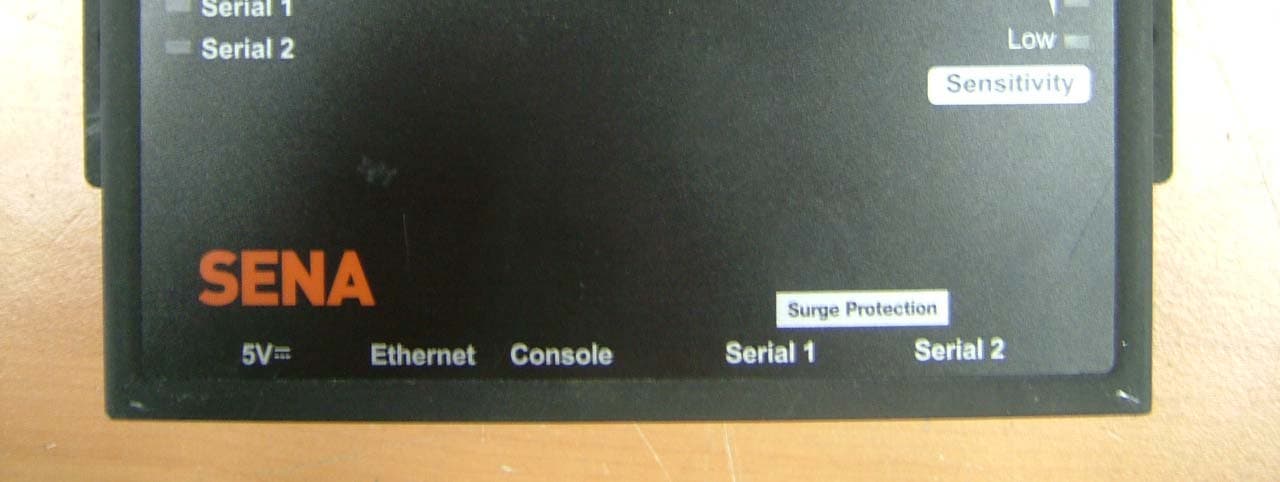
Click to zoom
Application Details
- Equipment Class
- DTS - Digital Transmission System
- Date of Grant
- Jan 14, 2008
- Application Purpose
- Original Equipment
- Date of Application
- Jan 13, 2008
- Equipment Note
- SERIAL DEVICE SERVER
- Frequency Range
- 2412.00000000 - 2462.00000000
- Company
- Sena Technologies Co., Ltd.
- Country
- South Korea
Documents & Files
Document Text
Text extracted from the exhibit documents filed with the FCC. Open a document above to read the original.
Users Manual
Universal Device Servers HelloDevice Pro Series (PS110W/210W) User Guide Version 1.0.1 2007-12-21 메모 [..1]: 삭제됨: 1 삭제됨: 2 삭제됨: 0 삭제됨: 0 삭제됨: 1 삭제됨: 2 2 Copyright Information Copyright 1998-2007, Sena Technologies, Inc. All rights reserved. Sena Technologies reserves the right to make any changes and improvements to its product without providing prior notice. Trademark Information HelloDevice™ is a trademark of Sena Technologies, Inc. Windows® is a registered trademark of Microsoft Corporation. Ethernet® is a registered trademark of XEROX Corporation. Notice to Users Proper back-up systems and necessary safety devices should be utilized to protect against injury, death or property damage due to system failure. Such protection is the responsibility of the user. This device is not approved for use as a life-support or medical system. Any changes or modifications made to this device without the explicit approval or consent of Sena Technologies will void Sena Technologies of any liability or responsibility of injury or loss caused by any malfunction. Technical Support Sena Technologies, Inc. 210 Yangjae-dong, Seocho-gu Seoul 137-130, Korea Tel: (+82-2) 573-5422 Fax: (+82-2) 573-7710 E-Mail: [email protected] Website: http://www.sena.com 삭제됨: 5 삭제됨: 삭제됨: 삭제됨: 삭제됨: 3 Revision history Revision Date Name Description V1.0.0 2007-09-09 Y. Moon First release V1.0.1 2007-12-21 Y. Moon A.1.2, A.1.4 4 Contents 1. Introduction 7 1.1. Overview .................................................................................................................................... 7 1.2. Package Check List.................................................................................................................... 8 1.3. Product Specification.................................................................................................................. 9 1.4. Terminologies and acronyms ................................................................................................... 10 2. Getting Started 12 2.1. Panel Layout ............................................................................................................................ 12 2.1.1. PS110W Panel Layout................................................................................................... 12 2.1.2. PS210W Panel Layout................................................................................................... 13 2.2. Connecting the Hardware ........................................................................................................14 2.2.1. Connecting to the network ............................................................................................. 14 2.2.2. Connecting to the device ............................................................................................... 15 2.2.3. Connecting the power ....................................................................................................16 2.2.4. Accessing the System Console ..................................................................................... 16 2.2.5. Using the System console ............................................................................................. 17 2.2.6. Using Remote console................................................................................................... 19 2.3. Accessing the Web Browser Management Interface ............................................................... 20 3. Network Configuration 23 3.1. IP Configuration........................................................................................................................ 23 3.1.1. Interfaces ....................................................................................................................... 24 3.1.2. Using a Static IP Address...............................................................................................24 3.1.3. Using DHCP...................................................................................................................25 3.2. WiFi Configuration.................................................................................................................... 26 3.2.1. Network type .................................................................................................................. 26 3.2.2. Operation mode configuration........................................................................................ 26 3.2.3. List of APs ...................................................................................................................... 27 3.2.4. Neighborhood APs .........................................................................................................28 3.2.5. Adhoc configuration ....................................................................................................... 28 3.3. SNMP Configurations............................................................................................................... 30 3.3.1. MIB-II System objects Configuration.............................................................................. 31 3.3.2. Access Control Configuration......................................................................................... 31 3.3.3. Trap Receiver Configuration .......................................................................................... 31 3.3.4. Management using SNMP ............................................................................................. 32 3.4. Dynamic DNS Configuration .................................................................................................... 33 3.5. SMTP Configuration ................................................................................................................. 34 3.6. IP Filtering ................................................................................................................................ 35 5 3.7. SYSLOG server configuration......................................…
Text truncated - open the document above for the full version.
Users Manual
Universal Device Servers HelloDevice Pro Series (PS110W/210W) User Guide Version 1.0.1 2007-12-21 메모 [..1]: 삭제됨: 1 삭제됨: 2 삭제됨: 0 삭제됨: 0 삭제됨: 1 삭제됨: 2 2 Copyright Information Copyright 1998-2007, Sena Technologies, Inc. All rights reserved. Sena Technologies reserves the right to make any changes and improvements to its product without providing prior notice. Trademark Information HelloDevice™ is a trademark of Sena Technologies, Inc. Windows® is a registered trademark of Microsoft Corporation. Ethernet® is a registered trademark of XEROX Corporation. Notice to Users Proper back-up systems and necessary safety devices should be utilized to protect against injury, death or property damage due to system failure. Such protection is the responsibility of the user. This device is not approved for use as a life-support or medical system. Any changes or modifications made to this device without the explicit approval or consent of Sena Technologies will void Sena Technologies of any liability or responsibility of injury or loss caused by any malfunction. Technical Support Sena Technologies, Inc. 210 Yangjae-dong, Seocho-gu Seoul 137-130, Korea Tel: (+82-2) 573-5422 Fax: (+82-2) 573-7710 E-Mail: [email protected] Website: http://www.sena.com 삭제됨: 5 삭제됨: 삭제됨: 삭제됨: 삭제됨: 3 Revision history Revision Date Name Description V1.0.0 2007-09-09 Y. Moon First release V1.0.1 2007-12-21 Y. Moon A.1.2, A.1.4 4 Contents 1. Introduction 7 1.1. Overview .................................................................................................................................... 7 1.2. Package Check List.................................................................................................................... 8 1.3. Product Specification.................................................................................................................. 9 1.4. Terminologies and acronyms ................................................................................................... 10 2. Getting Started 12 2.1. Panel Layout ............................................................................................................................ 12 2.1.1. PS110W Panel Layout................................................................................................... 12 2.1.2. PS210W Panel Layout................................................................................................... 13 2.2. Connecting the Hardware ........................................................................................................14 2.2.1. Connecting to the network ............................................................................................. 14 2.2.2. Connecting to the device ............................................................................................... 15 2.2.3. Connecting the power ....................................................................................................16 2.2.4. Accessing the System Console ..................................................................................... 16 2.2.5. Using the System console ............................................................................................. 17 2.2.6. Using Remote console................................................................................................... 19 2.3. Accessing the Web Browser Management Interface ............................................................... 20 3. Network Configuration 23 3.1. IP Configuration........................................................................................................................ 23 3.1.1. Interfaces ....................................................................................................................... 24 3.1.2. Using a Static IP Address...............................................................................................24 3.1.3. Using DHCP...................................................................................................................25 3.2. WiFi Configuration.................................................................................................................... 26 3.2.1. Network type .................................................................................................................. 26 3.2.2. Operation mode configuration........................................................................................ 26 3.2.3. List of APs ...................................................................................................................... 27 3.2.4. Neighborhood APs .........................................................................................................28 3.2.5. Adhoc configuration ....................................................................................................... 28 3.3. SNMP Configurations............................................................................................................... 30 3.3.1. MIB-II System objects Configuration.............................................................................. 31 3.3.2. Access Control Configuration......................................................................................... 31 3.3.3. Trap Receiver Configuration .......................................................................................... 31 3.3.4. Management using SNMP ............................................................................................. 32 3.4. Dynamic DNS Configuration .................................................................................................... 33 3.5. SMTP Configuration ................................................................................................................. 34 3.6. IP Filtering ................................................................................................................................ 35 5 3.7. SYSLOG server configuration......................................…
Text truncated - open the document above for the full version.
Cover Letter(s)
Sena Technologies, Inc. 210 Yangjae-dong Seocho-gu Seoul 137-130 Korea Tel. +82-2-571-8283 Fax +82-2-573-7710 December 29, 2007 Federal Communications Commission Equipment Authorization Branch 7435 Oakland Mills Road Columbia, MD 21046 In re : Sena Technologies, Inc. FCC ID : S7APSX10W Request for Confidentiality Gentlemen: Pursuant to Sections 0.457 and 0.459 of the Commission’s Rules, we hereby request confidential treatment of information accompanying this application as outlined below: Schematics (File name: [S7APSX10W] SCH.pdf), Parts list(File name: [S7APSX10W] PL.pdf), Block diagram (File name: [S7APSX10W] BLK.pdf), and Operational description (File name: [S7APSX10W] Op Des.pdf). The above materials contain trade secrets and proprietary information not customarily released to the public. The public disclosure of these materials may be harmful to the applicant and provide unjustified benefits to its competitors. The applicant understands that pursuant to Section 0.457 of the Rules, disclosure of this application and all accompanying documentation will not be made before the date of the Grant for this application. Sincerely, YoungSam, KIM
Cover Letter(s)
Sena Technologies, Inc. 210 Yangjae-dong Seocho-gu Seoul 137-130 Korea Tel. +82-2-571-8283 Fax +82-2-573-7710 January 9, 2008 Federal Communications Commission Equipment Authorization Branch 7435 Oakland Mills Road Columbia, MD 21046 In re : Sena Technologies, Inc. FCC ID : S7APSX10W Cover letter Gentlemen: The product have the WLAN module. The module is already authorized under FCC ID:MQ4WCM6002 . The WLAN module is approved the dipole antenna with 2dBi Gain. But the new host device is changed the helical antenna with 5dBi. So, We additionally tested the radiated emission and radiated spurious emission. This approved module was originally approved as a composite device3 for use in the 2.4 GHz and 5.7GHz operation under FCC Part 15.247 and 5.1GHz operation for use under FCC Rule Part 15.401 for a UNII approval. But These other bands(5.7GHz and 5.1GHz Bands) are not operational and have been removed from service from operation in this new Host configuration. The digital/computer portion of the device was authorized under the Declaration Conformity procedure. Sincerely, YoungSam, KIM
Cover Letter(s)
Sena Technologies, Inc. 210 Yangjae-dong Seocho-gu Seoul 137-130 Korea Tel. +82-2-571-8283 Fax +82-2-573-7710 December 29, 2007 Federal Communications Commission Equipment Authorization Branch 7435 Oakland Mills Road Columbia, MD 21046 In re : Sena Technologies, Inc. FCC ID : S7APSX10W Request for Confidentiality Gentlemen: Pursuant to Sections 0.457 and 0.459 of the Commission’s Rules, we hereby request confidential treatment of information accompanying this application as outlined below: Schematics (File name: [S7APSX10W] SCH.pdf), Parts list(File name: [S7APSX10W] PL.pdf), Block diagram (File name: [S7APSX10W] BLK.pdf), and Operational description (File name: [S7APSX10W] Op Des.pdf). The above materials contain trade secrets and proprietary information not customarily released to the public. The public disclosure of these materials may be harmful to the applicant and provide unjustified benefits to its competitors. The applicant understands that pursuant to Section 0.457 of the Rules, disclosure of this application and all accompanying documentation will not be made before the date of the Grant for this application. Sincerely, YoungSam, KIM
Cover Letter(s)
Sena Technologies, Inc. 210 Yangjae-dong Seocho-gu Seoul 137-130 Korea Tel. +82-2-571-8283 Fax +82-2-573-7710 January 9, 2008 Federal Communications Commission Equipment Authorization Branch 7435 Oakland Mills Road Columbia, MD 21046 In re : Sena Technologies, Inc. FCC ID : S7APSX10W Cover letter Gentlemen: The product have the WLAN module. The module is already authorized under FCC ID:MQ4WCM6002 . The WLAN module is approved the dipole antenna with 2dBi Gain. But the new host device is changed the helical antenna with 5dBi. So, We additionally tested the radiated emission and radiated spurious emission. This approved module was originally approved as a composite device3 for use in the 2.4 GHz and 5.7GHz operation under FCC Part 15.247 and 5.1GHz operation for use under FCC Rule Part 15.401 for a UNII approval. But These other bands(5.7GHz and 5.1GHz Bands) are not operational and have been removed from service from operation in this new Host configuration. The digital/computer portion of the device was authorized under the Declaration Conformity procedure. Sincerely, YoungSam, KIM
External Photos
FCC ID:S7APSX10W Copyright ○ c 2007, LTA Co., Ltd. Page 1 of 7 FCC ID:S7APSX10W Copyright ○ c 2007, LTA Co., Ltd. Page 2 of 7 FCC ID:S7APSX10W Copyright ○ c 2007, LTA Co., Ltd. Page 3 of 7 FCC ID:S7APSX10W Copyright ○ c 2007, LTA Co., Ltd. Page 4 of 7 ANTENNA- M/N: R-AN2400-1901RS FCC ID:S7APSX10W Copyright ○ c 2007, LTA Co., Ltd. Page 5 of 7 ANTENNA- M/N: R-AN2400-5801RS FCC ID:S7APSX10W Copyright ○ c 2007, LTA Co., Ltd. Page 6 of 7 Model Description-External Photograph M/N: PS210W ; with Serial Port 2ea FCC ID:S7APSX10W Copyright ○ c 2007, LTA Co., Ltd. Page 7 of 7 Model Description-External Photograph M/N: PS110W ; with Serial Port 1ea
External Photos
FCC ID:S7APSX10W Copyright ○ c 2007, LTA Co., Ltd. Page 1 of 7 FCC ID:S7APSX10W Copyright ○ c 2007, LTA Co., Ltd. Page 2 of 7 FCC ID:S7APSX10W Copyright ○ c 2007, LTA Co., Ltd. Page 3 of 7 FCC ID:S7APSX10W Copyright ○ c 2007, LTA Co., Ltd. Page 4 of 7 ANTENNA- M/N: R-AN2400-1901RS FCC ID:S7APSX10W Copyright ○ c 2007, LTA Co., Ltd. Page 5 of 7 ANTENNA- M/N: R-AN2400-5801RS FCC ID:S7APSX10W Copyright ○ c 2007, LTA Co., Ltd. Page 6 of 7 Model Description-External Photograph M/N: PS210W ; with Serial Port 2ea FCC ID:S7APSX10W Copyright ○ c 2007, LTA Co., Ltd. Page 7 of 7 Model Description-External Photograph M/N: PS110W ; with Serial Port 1ea
ID Label/Location Info
SAMPLE LABEL & LOCATION SENA FCC ID: S7APSX10W This device complies with part 15 of the FCC Rules. Operation is subject to the following two conditions: This device may not cause harmful interference, and This device must accept any interference received, Including interference that may cause undesired operation.
ID Label/Location Info
SAMPLE LABEL & LOCATION SENA FCC ID: S7APSX10W This device complies with part 15 of the FCC Rules. Operation is subject to the following two conditions: This device may not cause harmful interference, and This device must accept any interference received, Including interference that may cause undesired operation.
Internal Photos
FCC ID:S7APSX10W Copyright ○ c 2007, LTA Co., Ltd. Page 1 of 7 PS210W Internal Photo PS110W Internal Photo FCC ID:S7APSX10W Copyright ○ c 2007, LTA Co., Ltd. Page 2 of 7 PS210W Front Board Photo PS210W Rear Board Photo FCC ID:S7APSX10W Copyright ○ c 2007, LTA Co., Ltd. Page 3 of 7 PS110W Front Board Photo PS110W Rear Board Photo FCC ID:S7APSX10W Copyright ○ c 2007, LTA Co., Ltd. Page 4 of 7 WLAN Front Board Photo WLAN Rear Board Photo FCC ID:S7APSX10W Copyright ○ c 2007, LTA Co., Ltd. Page 5 of 7 WLAN Inside Board Photo FCC ID:S7APSX10W Copyright ○ c 2007, LTA Co., Ltd. Page 6 of 7 Model Description-Internal Photograph M/N: PS210W ; with Serial Port 2ea FCC ID:S7APSX10W Copyright ○ c 2007, LTA Co., Ltd. Page 7 of 7 Model Description-Internal Photograph M/N: PS110W ; with Serial Port 1ea
Internal Photos
FCC ID:S7APSX10W Copyright ○ c 2007, LTA Co., Ltd. Page 1 of 7 PS210W Internal Photo PS110W Internal Photo FCC ID:S7APSX10W Copyright ○ c 2007, LTA Co., Ltd. Page 2 of 7 PS210W Front Board Photo PS210W Rear Board Photo FCC ID:S7APSX10W Copyright ○ c 2007, LTA Co., Ltd. Page 3 of 7 PS110W Front Board Photo PS110W Rear Board Photo FCC ID:S7APSX10W Copyright ○ c 2007, LTA Co., Ltd. Page 4 of 7 WLAN Front Board Photo WLAN Rear Board Photo FCC ID:S7APSX10W Copyright ○ c 2007, LTA Co., Ltd. Page 5 of 7 WLAN Inside Board Photo FCC ID:S7APSX10W Copyright ○ c 2007, LTA Co., Ltd. Page 6 of 7 Model Description-Internal Photograph M/N: PS210W ; with Serial Port 2ea FCC ID:S7APSX10W Copyright ○ c 2007, LTA Co., Ltd. Page 7 of 7 Model Description-Internal Photograph M/N: PS110W ; with Serial Port 1ea
RF Exposure Info
ATTACHMENT FCC ID: S7APSX10W ** MPE Calculations ** The EUT will only be used with a separation of 20 centimeters or greater between the antenna and the body of the user. The MPE calculation for this exposure is shown below. The peak radiated output power (EIRP) is calculated as follows: EIRP = P + G EIRP = 18.8 dBm + 5dBi EIRP = 23.8 dBm Where, P = Power input to the antenna (mW) G = Power gain of the antenna (dBi) Power density at the specific separation: S = PG/(4R 2 π) S = (75.86 * 3.16) / (4 * 202 * π) S = 0.0477 mW/cm2 Where, S = Maximum power density (mW/cm 2 ) P = Power input to the antenna (mW) G = Numeric power gain of the antenna R = Distance to the center of the radiation of the antenna (20cm = limit for MPE) The Maximum permissible exposure (MPE) for the general population is 1 mW/cm 2 . The power density at 20cm does not exceed the 1 mW/cm 2 limit. Therefore, the exposure condition is compliant with FCC rules. Estimated safe separation: R = √(PG / 4π) R = √(75.86 * 3.16 / 4π) R = 4.37Cm Where, P = Power input to the antenna (mW) G = Numeric power gain of the antenna R = Distance to the center of the radiation of the antenna (20cm = limit for MPE) The numeric gain(G) of the antenna with a gain specified in dB is determined by: G = Log -1 (dB antenna gain / 10) G = Log -1 (5 / 10) G = 3.16
RF Exposure Info
ATTACHMENT FCC ID: S7APSX10W ** MPE Calculations ** The EUT will only be used with a separation of 20 centimeters or greater between the antenna and the body of the user. The MPE calculation for this exposure is shown below. The peak radiated output power (EIRP) is calculated as follows: EIRP = P + G EIRP = 18.8 dBm + 5dBi EIRP = 23.8 dBm Where, P = Power input to the antenna (mW) G = Power gain of the antenna (dBi) Power density at the specific separation: S = PG/(4R 2 π) S = (75.86 * 3.16) / (4 * 202 * π) S = 0.0477 mW/cm2 Where, S = Maximum power density (mW/cm 2 ) P = Power input to the antenna (mW) G = Numeric power gain of the antenna R = Distance to the center of the radiation of the antenna (20cm = limit for MPE) The Maximum permissible exposure (MPE) for the general population is 1 mW/cm 2 . The power density at 20cm does not exceed the 1 mW/cm 2 limit. Therefore, the exposure condition is compliant with FCC rules. Estimated safe separation: R = √(PG / 4π) R = √(75.86 * 3.16 / 4π) R = 4.37Cm Where, P = Power input to the antenna (mW) G = Numeric power gain of the antenna R = Distance to the center of the radiation of the antenna (20cm = limit for MPE) The numeric gain(G) of the antenna with a gain specified in dB is determined by: G = Log -1 (dB antenna gain / 10) G = Log -1 (5 / 10) G = 3.16
Schematics
Ref. No.: LR500190710A Copyright ○ c 2007, LTA Co., Ltd. Page 1 of 20 243 Jubug-Ri,Yangji-Myeon, Yongin-Si, Gyeonggi-Do, Korea 449-822 Tel: +82-31-323-6008 Fax: +82-31-323-6010 http://www.ltalab.com Dates of Tests: December 03 ~ 07, 2007 Test Report S/N: LR500190710A Test Site : LTA CO., LTD. CERTIFICATION OF COMPLIANCE FCC ID. APPLICANT FCC Classification : FCC Part 15 Difital Transmission System (DTS) Manufacturing Description : Serial Device Server Manufacturer : Sena Technologies, Inc. Model name : PSx10W Test Device Serial No.: : Identical prototype Rule Part(s) : FCC Part 15.247 Subpart C; ANSI C-63.4-2003 Frequency Range : 2412 ~ 2462MHz Output Power : 0.0759 W - Conducted Data of issue : December 12, 2007 This test report is issued under the authority of: The test was supervised by: Dong –Min JUNG, Technical Manager Kyung-Taek LEE, Test Engineer This test result only responds to the tested sample. It is not allowed to copy this report even partly without the allowance of the test laboratory. This report must not be used by the applicant to claim product endorsement by any agency. NVLAP LAB Code.: 200723-0 S7APSX10W Sena Technologies, Inc. Ref. No.: LR500190710A Copyright ○ c 2007, LTA Co., Ltd. Page 2 of 20 TABLE OF CONTENTS 1. GENERAL INFORMATION’S -------------------------------------------------------------------------- 2. INFORMATION’S ABOUT TEST ITEM ------------------------------------------------------------- 3. TEST REPORT --------------------------------------------------------------------------------------------- 3.1 SUMMARY OF TESTS ------------------------------------------------------------------------------ 3.2 TECHNICAL CHARACTERISTICS TEST ------------------------------------------------------- 3.2.1 FIELD STRENGTH OF HARMONICS ------------------------------------------------------ 3.2.2 AC CONDUCTED EMISSIONS -------------------------------------------------------------- APPENDIX APPENDIX TEST EQUIPMENT USED FOR TESTS -------------------------------------------- 3 4 5 5 6 6 12 19 Ref. No.: LR500190710A Copyright ○ c 2007, LTA Co., Ltd. Page 3 of 20 1. General information’s 1-1 Test Performed Company name : LTA Co., Ltd. Address : 243, Jubug-ri,Yangji-Myeon,Youngin-Si, Kyunggi-Do, Korea. 449-822 Web site : http://www.ltalab.com E-mail : [email protected] Telephone : +82-31-323-6008 Facsimile +82-31-323-6010 Quality control in the testing laboratory is implemented as per ISO/IEC 17025 which is the “General requirements for the competents of calibration and testing laboratory”. 1-2 Accredited agencies LTA Co., Ltd. is approved to perform EMC testing by the following agencies: Agency Country Accreditation No. Validity Reference NVLAP U.S.A 200723-0 2008-09-30 ECT accredited Lab. RRL KOREA KR0049 2009-06-20 EMC accredited Lab. FCC U.S.A 610755 2008-03-28 FCC filing VCCI JAPAN R2133, C2307 2008-06-22 VCCI registration IC CANADA IC5799 2008-04-23 IC filing Ref. No.: LR500190710A Copyright ○ c 2007, LTA Co., Ltd. Page 4 of 20 2. Information’s about test item 2-1 Applicant & Manufacturer Company name : Sena Technologies, Inc. Address : 210 Yangjae-dong Seocho-gu Seoul 137-130 Korea TEL / FAX : +82-2-571-8283/ +82-2-573-7710 2-2 Equipment Under Test (EUT) Trade name : Serial Device Server FCC ID : S7APSX10W Model name : PSx10W (x: refer to the model difference) Serial number : Identification Date of receipt : December 13, 2007 EUT condition : Production, not damaged Antenna type : External antenna (M/N: R-AN2400-1901RS) Max Gain 5dBi External antenna (M/N: R-AN2400-5801RS) Max Gain 3.17dBi Antenna connector : Reverse polarity SMA connector Frequency Range : 2412 ~ 2462MHz RF output power : 0.0759W - Conducted Type of Modulation : CCK, DQPSK, DBPSK for DSSS 64QAM, 16QAM, QPSK, BPSK for OFDM Transfer Rate : 11/5.5/2/1Mbps for 802.11b 54/48/36/24/18/12/9/6Mbps for 802.11g Power Source : 120V, 60Hz by AC/DC Adaptor 2-3 Model Difference according to the number of RF Module Model Number The number of Serial Port PS210W 2ea PS110W 1ea 2-4 Ancillary Equipment Equipment Model No. Serial No. Manufacturer PC Dimension TM 3000 8D2SF1S DELL Monitor VS11353 E060T4021/1-1 View Sonic Keyboard SK-8115 641-OEWW DELL Mouse MO56UO 510022473 DELL Print STYLUS C65 - EPSON - - - - Ref. No.: LR500190710A Copyright ○ c 2007, LTA Co., Ltd. Page 5 of 20 3. Test Report 3.1 Summary of tests Parameter Test Condition Status (note 1) I. FCC Part Section(s) WLAN Module is certified by FCC(FCC ID: MQ4WCM6002). II. Additional items 15.209 Field Strength of Harmonics Radiated C 15.207 AC Conducted Emissions Line Conducted C Note 1: C=Complies NC=Not Complies NT=Not Tested NA=Not Applicable Note 2: The data in this test report are traceable to the national or international standards. The sample was tested according to the following specification: FCC Parts 15.247; ANSI C-63.4-2003 Ref. No.: LR500190710A Copyright ○ c 2007, LTA Co., Ltd. Page 6 of 20 3.2 Technical Characteristics Test 3.2.1 Field Strength of Harmonics Procedure: The EUT was placed on a 0.8m high wooden table inside a shielded enclosure. An antenna was placed near the EUT and measurements of frequencies and amplitudes of field strengths were recorded for reference during final measurements. For final radiated testing, measurements were performed in OATS. Measurements were performed with the EUT oriented in 3 orthogonal axis and rotated 360 degrees to determine worst-case orientation for maximum emissions. The spectrum analyzer is set to: Center frequency = the worst channel Frequency Range = 30 MHz ~ 10 th harmonic. RBW = 100 kHz ( 30MHz ~ 1 GHz) = 1 MHz (1 GHz ~ 10 th harmonic ) VBW ≥ RBW Span = 100 MHz Detector function = peak Trace = max hold Sweep = auto Measurement Data: Complies Minimum Standard: FCC Part 15.109 Frequency (MHz) Limit (uV/m) @ 10m 30 ~ 88 90 ** 88 ~ 216 150 ** 216 ~ 960 210 ** Above 960 300 ** Except as provided in 15.209(g), fundamental emissions from intentional radiators operating under this Section shall not be located …
Text truncated - open the document above for the full version.
Test Report
SPORTON International Inc. No. 52, Hwa Ya 1st Rd., Kwei-Shan Hsiang, TaoYuan Hsien, Taiwan, R.O.C. Ph: 886-3-327-3456 / FAX: 886-3-327-0973 / www.sporton.com.tw Report Format Version: RF-15.247-2006-6-16-d FCC RADIO TEST REPORT Applicant’s company AboCom Systems, Inc Applicant Address No. 77, Youyi Rd., Jhunan Township, Miaoli County 350, Taiwan, R.O.C. FCC ID MQ4WCM6002 Manufacturer’s company AboCom Systems, Inc Manufacturer Address No. 77, Youyi Rd., Jhunan Township, Miaoli County 350, Taiwan, R.O.C. Product Name 802.11a/b/g Wireless MiniPCI Card Brand Name AboCom Model Name WCM6002 Test Rule Part(s) 47 CFR FCC Part 15 Subpart C § 15.247 Test Freq. Range 2400 ~ 2483.5MHz / 5725 ~ 5850MHz Receive Date May. 21, 2006 Final Test Date Jul. 7, 2006 Submission Type Original Equipment Statement Test result included is only for the 802.11b/g part and 802.11a (5725 ~ 5850MHz) of the product. The test result in this report refers exclusively to the presented test model / sample. Without written approval of SPORTON International Inc., the test report shall not be reproduced except in full. The measurements and test results shown in this test report were made in accordance with the procedures and found in compliance with the limit given in ANSI C63.4-2003 and 47 CFR FCC Part 15 Subpart C. The test equipment used t…
Text truncated - open the document above for the full version.
Contact Information
Applicant
Seunghyun KIM(Research Engineer)
Test Firm
LTA Co.,LtdAhn Chulho
Technical Specifications
| # | Rule Parts | Frequency Range | Power Output |
|---|---|---|---|
| 1 | 15C | 2.41 GHz - 2.46 GHz | 75.90 mW |
Other Applications from Sena Technologies Co., Ltd.
S7A-SP196
Jun 15, 2026Wireless Communication Systems
Equipment Class
NII - Unlicensed National Information Infrastructure TXS7A-SP198
May 07, 2026Wireless Communication Systems
Equipment Class
DTS - Digital Transmission SystemS7A-SP197
Apr 06, 2026Wireless Communication Systems
Equipment Class
DTS - Digital Transmission SystemS7A-SP195
Apr 06, 2026Wireless Communication Systems
Equipment Class
DTS - Digital Transmission SystemS7A-SP158
Mar 13, 2026Wireless Communication Systems
Equipment Class
DSS - Part 15 Spread Spectrum Transmitter