S8J-R8723BT1IEEE 802.11b/g/n WLAN BT Combo USB Module
Shenzhen Bilian Electronic Co., Ltd.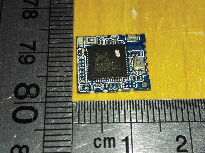
Click to zoom
Application Details
- Equipment Class
- DTS - Digital Transmission System
- Date of Grant
- Dec 22, 2015
- Application Purpose
- Original Equipment
- Date of Application
- Dec 17, 2015
- Equipment Note
- IEEE 802.11b/g/n WLAN BT Combo USB Module
- Frequency Range
- 2412.00000000 - 2462.00000000
- Country
- China
Documents & Files
Document Text
Text extracted from the exhibit documents filed with the FCC. Open a document above to read the original.
Users Manual
FCC Statment This device complies with part 15 of the FCC Rules. Operation is subject to the following two conditions: (1) This device may not cause harmful interference, and (2) this device must accept any interference received, including interference that may cause undesired operation. Note: The manufacturer is not responsible for any radio or TV interference caused by unauthorized modifications to this equipment. such modifications could void the user’s authority to operate this equipment.Any Changes or modifications not expressly approved by the party responsible for compliance could void the user's authority to operate the equipment. This equipment has been tested and found to comply with the limits for a Class B digital device, pursuant to part 15 of FCC Rules. These limits are designed to provide reasonable protection against harmful interference in a residential installation. This equipment generates and can radiate radio frequency energy and, if not installed and used in accordance with the instructions, may cause harmful interference to radio communications. However, there is no guarantee that interference will not occur in a particular installation. If this equipment does cause harmful interference to radio or television reception, which can be determined by turning the equipment off and on, the user is encouraged to try to correct the interference by one or more of the following measures: --Reorient or relocate the receiving antenna. --Increase the separation between the equipment and receiver. --Connect the equipment into an outlet on a circuit different from that to which the receiver is connected. --Consult the dealer or an experienced radio/TV technician for help. RF warning statement The device has been evaluated to meet general RF exposure requirement. The device can be used in Mobile exposure condition with a 20cm distance restriction. The modular can be installed or integrated in mobile or fix devices only. This modular cannot be installed in any portable device, for example, USB dongle like transmitters is forbidden. Co-location statement This device and its antenna(s) must not be co-located or operating in conjunction with any other antenna or transmitter. This modular complies with FCC RF radiation exposure limits set forth for an uncontrolled environment. This transmitter must not be co-located or operating in conjunction with any other antenna or transmitter. If the FCC identification number is not visible when the module is installed inside another device, then the outside of the device into which the module is installed must also display a label referring to the enclosed module. This exterior label can use wording such as the following: “Contains Transmitter Module FCC ID: S8J-R8723BT1 Or Contains FCC ID: S8J-R8723BT1 ” when the module is installed inside another device, the user manual of this device must contain below warning statements; 1. This device complies with Part 15 of the FCC Rules. Operation is subject to the following two conditions: (1) This device may not cause harmful interference. (2) This device must accept any interference received, including interference that may cause undesired operation. 2. Changes or modifications not expressly approved by the party responsible for compliance could void the user's authority to operate the equipment. The devices must be installed and used in strict accordance with the manufacturer's instructions as described in the user documentation that comes with the product. Any company of the host device which install this modular with limit modular approval should perform the test of radiated emission and spurious emission according to FCC part 15C : 15.247 and 15.209 requirement, Only if the test result comply with FCC part 15C : 15.247 and 15.209 requirement,then the host can be sold legally.
Cover Letter(s)
11/23/2015 Equipment Autorisation Division Federal Communications Commission 7435 Oakland Mills Road Columbia, MD 21046 FCC ID: S8J-R8723BT1 Product Name: IEEE 802.11b/g/n WLAN BT Combo USB Module Request for Confidentiality Pursuant to Sections 0.457 and 0.459 of the commissions rules, we hereby request that the following documents be held confidential: Schematics Block diagram Operation description These materials contain trade secrets and proprietary information and are not customarily released to the public. The public disclosure of this information might be harmful to the company and provide unjustified benefits to our competitors. Dated this 11/23/2015 By: Tianle Chen Signature Printed Title: Certification Engineer On behalf of : Shenzhen Bilian Electronic Co., Ltd. Telephone: +86-755-28017217
Cover Letter(s)
Applicant/Grantee Shenzhen Bilian Electronic Co., Ltd. FCC ID: S8J-R8723BT1 Section 15.212 Modular Transmitters Request for Modular Approval Request for Limited Modular Approval Requirements EUT Conditions Comply (Y/N) Single Modular Approval Requirements 1 The radio elements of the modular transmitter must have their own shielding. The physical crystal and tuning capacitors may be located external to the shielded radio elements. Modular has no shielding N 2 The modular transmitter must have buffered modulation/data inputs (if such inputs are provided) to ensure that the module will comply with Part 15 requirements under conditions of excessive data rates or over-modulation. buffered data inputs stage has been integrated in “chip RTL8273BU” Y 3 The modular transmitter must have its own power supply regulation. power supply regulation has been integrated in “chip RTL8273BU” Y 4 The modular transmitter must comply with the antenna and transmission system requirements of Sections 15.203, 15.204(b) and 15.204(c). The antenna must either be permanently attached or employ a “unique” antenna coupler (at all connections between the module and the antenna, including the cable). The “professional installation” provision of Section 15.203 is not applicable to modules but can apply to limited modular approvals under paragraph (b) of this section. The requirements of antenna connector and spurious emission have been fulfilled. Please refer to the Test Report. Y 5 The modular transmitter must be tested in a stand-alone configuration, i.e., the module must not be inside another device during testing for compliance with Part 15 requirements. Unless the transmitter module will be battery powered, it must comply with the AC line conducted requirements found in Section 15.207. AC or DC power lines and data input/output lines connected to the module must not contain ferrites, unless they will be marketed with the module (see Section 15.27(a)). The length of these lines shall be the length typical of actual use or, if that length is unknown, at least 10 centimeters to insure that there is no coupling between the case of the module and supporting Please refer to Setup Photo for the stand- alone test configuration. Y Device is equipped with PCB antenna. Distance between modular and all AEs are bigger than 10cm ˈrefer to setup photo. Device is equipped with external antenna which have reversed polarity non standard antenna port Distance between modular and all AEs are shorter than 10cm refer to setup photo. N equipment. Any accessories, peripherals, or support equipment connected to the module during testing shall be unmodified and commercially available (see Section 15.31(i)). 6 The modular transmitter must be equipped with either a permanently affixed label or must be capable of electronically displaying its FCC identification number. (A) If using a permanently affixed label, the modular transmitter must be labeled with its own FCC identification number, and, if the FCC identification number is not visible when the module is installed inside another device, then the outside of the device into which the module is installed must also display a label referring to the enclosed module. This exterior label can use wording such as the following: “Contains Transmitter Module FCC ID: XYZMODEL1” or “Contains FCC ID: XYZMODEL1.” Any similar wording that expresses the same meaning may be used. The Grantee may either provide such a label, an example of which must be included in the application for equipment authorization, or, must provide adequate instructions along with the module which explain this requirement. In the latter case, a copy of these instructions must be included in the application for equipment authorization. (B) If the modular transmitter uses an electronic display of the FCC identification number, the information must be readily accessible and visible on the modular transmitter or on the device in which it is installed. If the module is installed inside another device, then the outside of the device into which the module is installed must display a label referring to the enclosed module. This exterior label can use wording such as the following: “Contains FCC certified transmitter module(s).” Any similar wording that expresses the same meaning may be used. The user manual must include instructions on how to access the electronic display. A copy of these instructions must be included in the application for equipment authorization. User manual contains instructions to label the host device containing this module as follows: Contains FCC ID: S8J-R8723BT1 Y 7 The modular transmitter must comply with any specific rules or operating requirements that ordinarily apply to a complete transmitter and the manufacturer must provide adequate instructions along with the module to explain any such requirements. A copy of these instructions must be included in the application for equipment authorization. Specific installation instructions are provided in the user manual for this module Y The modular has a permanent fixed label, and below statement was listed in the User Manual;The host device must be labeled to display the FCC ID of the module “Contains FCC ID: S8J- R8723BT1” The module comply with all specific rules applicable to the transmitter including all the conditions provided in the integration instructions by the grantee, Refer to test report and user manual . Transmitter meets MPE calculation of 47 CFR 1.1307 . Refer to MPE Reports and Refer to modular installation manual
External Photos
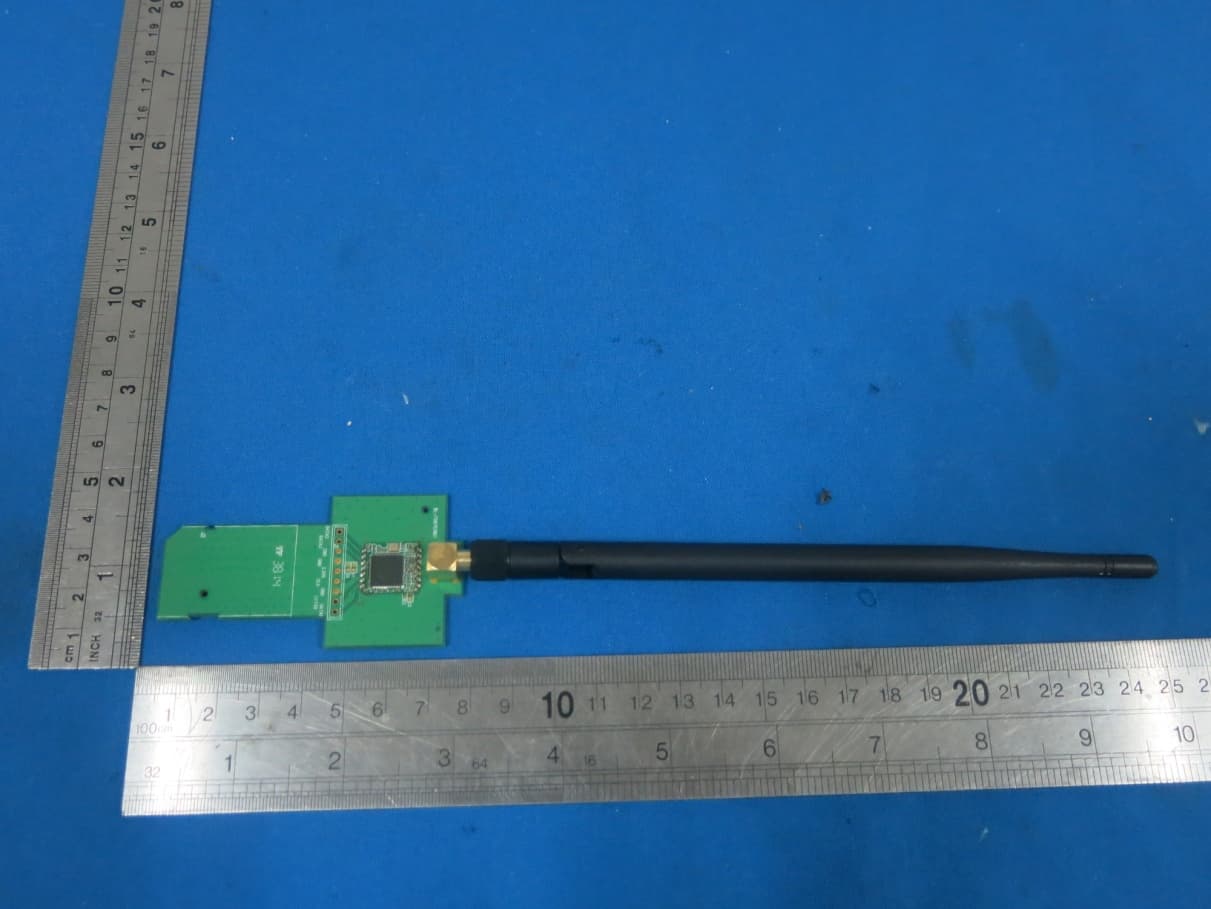
Photos of EUT Model Name: BL-R8723BT1 Reversed polarity non standard antenna port
ID Label/Location Info
Model Name:BL‐R8723BT1 Label in the user manual: Label on EUT
Internal Photos
Photos of EUT Model Name: BL-R8723BT1
RF Exposure Info
MPE Calculation Method E (V/m) = (30*P*G) 0.5 /d Power Density: Pd (W/m2) = E 2 /377 E = Electric Field (V/m) P = Peak RF output Power (W) G = EUT Antenna numeric gain (numeric) d = Separation distance between radiator and human body (m) The formula can be changed to Pd = (30*P*G) / (377*d 2 ) From the peak EUT RF output power, the minimum mobile separation distance, d=0.2m, as well as the gain of the used antenna, the RF power density can be obtained. Calculated Result and Limit(WORSE CASE IS AS BELOW) Antenna Gain (Numeric) Peak Output Power (mW) Power Density (S) (mW/cm2) Limit of Power Density (S) (mW/cm2) Test Result 3.16 (5.0dBi) 17.06 (12.32dBm) 0.011 1 Compiles
Test Report
Shenzhen GTI Technology Co., Ltd. 1F,2 Block, Jiaquan Building, Guanlan High-tech Park Baoan District, Shenzhen, Guangdong, China. Tel: +86-755-27559792 Fax: +86-755-86116468 Report No.: GTI20150556F-1 Page 1 of 62 TEST REPORT Product Name ........................... : IEEE 802.11b/g/n WLAN BT Combo USB Module Trademark ................................. : LB-LINK Model/Type reference ............... : BL-R8723BT1 Listed Model(s) ......................... : / FCC ID ........................................ : S8J-R8723BT1 Test Standards .......................... : FCC Part 15.247: Operation within the bands 902-928 MHz, 2400-2483.5 MHz and 5725-5850 MHz Applicant ................................... : Shenzhen Bilian Electronic Co., Ltd. Address of applicant ................ : Building B1, Zhongxing Industrial Zone, Juling, Jutang Community, Guanlan street, Bao'an, Shenzhen, China Date of Receipt ......................... : Oct. 12, 2015 Date of Test Date ....................... : Oct. 12, 2015 - Nov. 03, 2015 Data of issue. ............................ : Nov. 03, 2015 Test result Pass * * In the configuration tested, the EUT complied with the standards specified above Page 2 of 62 Report No.: GTI20150556F-1 Shenzhen General Testing & Inspection Technology Co., Ltd. 1F, 2 Block, Jiaquan Building, Guanlan High-tech Park Baoan District, Shenzhen, Guangdong, China Tel.: (86)755-27588991 Fax: (86)755-86116468 Http://www.sz-ctc.com.cn GENERAL DESCRIPTION OF EUT Equipment: IEEE 802.11b/g/n WLAN BT Combo USB Module Model Name: BL-R8723BT1 Manufacturer: Shenzhen Bilian Electronic Co., Ltd. Manufacturer Address: Building B1, Zhongxing Industrial Zone, Juling, Jutang Community, Guanlan street, Bao'an, Shenzhen, China Power Rating: DC 5.0V form PC Compiled By: (Thomas Morgan) Reviewed By: (Tony Wang) Approved By: (Walter Chen) This test report consists of 62 pages in total. It may be duplicated completely for legal use with the approval of the applicant. It should not be reproduced except in full, without the written approval of our laboratory. The client should not use it to claim product endorsement by GTI. The test results in the report only apply to the tested sample. The test report shall be invalid without all the signatures of compiler, reviewer and approver. Any objections must be raised to GTI within 15 days since the date when the report is received. It will not be taken into consideration beyond this limit. Page 3 of 62 Report No.: GTI20150556F-1 Shenzhen General Testing & Inspection Technology Co., Ltd. 1F, 2 Block, Jiaquan Building, Guanlan High-tech Park Baoan District, Shenzhen, Guangdong, China Tel.: (86)755-27588991 Fax: (86)755-86116468 Http://www.sz-ctc.com.cn Table of Contents Page 1. SUMMARY ............................................................................................................................................................ 4 1.1. TEST STANDARDS .......................................................................................................................................................... 4 1.2. TEST DESCRIPTION ........................................................................................................................................................ 4 1.3. TEST FACILITY .............................................................................................................................................................. 5 1.4. MEASUREMENT UNCERTAINTY ........................................................................................................................................ 5 2. GENERAL INFORMATION ....................................................................................................................................... 6 2.1. ENVIRONMENTAL CONDITIONS ........................................................................................................................................ 6 2.2. GENERAL DESCRIPTION OF EUT ...................................................................................................................................... 6 2.3. DESCRIPTION OF TEST MODES ........................................................................................................................................ 7 2.1. MEASUREMENT INSTRUMENTS LIST ................................................................................................................................. 9 3. TEST CONDITIONS AND RESULTS ......................................................................................................................... 10 3.1. CONDUCTED EMISSION (AC MAIN) ............................................................................................................................... 10 3.2. RADIATED EMISSION ................................................................................................................................................... 15 3.3. MAXIMUM CONDUCTED OUTPUT POWER ....................................................................................................................... 26 3.4. POWER SPECTRAL DENSITY .......................................................................................................................................... 28 3.5. 6DB BANDWIDTH ....................................................................................................................................................... 32 3.6. BAND EDGE COMPLIANCE OF RF EMISSION ..................................................................................................................... 36 3.7. SPURIOUS RF CONDUCTED EMISSION ............................................................................................................................. 43 3.8. ANTENNA REQUIREMENT ............................................................................................................................................. 59 4. EUT TEST PHOTO ..........................................…
Text truncated - open the document above for the full version.
Test Setup Photos
Test Setup Photos Model Name: BL-R8723BT1 Radiated Emission (30MHz-1GHz) Radiated Emission (1GHz-25GHz) Conducted Emission
Contact Information
Applicant
Tianle Chen(Certification Engineer)
Test Firm
Shenzhen GTI Technology Co., Ltd.Walter Chen
Technical Specifications
| # | Rule Parts | Frequency Range | Power Output |
|---|---|---|---|
| 2 | 15C | 2.41 GHz - 2.46 GHz | 17.06 mW |
Other Applications from Shenzhen Bilian Electronic Co., Ltd.
S8J-R8782MS1
Oct 24, 2015150Mbps Wireless N SDIO Module
Equipment Class
DTS - Digital Transmission System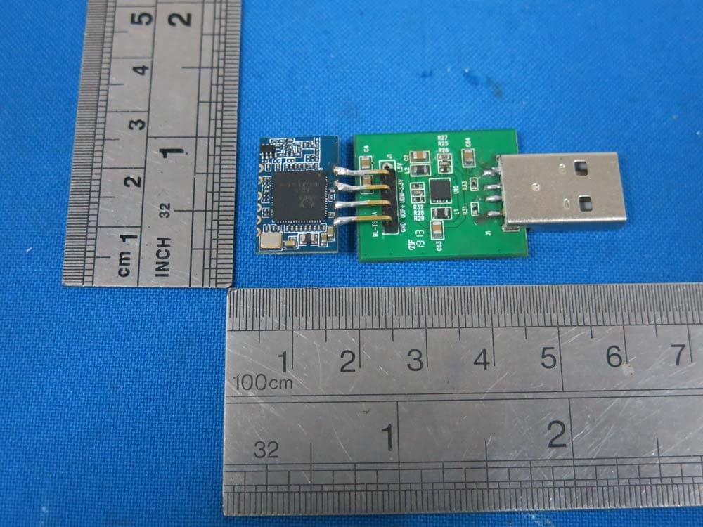
S8J-R8723RB1
Aug 31, 2015Bluetooth 150Mbps Wireless N USB Module
Equipment Class
DSS - Part 15 Spread Spectrum Transmitter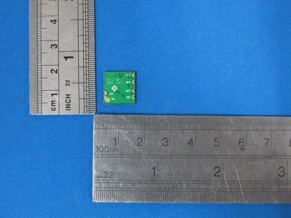
S8J-R8188EU1
Aug 18, 2015150Mbps Wireless N SDIO Module
Equipment Class
DTS - Digital Transmission System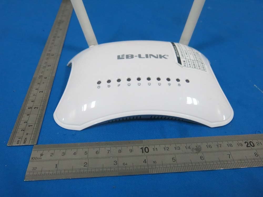
S8J-WMR8300
Apr 25, 2015300Mbps Wireless N ADSL2 Modem Router
Equipment Class
DTS - Digital Transmission System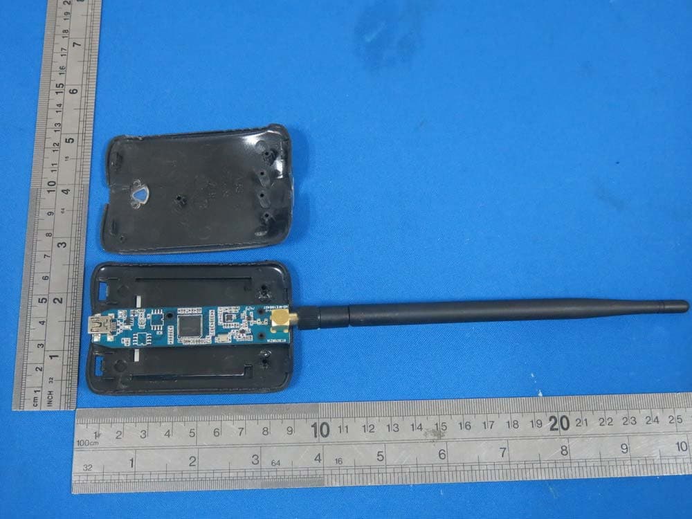
S8J-WN150AH
Apr 23, 2015150Mbps High Gain Wireless N USB Adapter
Equipment Class
DTS - Digital Transmission System