S8OMDET3380Alert Metalguard Metal Detector
Alert Metalguard ApS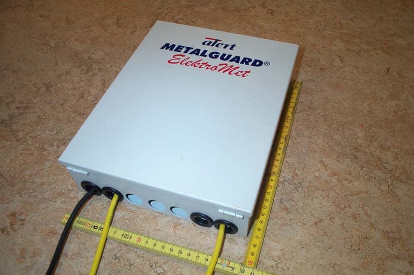
Click to zoom
Application Details
- Equipment Class
- FAP - Part 15 Anti-Pilferage Device
- Date of Grant
- Jul 08, 2005
- Application Purpose
- Original Equipment
- Date of Application
- Jul 08, 2005
- Equipment Note
- Alert Metalguard Metal Detector
- Frequency Range
- 0.07800000 - 0.08990000
- Company
- Alert Metalguard ApS
- Country
- Denmark
Documents & Files
Document Text
Text extracted from the exhibit documents filed with the FCC. Open a document above to read the original.
Users Manual
Federal Communications Commission and Industry Canada Statement WARNING! This device complies with part 15 of the FCC Rules and RSS-210 of the Canadian Rules. Operation is subject to the following two conditions: (1) this device may not cause harmful interference, and (2) this device must accept any interference received, including interference that may cause undesired operation of the device. Note: This equipment has been tested and found to comply with the limits for a Class B digital device, pursuant to Part 15 of the FCC Rules. These limits are designed to provide reasonable protection against harmful interference in a residential installation. This equipment generates, uses and can radiate radio frequency energy and, if not installed and used in accordance with the instructions, may course harmful interference to radio communications. However, there is no guarantee that interference will not occur in a particular installation. If this equipment does cause harmful interference to radio or television reception, which can be determined by tuning the equipment off and on, the user is encouraged to try to correct the interference by one of the following measures: --Reorient or relocate the receiving antenna. --Increase the separation between the equipment and receiver. --Connect the equipment into an outlet on a circuit different from that to which the receiver is connected --Consult the dealer or an experienced radio/TV technician for help. Changes or modifications not expressly approved by the party responsible for compliance could void the user’s authority to operate the equipment This User Manual is valid for the following products: FCC ID: S8OMDET3320 and S8OMDET3380 - IC ID: 5849A-MDET3320 and IC ID: 5849A-MDET3380 User’s Manual Article number: 90310901 10
External Photos
External photo FCC ID: S8OMDET3380 IC ID: 5849A-MDET3380
ID Label/Location Info
FCC ID: S8OMDET3380 IC ID: 5849A-MDET3380 Label for Alert Metalguard ElectroMet 3.3-1 Alert METALGUARD ApS CVR: 24 22 77 31 Carl Jacobsens Vej 16, opg. 11, 3. sal VAT nr. 21 87 55 89 DK-2500 Valby Danske Bank: 33613116299151 Denmark mailto:[email protected] Phone: +45 36 46 71 71 Fax: +45 36 46 71 74 http://www.alertmetalguard.com/ GSM: +45 40 42 56 10
ID Label/Location Info
Label Position FCC ID: S8OMDET3380 IC ID: 5849A-MDET3380 Label Position for Alert Metalguard ElectroMet 3.3-1 Alert METALGUARD ApS CVR: 24 22 77 31 Carl Jacobsens Vej 16, opg. 11, 3. sal VAT nr. 21 87 55 89 DK-2500 Valby Danske Bank: 33613116299151 Denmark mailto:[email protected] Phone: +45 36 46 71 71 Fax: +45 36 46 71 74 http://www.alertmetalguard.com/ GSM: +45 40 42 56 10
Operational Description
Alert METALGUARD ApS CVR: 24 22 77 31 Carl Jacobsens Vej 16, opg. 11, 3. sal VAT nr. 21 87 55 89 DK-2500 Valby Danske Bank: 33613116299151 Denmark mailto:[email protected] Phone: +45 36 46 71 71 Fax: +45 36 46 71 74 http://www.alertmetalguard.com/ GSM: +45 40 42 56 10 June 29, 2005 Re: Operational description for Alert Metalguard ElectroMet 3.3-1 FCC ID: S8OMDET3380 IC ID: 5849A-MDET3380 This system is a metal detection system used in retail shops detecting foil-lined bags known as “Booster Bags” 3 antennas (1-2-3) are installed next to each other with a distance of 160cm in between. This represents 2 gates. These gates can be installed at the entrance, at the exits or inside the shop. Each antenna consist worst case of a coil of one winding with the size of 150cm x 30cm. All antenna coils are positioned in parallel. Antenna 1 is a transmitter antenna and is connected to TX1 Antenna 2 is a receiver antenna and is connected to RX1 Antenna 3 is a transmitter antenna and is connected to TX2 When a booster bag, (a foil-lined bag), is passing through the gates, the results is that the receiving signal is reduced a little bit. This is detected in the Metal adj. module and the alarm module is activated, and two pairs of dry relay contacts closes. When a trolley is passing through the gates, the results is that the receiving signal is reduced a lot. This is detected in the Trolley adj. module and the alarm is blocked. When people are bumping into the antennas, the results is that the receiving signal vary a little bit. This is detected in the Move adj. module and the alarm is blocked. An additional electronic box can be connected as a slave box and is synchronized by TX sync signals. A trolley passing through the slave gates can create false alarms in the master system. The trolley sync signal from the slave box then blocks the alarm in the master electronic box.
Test Report
20dan-uk-i DELTA Danish Electronics, Light & Acoustics Venlighedsvej 4 2970 Hørsholm Denmark Tel. (+45) 72 19 40 00 Fax (+45) 72 19 40 01 www.delta.dk This report is issued under the rules of DANAK (Danish Accreditation). Further information about DANAK can be found at www.danak.dk. The report must not be reproduced, except in full, without the written approval of DELTA. Test Report DANAK Reg. no. 19 We help ideas meet the real world Emission tests to FCC and IC requirements of ElectroMet Control Unit Performed for Alert Metalguard ApS DANAK-197951 Rev. A Project no.: A502954-2 Page 1 of 12 5 annexes 29 June 2005 DANAK-197951 Rev. A DELTA-A502954-2 Page 2 of 12 VS/AED Title Emission tests to FCC and IC requirements of ElectroMet Control Unit Test object ElectroMet Control Unit ID FCC ID:S8OMDET3380 IC: 5849A-MDET3380 Report no. DANAK-197951 Rev. A Project no. A502954-2 Test period 29 to 31 March 2005 Client Alert Metalguard ApS Carl Jacobsens Vej 16, Opg. 11, 3. sal 2500 Valby Denmark Tel.: +45 3646 7171 Contact person Mr. Verner Falkenberg Manufacturer Alert Metalguard ApS Specifications FCC:47 CFR Part 15, Subpart C - Intentional Radiators IC: RSS-210, Section 6.2 Non-Momentarily Operated De- vices Results The equipment under test is in compliance with the re- quirements. Test personnel Karsten Kruse Jensen Bjørn Larsen Vagn Sylvest Date 29 June 2005 Responsible Vagn Sylvest Project Manager - EMC DELTA This revision A replaces previously issued report DANAK-197951 dated 26 May 2005. The revision has been made due to the following corrections: Page 2 FCC ID: S8OMEDET3380 has been changed to S8OMDET3380 IC: 5849A-MEDET3380 has been changed to 5849A-MDET3380. DANAK-197951 Rev. A DELTA-A502954-2 Page 3 of 12 VS/AED Table of contents Page 1. Summaries 4 1.1 Technical report summary 4 1.2 Summary of tests 5 2. Test objects 6 2.1 Test object - Control unit - ElectroMet 6 2.2 Test object - Antenna Test loop 1 6 2.3 Test object - Antenna Test loop 3 6 2.4 Test object - Antenna Test loop 4 6 3. General test conditions 7 3.1 Test set-up 7 4. Test and results 8 4.1 Conducted emission, AC mains 8 4.2 General field strength limits below 30 MHz 9 4.3 General field strength limits above 30 MHz 10 4.4 Occupied bandwidth 11 4.5 Peak output field strength 11 Annex 1 List of instruments (1 page) Annex 2 Photos (3 pages) Annex 3 Test record sheets regarding conducted emission (2 pages) Annex 4 Test record sheets regarding radiated emission (2 pages) Annex 5 Exploratory plots (3 pages) DANAK-197951 Rev. A DELTA-A502954-2 Page 4 of 12 VS/AED 1. Summaries 1.1 Technical report summary The tests reported in this document have been performed to demonstrate compliance with the requirements of FCC Part 15, Section 15.207 "Conducted limits" and FCC Part 15, Section 15.209 "Radiated emission limits, general requirements". Furthermore, the tests reported in this document have been performed to demonstrate compliance with the requirements of IC requirement RSS-210, section 6.6 Transmitter AC Wireline Conducted Emissions and section 6.2 Non-Momentarily Operated Devices. The receiver can only tune to frequencies below 30 MHz and is therefore exempt from complying with technical requirements. This report contains measurement data from tests performed at DELTA, Hørsholm, Denmark, a DANAK accredited test laboratory with reference number 19. The laboratory is listed by FCC under the registration number 90529. The laboratory is listed by Industry Canada under the reference IC 4187-5. 1.1.1 Applicable test methods The methods and procedures have been applied as specified in: • ANSI C63.4:2003 Methods of Measurement of Radio-Noise Emissions from Low- Voltage Electrical and Electronic Equipment in the range of 9 kHz to 40 GHz. • RSS-212 Test Facilities and Test Methods for Radio Equipment DANAK-197951 Rev. A DELTA-A502954-2 Page 5 of 12 VS/AED 1.2 Summary of tests The results of the emission tests can be summarised as follows: Tests of Intentional Radiator Key references to requirement Common FCC and IC status Conducted emission, AC mains FCC 15.207 IC RSS-210, 6.6 Passed Radiated electromagnetic field emission FCC15.209 IC RSS-210, 6.2.1 Passed Emission in restricted bands FCC15.205 IC RSS-210, 6.3 Passed Abbreviations Passed : The requirements are met. Failed : The requirements are not met. Not done : No test was performed. N/A : Not applicable. Not relevant : The test was not relevant for the test object. The test results relate only to the objects tested. DANAK-197951 Rev. A DELTA-A502954-2 Page 6 of 12 VS/AED 2. Test objects 2.1 Test object - Control unit - ElectroMet Category Inductive RF system, 78-89,9 kHz Manufacturer Alert Metalguard ApS Model / type ElectroMet Article no. 9031095110 Serial no.(PCB) 050208 Supply voltage 120 VAC Operational mode Normal 2.2 Test object - Antenna Test loop 1 Manufacturer Alert Metalguard ApS Model / type 49 x 171 cm single loop (0.83 m square) This antenna was used as receiver antenna. 2.3 Test object - Antenna Test loop 3 Manufacturer Alert Metalguard ApS Model / type 15 x 150 cm double loop (0.45 m square) 2.4 Test object - Antenna Test loop 4 Manufacturer Alert Metalguard ApS Model / type 15 x 150 cm double loop (0.45 m square) DANAK-197951 Rev. A DELTA-A502954-2 Page 7 of 12 VS/AED 3. General test conditions 3.1 Test set-up The system is transmitting a CW signal. When a large metal part, like for example a bag internally covered with alu-foil to prevent detection of electronic security marks on goods, then the special signal pattern generated is extracted from the receive signal. An alarm can be generated. The transmitting frequency is determined by x-tals for frequencies in the interval 78 to 86.4 kHz. Detector 1Detector 2Detector 3 TX 1RXTX 2 Mains Aux TX 1 RX TX 2 Å----------- System under test -------------------------------------------------Æ The system can have one or two transmit antennas. During test two transmit antennas were used. A receiver antenna was also attached. The …
Text truncated - open the document above for the full version.
Test Setup Photos
20fotorap-uk-k DELTA Danish Electronics, Light & Acoustics Venlighedsvej 4 2970 Hørsholm Denmark Tel. (+45) 72 19 40 00 Fax (+45) 72 19 40 01 www.delta.dk Test setup photos We help ideas meet the real world Emission tests to FCC and IC requirements of ElectroMet Control Unit Performed for Alert Metalguard ApS Page 1 of 4 This exhibit is an extract of DELTA Test Report A502954-2 DANAK-197951 Rev. A 29 June 2005 containing only the photos of the test setups DANAK-197951 Rev. A DELTA-A502954-2 Page 2 of 4 VS/BLJ Photo 1 Radiated emission 30-1000 MHz. Photo 2 Radiated emission 30-1000 MHz. DANAK-197951 Rev. A DELTA-A502954-2 Page 3 of 4 VS/BLJ Photo 3 Conducted emission, 0.15 - 30 MHz. Photo 4 Radiated emission. 30 m OATS. DANAK-197951 Rev. A DELTA-A502954-2 Page 4 of 4 VS/BLJ Photo 5 Radiated emission. 30 m OATS. Photo 6 Test set-up during exploratory measurements
Contact Information
Applicant
Nimesh Shah(R&D Director of Operations)
Test Firm
DELTA Electronic TestingJorgen Christensen
Technical Specifications
| # | Rule Parts | Frequency Range | Power Output |
|---|---|---|---|
| 1 | 15C | 0.078 MHz - 0.0899 MHz | - |
Other Applications from Alert Metalguard ApS
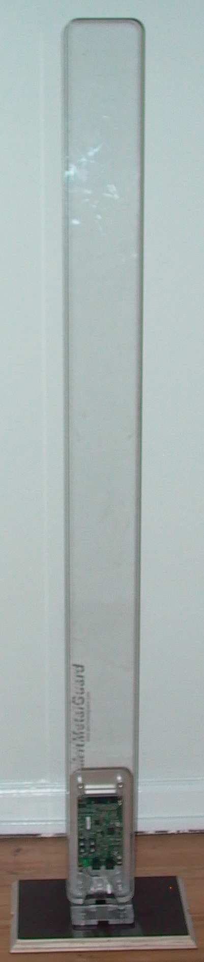
S8OHYPER1730
Aug 07, 2013Alert HyperGuard v2.0
Equipment Class
FAP - Part 15 Anti-Pilferage Device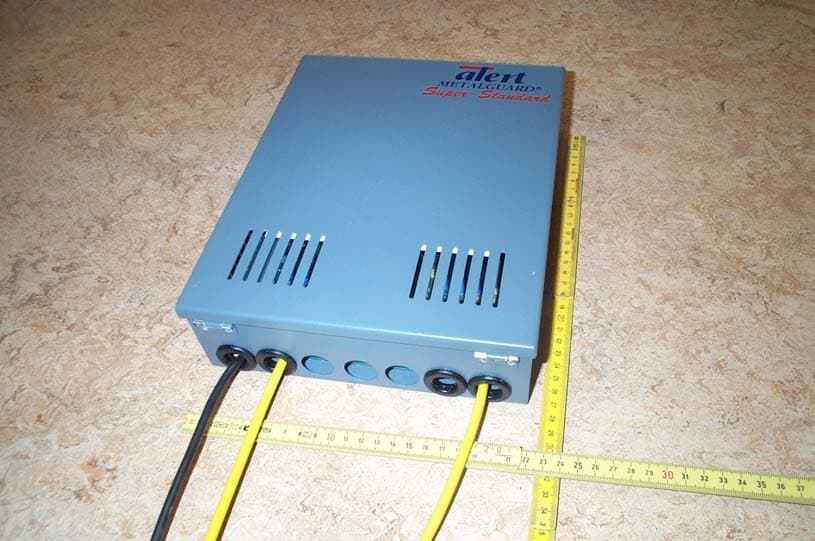
S8OMDET3320
Jul 08, 2005Alert Metalguard Metal Detector
Equipment Class
FAP - Part 15 Anti-Pilferage Device