S92WRS368TXV1Music Sphere - Wireless Remote Speaker
IDT Sonicvision Limited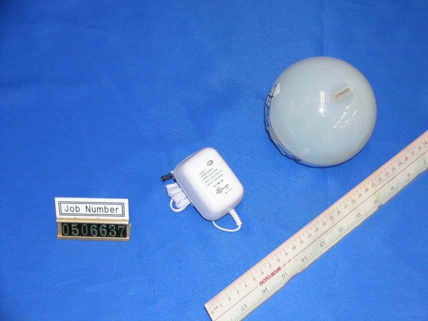
Click to zoom
Application Details
- Equipment Class
- DSS - Part 15 Spread Spectrum Transmitter
- Date of Grant
- Jul 07, 2005
- Application Purpose
- Original Equipment
- Date of Application
- Jul 07, 2005
- Equipment Note
- Music Sphere - Wireless Remote Speaker
- Frequency Range
- 2403.00000000 - 2479.00000000
- Company
- IDT Sonicvision Limited
- Country
- Hong Kong
Documents & Files
Document Text
Text extracted from the exhibit documents filed with the FCC. Open a document above to read the original.
Users Manual
Music Sphere Wireless Remote Speaker System Model: WRS368 User Manual WRS368 Eng Cover R155/10/05, 11:47 AM1 EN 1 IMPORTANT SAFETY INSTRUCTIONS The Music Sphere Wireless Remote Speaker System is designed to give you years of service if handled properly. Ensure that you heed all warnings to minimize product malfunction and reduce the chances of incurring personal injury. Before using the unit, observe the following guidelines to ensure proper care and maintenance. The lightning flash with arrowhead symbol within an equilateral triangle, is intended to alert the user to the presence of uninsulated "dangerous voltage" within the products enclosure that may be of sufficient magnitude to constitute a risk of electric shock to persons. The exclamation point within an equilateral triangle is intended to alert the user to the presence of important operating and maintenance (servicing) instructions in the literature accom- panying the appliance. To prevent fire or shock hazard, do not use this plug with an extension cord, receptacle or other outlet unless the blades can be fully inserted to prevent blade exposure. READ INSTRUCTIONS All safety and operating instructions should be read and followed before operating the product and should be retained for future reference. All warnings on the product and in the operating instructions should be adhered to. CLEANING Unplug all adaptors and cables from the wall outlet before cleaning. Do not use liquid cleaners or aerosol cleaners. Use a damp cloth for cleaning. ATTACHMENTS Do not use attachments not recommended by Oregon Scientific as they may cause hazards. WATER AND MOISTURE Do not use this product near water – for example, near a bathtub, washbowl, kitchen sink or laundry tub; in a wet basement; or swimming pool; and the like. SEE MARKING ON BOTTOM / BACK OF PRODUCT ACCESSORIES Take care when placing the product on an unstable cart, stand, tripod, bracket or table. Quick stops, excessive force and uneven surfaces may cause the system to overturn and fall, causing serious injury to a child or adult, and serious damage to the product. Use only with a cart, stand, tripod, bracket or table recommended by Oregon Scientific, or sold with the product. VENTILATION Slots and openings in the product are provided for ventilation and to ensure reliable operation of the product and to protect it from overheating. These openings should never be blocked or covered by placing the product on a bed, sofa, rug or other similar surface. The product should not be placed in a built-in installation such as a bookcase or rack unless proper ventilation is provided or Oregon Scientific’s instructions have been adhered to. HEAT The product should be situated away from heat sources such as radiators, heat registers, stoves, or other products (including amplifiers) that produce heat. POWER SOURCES The system should be operated only from the type of power source indicated on the marking label. If you are not sure of the type of power supply to your home, consult your Oregon Scientific dealer or local power company. For products intended to operate battery power, or other sources, refer to the operating instructions. GROUNDING OR POLARIZATION The product may be equipped with a polarized alternating-current line plug (a plug having one blade wider than the other). This plug will fit into the power outlet only one way. The product may be equipped with a 3-blade grounding-type plug, a plug having a third (grounding) pin. This plug should only fit into a grounding- type power outlet. Both plugs are safety features of the product. If either plug is unable to fully insert into its respective outlet, try reversing the plug. If the plug should still fail to insert, contact your electrician to replace the obsolete outlet. Do not defeat the safety purpose of the polarized or grounding-type plug. POWER-CORD PROTECTION Power supply cords should be routed so that they are not likely to be walked on or pinched by items placed upon or against them, paying particular attention to cords at plugs, convenience receptacles, and the point where they exit from the product. WRS368 Eng R155/10/05, 12:53 PM1 EN 2 PROTECTIVE ATTACHMENT PLUG The product is equipped with an attachment plug having overload protection. This is a safety feature. See user manual for replacement or resetting of protective device. If replacement of the plug is required, be sure the service technician has used a replacement plug specified by Oregon Scientific that has the same overload protection as the original plug. OUTDOOR ANTENNA GROUNDING If an outside antenna or cable system is connected to the product, be sure the antenna or cable system is grounded so as to provide some protection against voltage surges and built-up static charges. Article 810 of the National Electrical Code, ANSI / NFPA 70, provides information with regard to proper grounding of the mast and supporting structure, grounding of the lead- in wire to an antenna discharge unit, size of grounding conductors, location of antenna-discharge unit, connection to grounding electrodes, and requirements for the grounding electrode. LIGHTNING For added protection for the system during a lightning storm, or when it is left unattended and unused for long periods of time, unplug it from the wall outlet and disconnect any cables. This will prevent damage to the system due to lightning and power-line surges. POWER LINES An outside antenna system should not be located near any overhead power lines or other electric light or power circuits, or when it can fall into such power lines or circuits. When installing an outside antenna system, extreme care should be taken to keep from touching such power lines or circuits as contact with them might be fatal. OVERLOADING Do not overload wall outlets, extension cords, or integral convenience receptacles as this can result in a risk of fire or electric shock. OBJECT AND LIQUID ENTRY Never push objects of any kind into this product throu…
Text truncated - open the document above for the full version.
External Photos
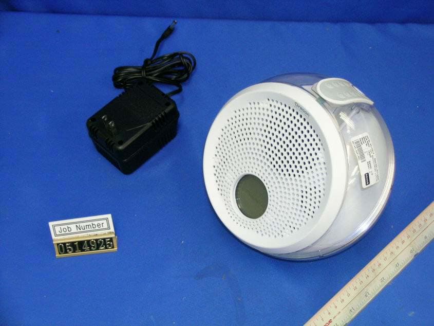
Test Setup FCC ID : S92WRS368TXV1 External Photo - Front External Photo - Rear Job Number 0505854 Job Number 0505854
ID Label/Location Info
DCAdaptorV300mA9 WRS368 WRS368 T his device complies with P a rt 15 of the F C C R ules . O pera tion is s ubject to the following two conditions : (1) T his device ma y not ca us e ha rmful interference, a nd (2) this device mus t a ccept a ny interference received, including interference tha t ma y ca us e undes ired opera tion. T his device complies with P a rt 15 of the F C C R ules . O pera tion is s ubject to the following two conditions : (1) T his device ma y not ca us e ha rmful interference, a nd (2) this device mus t a ccept a ny interference received, including interference tha t ma y ca us e undes ired opera tion. DCAdaptor9V1500mA DC9V6x1.5V(LR14,AM2, C Size) FCC ID: S92WRS368RXV1 FCC ID: S92WRS368TXV1 42.8mm 26.8mm 48.7mm 26 . 6 m m
Internal Photos
Test Setup FCC ID : S92WRS368TXV1 Internal Photo - 1 Internal Photo - 2 Test Setup FCC ID : S92WRS368TXV1 Internal Photo - 3 Internal Photo - 4 Test Setup FCC ID : S92WRS368TXV1 Internal Photo - 5 Internal Photo - 6 Test Setup FCC ID : S92WRS368TXV1 Internal Photo - 7 Internal Photo - 8 Test Setup FCC ID : S92WRS368TXV1 Internal Photo - 9 Internal Photo - 10 Test Setup FCC ID : S92WRS368TXV1 Internal Photo - 11 Internal Photo - 12 Test Setup FCC ID : S92WRS368TXV1 Internal Photo - 13 Internal Photo - 14 Test Setup FCC ID : S92WRS368TXV1 Internal Photo - 15 Internal Photo - 16 Test Setup FCC ID : S92WRS368TXV1 Internal Photo - 17 Internal Photo - 18
Test Report
• The test results reported in this test report shall refer only to the sample actually tested and shall not refer or be deemed to refer to bulk from which such a sample may be said to have been obtained. • This report shall not be reproduced except in full without prior authorization from Intertek Testing Services Hong Kong Limited. • For Terms And Conditions of the services, it can be provided upon request. • The evaluation data of the report will be kept for 3 years from the date of issuance. Intertek Testing Services Hong Kong Ltd. 2/F., Garment Centre, 576 Castle Peak Road, Kowloon, Hong Kong. Tel: (852) 2173 8888 Fax: (852) 2741 1693 Website: www.hk.intertek-etlsemko.com IDT Sonicvision Limited Application For Certification Music Sphere - Wireless Remote Speaker (Transmitter Unit) (FCC ID: S92WRS368TXV1) 0505854 DL/ Sandy Lee May 25, 2005 INTERTEK TESTING SERVICES FCC ID: S92WRS368TXV1 i LIST OF EXHIBITS INTRODUCTION EXHIBIT 1: Summary of Tests EXHIBIT 2: General Description EXHIBIT 3: System Test Configuration EXHIBIT 4: Measurement Results EXHIBIT 5: Equipment Photographs EXHIBIT 6: Product Labelling EXHIBIT 7: Technical Specifications EXHIBIT 8: Instruction Manual EXHIBIT 9: Confidentiality Request INTERTEK TESTING SERVICES FCC ID: S92WRS368TXV1 ii MEASUREMENT/TECHNICAL REPORT IDT Sonicvision Limited - MODEL: Oregon Scientific WRS368 FCC ID: S92WRS368TXV1 This report concerns (check one) Original Grant X Class II Change Equipment Type: DSS-Part 15 Spread Spectrum Transmitter Deferred grant requested per 47 CFR 0.457(d)(1)(ii)? Yes No X If yes, defer until : dae Company Name agrees to notify the Commission by: date of the intended date of announcement of the product so that the grant can be issued on that date. Transition Rules Request per 15.37? Yes No X If no, assumed Part 15, Subpart C for intentional radiator - the new 47 CFR [12- 08-03 Edition] provision. Report prepared by: Derek Leung Intertek Testing Services 2/F., Garment Centre, 576 Castle Peak Road, Kowloon, Hong Kong. Phone: 852-2173-8539 Fax: 852-2371-0521 INTERTEK TESTING SERVICES FCC ID: S92WRS368TXV1 iii Table of Contents 1.0 Summary of test results .......................................................................................................... 2 2.0 General Description ...........................................................................................................4 2.1 Product Description ..........................................................................................................4 2.2 Related Submittal(s) Grants ..............................................................................................5 2.3 Test Methodology .............................................................................................................5 2.4 Test Facility ......................................................................................................................5 3.0 System Test Configuration ................................................................................................7 3.1 Justification .......................................................................................................................7 3.2 EUT Exercising Software ..................................................................................................7 3.3 Support Equipment List and Description............................................................................8 3.4 Measurement Uncertainty....................................................................................................... 9 3.5 Equipment Modification .....................................................................................................9 4.0 Measurement Results ......................................................................................................11 4.1 Maximum Conducted Output Power at Antenna Terminals...........................................11 4.2 Hopping Channel 20 dB RF Bandwidth ........................................................................12 4.3 Minimum Number of Hopping Frequencies ...................................................................... 13 4.4 Minimum Hopping Channel Carrier Frequency Separation ............................................. 14 4.5 Average Channel Occupancy Time..............................................................................15 4.6 Out of Band Radiated Emissions ...................................................................................... 16 4.7 Out of Band Radiated Emissions..................................................................................17 4.8 Transmitter Radiated Emissions in Restricted Bands ...................................................... 18 4.9 Field Strength Calculation ............................................................................................19 4.10 Radiated Emission Configuration Photograph.................................................................. 20 4.11 Radiated Emission Data...............................................................................................21 4.12 AC Line Conducted Emission.......................................................................................25 4.13 Line Conducted Configuration Photograph ...................................................................26 4.14 Line Conducted Emission Configuration Data...............................................................27 4.15 Radiated Emissions from Digital Section of Transceiver (Transmitter) ........................... 28 4.16 Transmitter Duty Cycle Calculation and Measurements .............................................30 5.0 Equipment Photographs .................................................................................................32 6.0 Product Labelling .............................................................................................................34 7.0 Technical Specifications ...................................…
Text truncated - open the document above for the full version.
Test Report
Report No.:0505854 Ctrl No.:N/A PAGE 1 Tested By:Hong, Report No.:0505854 Scan Settings (1 Range) |--------- Frequencies -----------||----------- Receiver Settings ------------| Start Stop Step IF BW Detector M-Time Atten Preamp OpRge 150k 30M 5k 10k PK+AV 10ms AUTO LN OFF 60dB Final Measurement: x QP / + AV Meas Time: 1 s Subranges: 16 Acc Margin: 20dB Transducer No. Start Stop Name 21 9k 30M EW0698 0 10 20 30 40 50 60 70 80 90 dBuV 100 0.15 MHz 30110 F15Q F15A Report No.:0505854 Ctrl No.:N/A Tested By:Hong, Report No.:0505854 Scan Settings (1 Range) |--------- Frequencies -----------||----------- Receiver Settings ------------| Start Stop Step IF BW Detector M-Time Atten Preamp OpRge 150k 30M 5k 10k PK+AV 10ms AUTO LN OFF 60dB Final Measurement Results: Frequency QP Level QP Limit MHz dBuV dBuV 0.41000 29.1 57.7 Frequency AV Level AV Limit MHz dBuV dBuV 24.57500 31.0 50.0 * limit exceeded
Test Setup Photos
Test Setup FCC ID : S92WRS368TXV1 Radiated Photo - Front Radiated Photo - Rear Test Setup FCC ID : S92WRS368TXV1 Conduct Photo - 1 Conduct Photo - 2 Test Setup FCC ID : S92WRS368TXV1 Conduct Photo - 3
Contact Information
Applicant
Jeffery Cheung(Mr)
Technical Contact
Intertek Testing Services Hong Kong Ltd.Derek Leung
[email protected]852-2173-8539
2/F., Garment Centre · Kowloon · Hong Kong
Non-Technical Contact
Intertek Testing Services Hong Kong Ltd.Derek Leung
[email protected]852-2173-8539
Test Firm
Intertek Testing Services Hong KongBilly Chow
Technical Specifications
| # | Rule Parts | Frequency Range | Power Output |
|---|---|---|---|
| 1 | 15C | 2.40 GHz - 2.48 GHz | 44.36 mW |
Other Applications from IDT Sonicvision Limited
S92IB368RXV1
Sep 08, 2005iBall (Wireless Remote Speaker Unit)
Equipment Class
DSS - Part 15 Spread Spectrum Transmitter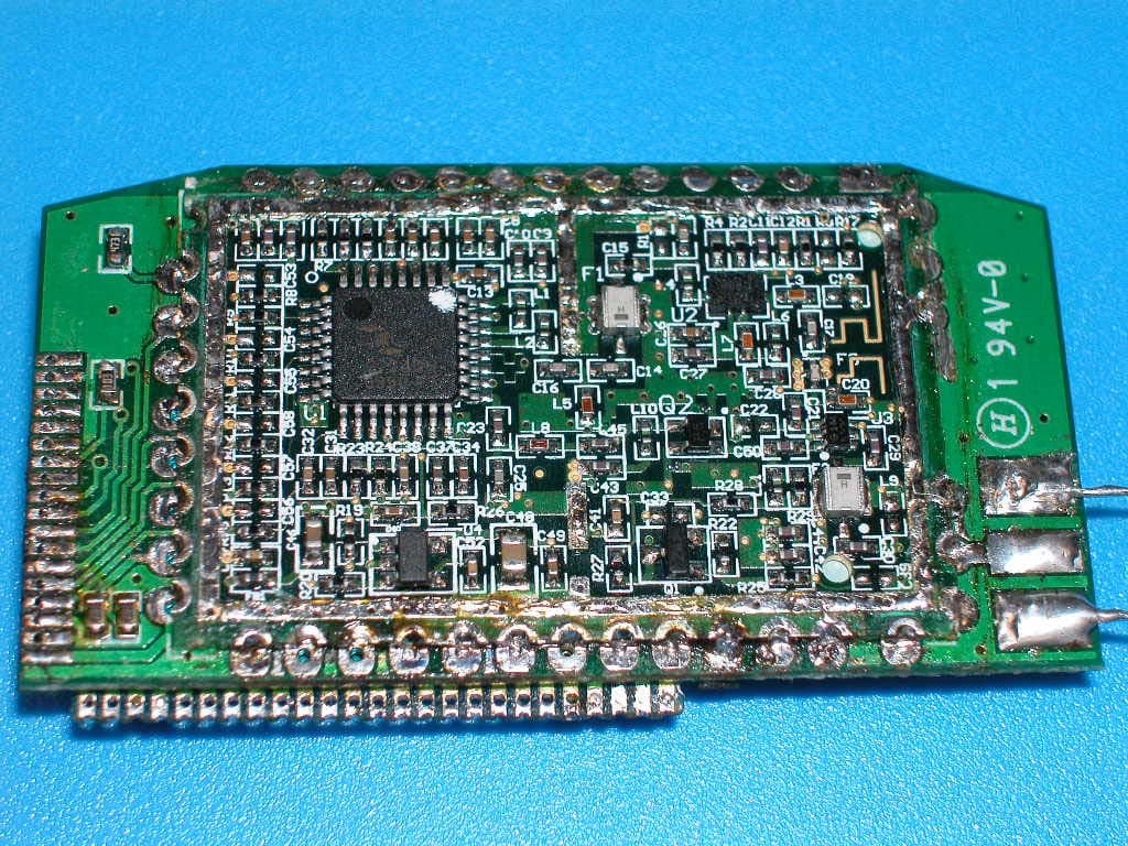
S92IB368TXV1
Sep 08, 2005iBall (Transmitter Dock Unit)
Equipment Class
DSS - Part 15 Spread Spectrum Transmitter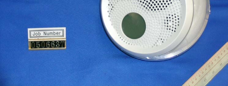
S92WRS368RXV1
Jul 07, 2005Music Sphere - Wireless Remote Speaker
Equipment Class
DSS - Part 15 Spread Spectrum Transmitter