SA4-OPTITIRETire Pressure Monitoring System
WABCO GmbH
Click to zoom
Application Details
- Equipment Class
- DSC - Part 15 Security/Remote Control Transmitter
- Date of Grant
- Dec 01, 2015
- Application Purpose
- Original Equipment
- Date of Application
- Dec 01, 2015
- Equipment Note
- Tire Pressure Monitoring System
- Frequency Range
- 433.92000000 - 433.92000000
- Company
- WABCO GmbH
- Country
- Germany
Documents & Files
Document Text
Text extracted from the exhibit documents filed with the FCC. Open a document above to read the original.
Users Manual
OptiTire Tire Pressure Monitoring for Commercial Vehicles OptiTire Tire Pressure Monitoring for Commercial Vehicles System Description Edition 7 This publication is not subject to any update service. You will find the current version at http://www.wabco.info/xxxxxxxxxx © 2013/2015 WABCO Europe BVBA – All rights reserved. The right of amendment is reserved. Draft Version 1.2015(en) Xxx xxx xxx x OPTITIRE Table of Contents 4 1 Important instructions ............................................................................................................ 6 1.1 Information and Disclaimer ........................................................................................... 6 1.2 Symbols used ............................................................................................................... 6 1.3 General information ...................................................................................................... 7 1.4 General safety instructions ........................................................................................... 7 2 Introduction ............................................................................................................................. 8 2.1 OPTITIRE prevents tire blow-outs ................................................................................ 8 2.2 OPTITIRE reduces cost ............................................................................................... 8 3 System Description .............................................................................................................. 10 3.1 OPTITIRE Basic Functions ........................................................................................ 10 3.2 OPTITIRE at trailer-towing operation ......................................................................... 11 3.3 Configuration for bus and towing vehicle ................................................................... 11 3.4 Configuration for trailers ............................................................................................. 13 3.5 Certificates .................................................................................................................. 16 4 Components .......................................................................................................................... 18 4.1 Wheel module WM2 ................................................................................................... 18 4.2 Wheel Internal Sensor (WIS) ...................................................................................... 21 4.3 Electronic Control Unit (ECU) ..................................................................................... 22 4.4 The display ................................................................................................................. 23 4.5 Connecting cable ........................................................................................................ 24 4.6 Connecting tube ......................................................................................................... 27 5 Operation ............................................................................................................................... 28 5.1 Warning signals .......................................................................................................... 28 5.2 Switch on of ignition.................................................................................................... 28 5.3 Checking pressure values .......................................................................................... 29 5.4 Display of faults .......................................................................................................... 30 5.5 Adjusting tire pressures .............................................................................................. 31 5.6 Display of System Errors ............................................................................................ 31 5.7 Operation via SmartBoard .......................................................................................... 33 6 Installation ............................................................................................................................. 34 6.1 Mounting the wheel modules – WM2 ......................................................................... 35 6.2 Mounting the wheel modules – WIS ........................................................................... 37 9.3 Mounting the ECU in bus / towing vehicle .................................................................. 39 6.3 Wiring in towing vehicle/bus ....................................................................................... 40 6.4 Mounting the ECU in the trailer .................................................................................. 41 6.5 Wiring in trailer ............................................................................................................ 41 6.6 Start-up ....................................................................................................................... 42 7 Workshop instructions ......................................................................................................... 44 7.1 Diagnosis .................................................................................................................... 45 7.2 Wheel Changes .......................................................................................................... 46 7.3 Replacing PA tubes .................................................................................................... 47 7.4 Replacing hose connections ...................................................................................... 47 7.5 Replacing wheel module I with wheel module II ........................................................ 48 7.6 Creeping pressure loss ......................................................................…
Text truncated - open the document above for the full version.
Cover Letter(s)
Long/Short-term Confidentiality Request PHOENIX TESTLAB GmbH Date: 22 July 2015 Product Certification Königswinkel 10 D 32825 Blomberg FCC ID: SA4-OPTITIRE To Whom it may concerns, Pursuant to sections 0.457(d) and 0.459 of CFR 47 and to avoid premature release of sensitive information prior to marketing or release of the product to the public, we hereby requests long-term confidential treatment of information accompanying this application as outlined below: Schematics Parts List Block Diagram Tune-Up Info Operational Description In addition we hereby request the following exhibits contained in this application to be temporarily (short-term confidentilality) withheld from the public disclosure for an initial period of days until: not applicable External Photos Test Setup Photos Internal Photos Users Manual The above materials contain trade secrets and proprietary information not customarily released to the public. The public disclosure of these matters might be harmful to the applicant and provide unjustified benefits to its competitors. The applicant understands that pursuant to rule 0.457(d), disclosure of this application and all accompanying documentation will not be made before the date of the GRANT for this application. Signatory Anton Stang Graduated Certification Specialist PHOENIX TESTLAB GmbH
External Photos
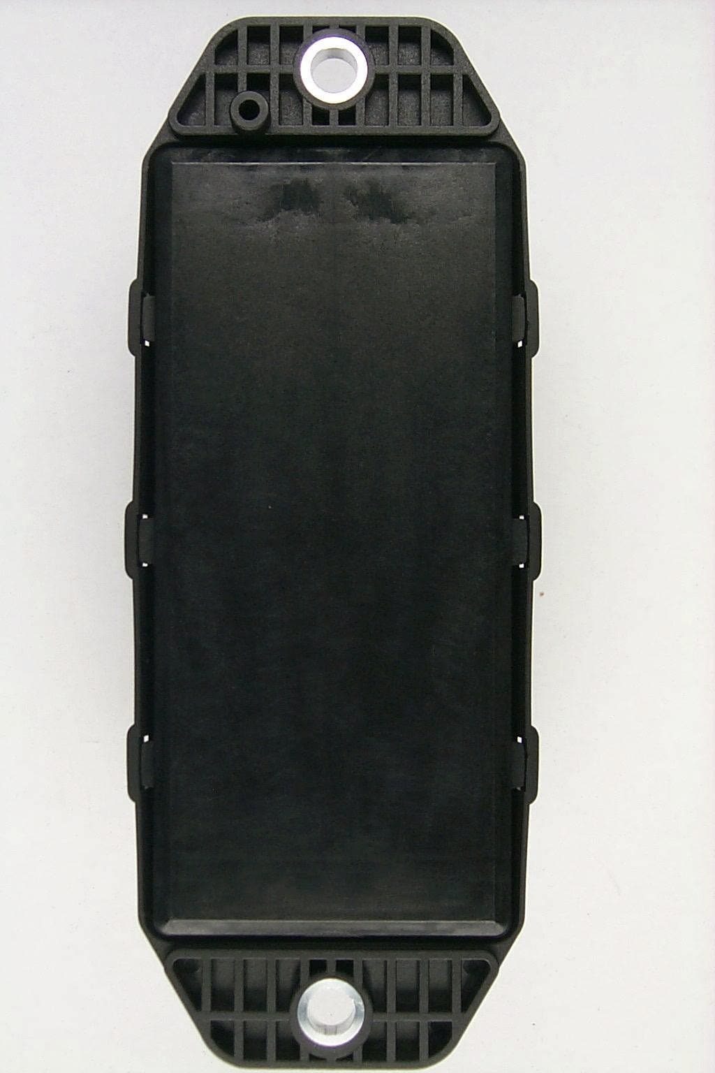
Annex B: External photographs Test engineer: Thomas KÜHN Report Number: F150998E3 Date of issue: 15 April 2015 Order Number: 15-110998 page 1 of 4 150998_7.JPG: OptiTire ECU, 3-D-view 1 Annex B: External photographs Test engineer: Thomas KÜHN Report Number: F150998E3 Date of issue: 15 April 2015 Order Number: 15-110998 page 2 of 4 150998_5.JPG: OptiTire ECU, 3-D-view 2 Annex B: External photographs Test engineer: Thomas KÜHN Report Number: F150998E3 Date of issue: 15 April 2015 Order Number: 15-110998 page 3 of 4 150998_6.JPG: OptiTire ECU, type plate view Annex B: External photographs Test engineer: Thomas KÜHN Report Number: F150998E3 Date of issue: 15 April 2015 Order Number: 15-110998 page 4 of 4 150998_1.JPG: OptiTire ECU, top view
ID Label/Location Info
Lable Location Info
Internal Photos
Annex C: Internal photographs Test engineer: Thomas KÜHN Report Number: F150998E3 Date of issue: 15 April 2015 Order Number: 15-110998 page 1 of 3 150998_10.JPG: OptiTire ECU, internal view Annex C: Internal photographs Test engineer: Thomas KÜHN Report Number: F150998E3 Date of issue: 15 April 2015 Order Number: 15-110998 page 2 of 3 150998_3.JPG: OptiTire ECU, PCB, top view Annex C: Internal photographs Test engineer: Thomas KÜHN Report Number: F150998E3 Date of issue: 15 April 2015 Order Number: 15-110998 page 3 of 3 150998_4.JPG: OptiTire ECU, PCB, bottom view
Test Report
Königswinkel 10 32825 Blomberg Germany Phone: +49 (0) 52 35 95 00-0 Fax: +49 (0) 52 35 95 00-10 Test Report Report Number: F150998E3 Applicant: WABCO Fahrzeugsysteme GmbH Manufacturer: WABCO Fahrzeugsysteme GmbH Equipment under Test (EUT): OptiTire ECU Laboratory accredited by Deutsche Akkreditierungsstelle (DAkkS) GmbH in compliance with DIN EN ISO/IEC 17025 Test engineer: Thomas KÜHN Report Number: F150998E3 Date of issue: 15 April 2015 Order Number: 15-110998 page 2 of 35 REFERENCES [1] ANSI C63.10-2013 American National Standard of Procedures for Compliance Testing of Unlicensed Wireless Devices. [2] FCC CFR 47 Part 15 Radio Frequency Devices [3] RSS-210 Issue 8 (December 2010) Licence-exempt Radio Apparatus (All Frequency Bands): Category I Equipment [4] RSS-Gen Issue 4 (November 2014) General Requirements for Compliance of Radio Apparatus [6] Publication Number 913591 (March 2007) Measurement of radiated emissions at the edge of the band for a Part 15 RF Device TEST RESULT The requirements of the tests performed as shown in the overview (clause 4) were fulfilled by the equipment under test. The complete test results are presented in the following. RESERVATION This test report is only valid in its original form. Any reproduction of its contents in extracts without written permission of the accredited test laboratory PHOENIX TESTLAB GmbH is prohibited. The test results herein refer only to the tested sample. PHOENIX TESTLAB GmbH is not responsible for any generalizations or conclusions drawn from these test results concerning further samples. Any modification of the tested samples is prohibited and leads to the invalidity of this test report. Each page necessarily contains the PHOENIX TESTLAB Logo and the TEST REPORT NUMBER. Test engineer: Thomas KÜHN 15 April 2015 Name Signature Date Authorized reviewer: Bernd STEINER 15 April 2015 Name Signature Date Test engineer: Thomas KÜHN Report Number: F150998E3 Date of issue: 15 April 2015 Order Number: 15-110998 page 3 of 35 Contents: Page 1 Identification ............................................................................................................................................. 4 1.1 Applicant ............................................................................................................................................. 4 1.2 Manufacturer ....................................................................................................................................... 4 1.3 Test laboratory .................................................................................................................................... 4 1.4 EUT (Equipment Under Test) ............................................................................................................. 5 1.5 Technical data of equipment ............................................................................................................... 5 1.6 Dates ................................................................................................................................................... 5 2 Operational states .................................................................................................................................... 6 3 Additional information ............................................................................................................................... 7 4 Overview .................................................................................................................................................. 7 5 Test results ............................................................................................................................................... 8 5.1 Average correction factor .................................................................................................................... 8 5.2 Bandwidth ......................................................................................................................................... 14 5.2.1 Method of measurement (20 dB bandwidth) .......................................................................... 14 5.2.2 Method of measurement (99 % bandwidth) ............................................................................ 14 5.2.3 Test results (20 dB bandwidth) ............................................................................................... 15 5.2.4 Test results (99 % bandwidth) ................................................................................................ 16 5.3 Band-edge compliance ..................................................................................................................... 17 5.3.1 Method of measurement (Band-edge compliance (radiated)) ................................................ 17 5.3.2 Test results (Band-edge compliance (radiated)) .................................................................... 18 5.4 Transmission time control ................................................................................................................. 19 5.4.1 Method of measurement (transmission time control) ............................................................. 19 5.4.2 Test results (transmission time control) .................................................................................. 20 5.5 Radiated emissions ........................................................................................................................... 22 5.5.1 Method of measurement (Radiated emissions) ...................................................................... 22 5.5.2 Test results (radiated emissions) ............................................................................................ 29 5.5.2.1 Preliminary radiated emission measurement (150 kHz to 5 GHz) .................................... 29 5.5.2.2 Final radiated emission measurement (30 MHz to 1 GHz) ............................................... 32 5.5.2.3 Final radiated emi…
Text truncated - open the document above for the full version.
Test Setup Photos
Annex A: Test setup photographs Test engineer: Thomas KÜHN Report Number: F150998E3 Date of issue: 15 April 2015 Order Number: 15-110998 page 1 of 7 150998_e.JPG: OptiTire ECU, test set-up fully anechoic chamber, pos. 1 Annex A: Test setup photographs Test engineer: Thomas KÜHN Report Number: F150998E3 Date of issue: 15 April 2015 Order Number: 15-110998 page 2 of 7 150998_a.JPG: OptiTire ECU, test set-up fully anechoic chamber, pos. 2 Annex A: Test setup photographs Test engineer: Thomas KÜHN Report Number: F150998E3 Date of issue: 15 April 2015 Order Number: 15-110998 page 3 of 7 150998_h.JPG: OptiTire ECU, test set-up fully anechoic chamber Annex A: Test setup photographs Test engineer: Thomas KÜHN Report Number: F150998E3 Date of issue: 15 April 2015 Order Number: 15-110998 page 4 of 7 150998_d.JPG: OptiTire ECU, test set-up fully anechoic chamber Annex A: Test setup photographs Test engineer: Thomas KÜHN Report Number: F150998E3 Date of issue: 15 April 2015 Order Number: 15-110998 page 5 of 7 150998_g.JPG: OptiTire ECU, test set-up fully anechoic chamber Annex A: Test setup photographs Test engineer: Thomas KÜHN Report Number: F150998E3 Date of issue: 15 April 2015 Order Number: 15-110998 page 6 of 7 150998_i.JPG: OptiTire ECU, test set-up open area test site, pos. 1 Annex A: Test setup photographs Test engineer: Thomas KÜHN Report Number: F150998E3 Date of issue: 15 April 2015 Order Number: 15-110998 page 7 of 7 150998_j.JPG: OptiTire ECU, test set-up open area test site, pos. 2
Contact Information
Applicant
Ulfert Ulken
Test Firm
PHOENIX TESTLAB GmbHHolger Bentje
Technical Specifications
| # | Rule Parts | Frequency Range | Power Output |
|---|---|---|---|
| 1 | 15.231 | 433.92 MHz - 433.92 MHz | - |
Other Applications from WABCO GmbH
SA4-ECU220
Sep 23, 2004IVTM Electronic Control Unit
Equipment Class
DSR - Part 15 Remote Control/Security Device Transceiver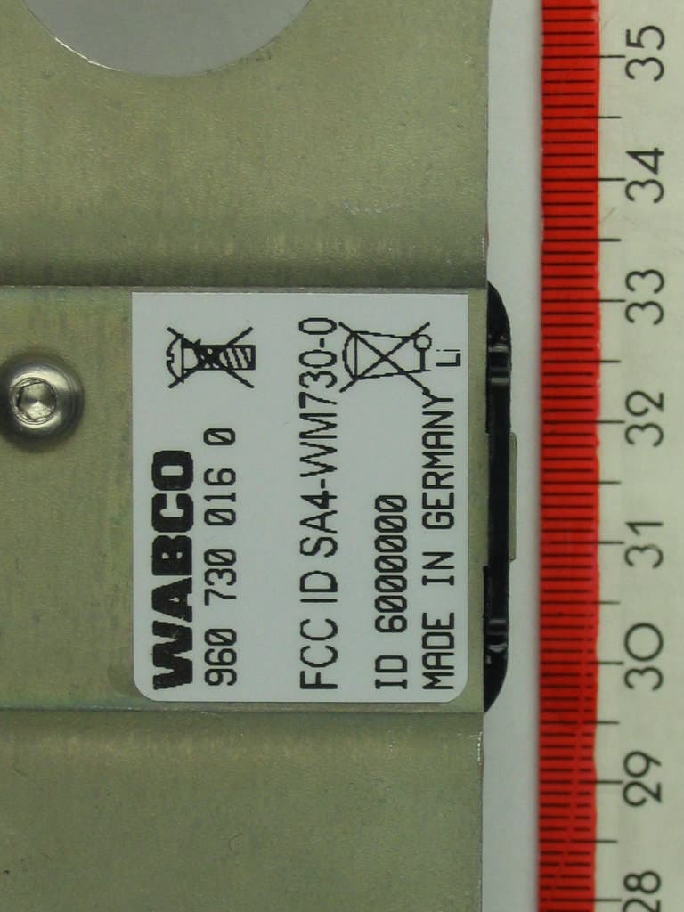
SA4-WM730-0
Sep 23, 2004Integrated Vehicle Tire Monitoring Wheel Module
Equipment Class
DSC - Part 15 Security/Remote Control Transmitter