SAGH3Bar Code Scanner and RFID Reader
JADAK, a business unit of Novanta Corporation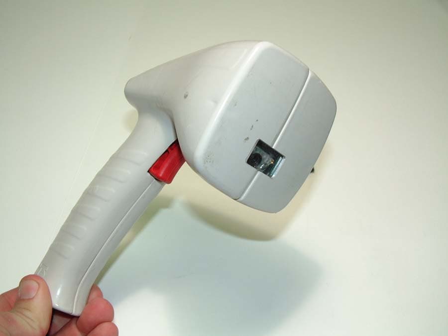
Click to zoom
Application Details
- Equipment Class
- DXT - Part 15 Low Power Transceiver, Rx Verified
- Date of Grant
- Aug 23, 2005
- Application Purpose
- Original Equipment
- Date of Application
- Aug 23, 2005
- Equipment Note
- Bar Code Scanner and RFID Reader
- Frequency Range
- 13.56000000 - 13.56000000
- Country
- United States
Documents & Files
Document Text
Text extracted from the exhibit documents filed with the FCC. Open a document above to read the original.
Users Manual
Part No. RF-109-0405 DR1000 TM Dual Reader User Manual ©2005 Precision Dynamics Corporation DR1000 User Manual Precision Dynamics Corp. Page 2 of 44 TABLE OF CONTENTS SAFETY PRECAUTIONS & IMPORTANT SAFETY INSTRUCTIONS.............................. 5 1 PURPOSE OF THIS DOCUMENT........................................................................................... 8 2 PRODUCT OVERVIEW............................................................................................................... 9 2.1 GENERAL DESCRIPTION.................................................................................................................... 9 2.2 FEATURES......................................................................................................................................... 9 2.3 DR1000 RFID TAG COMPATIBILITY............................................................................................... 10 2.4 DR1000 BARCODE COMPATIBILITY................................................................................................. 10 3 MODELS AND MODES OF OPERATION........................................................................... 11 3.1 COMMAND MODE........................................................................................................................... 11 3.2 TRIGGER MODE.............................................................................................................................. 12 3.2.1 Scan Sequence................................................................................................................ 12 3.2.2 Barcode Data Style........................................................................................................ 13 3.2.3 RFID Data Style.............................................................................................................. 13 3.2.4 Keyboard Emulation (Wedge)................................................................................... 14 3.3 SCANNING AN RFID TAG............................................................................................................... 14 3.4 SCANNING A BARCODE................................................................................................................... 14 3.5 FIELD INTERPRETATION................................................................................................................. 14 3.5.1 Overview........................................................................................................................... 14 3.5.2 Field Interpretation Arrays......................................................................................... 15 3.5.3 Keyboard emulation and serial differences.......................................................... 16 3.5.4 Error Conditions and Handling.................................................................................. 16 4 POWER AND HOST INTERFACE CONNECTIONS....................................................... 18 4.1 POWER............................................................................................................................................ 18 4.2 USB................................................................................................................................................ 18 4.3 RS-232............................................................................................................................................ 19 4.4 PS/2................................................................................................................................................ 21 5 USER INTERFACES................................................................................................................... 23 5.1 LEDS.............................................................................................................................................. 23 5.2 BEEPER........................................................................................................................................... 23 5.3 TRIGGER......................................................................................................................................... 23 6 FIRMWARE UPGRADES.......................................................................................................... 24 APPENDIX 1 - BaRS SOFTWARE................................................................................................. 25 INSTALLING BARS.................................................................................................................................... 25 INSTALLING USB SERIAL COMMUNICATION DRIVERS.............................................................................. 25 STARTING THE BARS APPLICATION.......................................................................................................... 27 MAIN TOOL BAR....................................................................................................................................... 27 APPLICATION CONFIGURATION................................................................................................................ 31 Serial Port....................................................................................................................................... 31 Baud Rate........................................................................................................................................ 32 Barcode Scan Timeout............................................................................................................... 32 SCANNER SETTINGS.................................................................................................................................. 32 Baud Rate........................................................................................................................................ 32 USB Mode......................................................................................…
Text truncated - open the document above for the full version.
Cover Letter(s)
American Telecommunications Certification Body Inc. 6731 Whittier Ave, McLean, VA 22101 July 29, 2005 RE: Skyetek, Inc. FCC ID: SAGH3 ATCB#: ATCB I have a few comments on this Application. 1. The Block Diagram is not consistent with the requirements of 2.1033(b)(5). Please review. CFR 2.1033(b) (5) A block diagram showing the frequency of all oscillators in the device. The signal path and frequency shall be indicated at each block. The tuning range(s) and intermediate frequency ( ies) shall be indicated at each block. A schematic diagram is also required for intentional radiators. 2. In the future you need to list the FRN on the Form 731 or it will be sent back to the lab for revision. 3. Please be aware the photos cannot be declared confidential unless the equipment is a scanning receiver. 4. Please submit files as pdf so they are converted by the testing lab rather than the FCC. It will help with file size and keep the correct file in the correct place. 5. Please upload label location photos as required by the FCC. 6. Please upload test setup photos as required by the FCC. As a rule test setup photos are required for all Part 15 devices. Thank you, Douglas E. Noble Examining Engineer mailto: [email protected] The items indicated above must be submitted before processing can continue on the above referenced application. Failure to provide the requested information may result in application termination. Correspondence should be considered part of the permanent submission and may be viewed from the Internet after a Grant of Equipment Authorization is issued. z Page 2 July 29, 2005 Please do not respond to this correspondence using the email reply button. In order for your response to be processed expeditiously, you must submit your documents through the AmericanTCB.com website. Also, please note that partial responses increase processing time and should not be submitted. Any questions about the content of this correspondence should be directed to the sender.
External Photos
External Photos
Test Report
M. Flom Associates, Inc. 3356 N. San Marcos Place, Suite 107 Chandler, Arizona 85225-7176 FCC ID: SAGH3 (480) 926-3100 phone, fax (480) 926-3598 MFA p0540008, d0540030 Date of Report: Date of Submission: May 14, 2005 July 27, 2005 Federal Communications Commission Via: Electronic Filing Attention: Authorization & Evaluation Division Applicant: SkyeTek, Inc. Equipment: DR1000 FCC ID: SAGH3 FCC Rules: 15.225 Gentlemen: On behalf of the Applicant, enclosed please find Application Form 731, Engineering Test Report and all pertinent documentation, the whole for approval of the referenced equipment as shown. Filing fees are attached. We trust the same is in order. Should you need any further information, kindly contact the writer who is authorized to act as agent. Sincerely yours, Michael Schafer, President enclosure(s) cc: Applicant MS/del M. Flom Associates, Inc. 3356 N. San Marcos Place, Suite 107 Chandler, Arizona 85225-7176 FCC ID: SAGH3 (480) 926-3100 phone, fax (480) 926-3598 MFA p0540008, d0540030 Transmitter Certification of Model: DR1000 FCC ID: SAGH3 to Federal Communications Commission Rule Part(s) 15.225 Date of Report: Date of Submission: May 14, 2005 July 27, 2005 On the Behalf of the Applicant: SkyeTek, Inc. At the Request of: P.O. 2005-N166 SkyeTek, Inc. 2845 Wilderness Place Boulder, CO 80301 Attention of: Tom DiGennero (303)615-8090 E-mail: [email protected] Compiled by: Michael Findley, Laboratory Manager M. Flom Associates, Inc. 3356 N. San Marcos Place, Suite 107 Chandler, Arizona 85225-7176 FCC ID: SAGH3 (480) 926-3100 phone, fax (480) 926-3598 MFA p0540008, d0540030 The Applicant has been cautioned as to the following: 15.21 Information to the User. The users manual or instruction manual for an intentional radiator shall caution the user that changes or modifications not expressly approved by the party responsible for compliance could void the user's authority to operate the equipment. 15.27(a) Special Accessories. Equipment marketed to a consumer must be capable of complying with the necessary regulations in the configuration in which the equipment is marketed. Where special accessories, such as shielded cables and/or special connectors are required to enable an unintentional or intentional radiator to comply with the emission limits in this part, the equipment must be marketed with, i.e. shipped and sold with, those special accessories. However, in lieu of shipping or packaging the special accessories with the unintentional or intentional radiator, the responsible party may employ other methods of ensuring that the special accessories are provided to the consumer, without additional charge. Information detailing any alternative method used to supply the special accessories for a grant of equipment authorization or retained in the verification records, as appropriate. The party responsible for the equipment, as detailed in § 2.909 of this chapter, shall ensure that these special accessories are provided with the equipment. The instruction manual for such devices shall include appropriate instructions on the first page of text concerned with the installation of the device that these special accessories must be used with the device. It is the responsibility of the user to use the needed special accessories supplied with the equipment. M. Flom Associates, Inc. 3356 N. San Marcos Place, Suite 107 Chandler, Arizona 85225-7176 FCC ID: SAGH3 (480) 926-3100 phone, fax (480) 926-3598 MFA p0540008, d0540030 Table of Contents Rule Description Page . Standard Test Conditions and Engineering Practices 2 2.1033(c) General Information Required 4 2.1046(a) RF Power Output (Radiated) 5 2.1049(c)(1) Emission Masks (Occupied Bandwidth) 6 2.1055(a)(1) Frequency Stability (Temperature Variation) 11 2.1055(b)(1) Frequency Stability (Voltage Variation) 13 2.202(g) Necessary Bandwidth and Emission Bandwidth 15 M. Flom Associates, Inc. 3356 North San Marcos Place, Suite 107 Page 1 of 15 Chandler, Arizona 85225-7176 FCC ID: SAGH3 (480) 926-3100 phone, fax (480) 926-3598 MFA p0540008, d0540030 Required information per ISO/IEC Guide 25-1990, paragraph 13.2: a) Test Report b) Laboratory: (FCC: 31040/SIT) (Canada: IC 2044) M. Flom Associates, Inc. 3356 N. San Marcos Place, Suite 107 Chandler, AZ 85225 c) Report Number: d0540030 d) Client: SkyeTek, Inc. 2845 Wilderness Place Boulder, CO 80301 e) Identification: DR1000 FCC ID: SAGH3 EUT Description: Bar Code Scanner and RFID Reader f) EUT Condition: Not required unless specified in individual tests. g) Report Date: May 16, 2005 EUT Received: April 21, 2005 h, j, k): As indicated in individual tests. i) Sampling method: No sampling procedure used. l) Uncertainty: In accordance with MFA internal quality manual. m) Supervised by: Michael Findley, Laboratory Manager n) Results: The results presented in this report relate only to the item tested. o) Reproduction: This report must not be reproduced, except in full, without written permission from this laboratory. Accessories: Qty Type Make, Model S/N FCC ID 1 PSU PS1-5 (Generic 5V, 500mA) None None Cables: Qty Type Length, m Shield Shielded Hood Ferrite 1 USB 2.0 No No No 1 RS-232 (+Ext Power) 2.0 No No No 1 PS-2 2.0 No No No M. Flom Associates, Inc. 3356 North San Marcos Place, Suite 107 Page 2 of 15 Chandler, Arizona 85225-7176 FCC ID: SAGH3 (480) 926-3100 phone, fax (480) 926-3598 MFA p0540008, d0540030 Standard Test Conditions and Engineering Practices Except as noted herein, the following conditions and procedures were observed during the testing: In accordance with ANSI C63.4-1992/2000, section 6.1.9, and unless otherwise indicated in the specific measurement results, the ambient temperature of the actual EUT was maintained within the range of 10° to 40°C (50° to 104 °F) unless the particular equipment requirements specify testing over a different temperature range. Also, unless otherwise indicated, the humidity levels were in the range of 10% to 90% relative humidity. Prior to testing, the E…
Text truncated - open the document above for the full version.
Test Setup Photos
Test Setup Photos: Radiated Emissions State: State: Test Setup: A/C Powerline Conducted Emissions
Contact Information
Applicant
Eva Gravius(VP Engineering)
Technical Contact
M. Flom Associates, Inc.David Lee
[email protected]480-926-3100
3356 N. San Marcos Place, Suite 107 · Chandler, Arizona · United States
Test Firm
Compliance Testing, LLCMichael Schafer
Technical Specifications
| # | Rule Parts | Frequency Range | Power Output |
|---|---|---|---|
| 1 | 15C | 13.56 MHz - 13.56 MHz | - |