SAJSKB13EAPSelf-Ballasted Lamp
Toshiba Lighting & Technology Corporation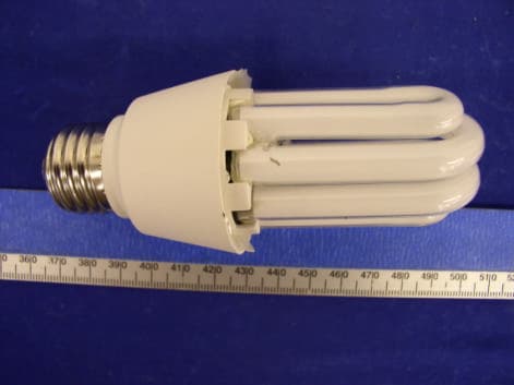
Click to zoom
Application Details
- Equipment Class
- 8CC - Part 18 Consumer Device
- Date of Grant
- Aug 03, 2004
- Application Purpose
- Original Equipment
- Date of Application
- Aug 03, 2004
- Equipment Note
- Self-Ballasted Lamp
- Frequency Range
- 0.04000000 - 0.05000000
- Country
- Japan
Documents & Files
Document Text
Text extracted from the exhibit documents filed with the FCC. Open a document above to read the original.
Users Manual
User manual Operating Instructions: ·Replaces ordinary incandescent lamp. ·Use on 120V 50/60/Hz circuits. ·Keep away from the flammables. ·Turn the power off before installation, removal, and cleaning. Cautions for Use: ·Not for use where directly exposed to water . ·Do not use with dimmers,timers or other control devices. ·Not for use in totally enclosed recessed fixtures. WARNING 1. This device complies with Part 18 of the FCC Rules. 2. This product may cause interference to TV or other household equipment ,and if these case occur ,please move them far away from it. ·This product interference when used near 0.7V, radio,wireless remote control or maritime safety communication equipment,or other critical navigation of communication equipment operating between 0.45----30MHZ. If inteference would occur ,move the lamp away from the appliance a distance of there feet or more ,Or plug the lamp or the appliance into a different outlet. ·This product complies with Part 18 of the FCC Rules but may cause interference to radios, television,wireless telephones,and remote controls. If interference occurs, move product away from the device or plug either into a different outlet, or move the lamp out of the sight with the remote control receiver. Block Diagram circuit description: When a power of 120V/50-60Hz is inputted into the ballast,it goes through D1,D2 and C2,C3 to be rectified ,filtrated and converted into a direct current power .Then the later goes through R1 and R2 to charge C4. As soon as the voltage of C4 is up to 32±2V. Q2 is actuated. On the actuation of Q2, operating power is goes through C6, C7 ,L2, L3, Q2, R6 to light the fluorescent lamp tube .The operating power is maintains a stable working status via the two oscillation coils of C6, L3, Q2 and L3, C6, Q1(Operating frequency:40-50KHz) AC Input RFI Filter Commute Filter ????? Lamp Load
External Photos
APPENDIX C - EUT PHOTOGRAPHS Chassis – Front View Chassis – Side View Chassis – Cover Off View
ID Label/Location Info
APPENDIX A - FCC PRODUCT LABELING AND WARNING STATEMENT Proposed Label Location on EUT EUT- Side View / FCC Label Location FCC Warning Statement This device complies with Part 18 of FCC rules. Information on the following matters shall be provided to the user in the instruction manual or on the packaging if an instruction manual is not provided for any type of any ISM equipment: a. The interference potential of the device or system b. Maintenance of the system c. Simple measures that can be taken by the user to correct interference.
Internal Photos
EUT – Component View EUT – Solder View
Test Report
Note: The test report is specially limited to the use of the above client company and the product model. It may not be duplicated without prior written consent of Bay Area Compliance Laboratory Corporation. This report must not be used by the client to claim product certification, approval, or endorsement by NVLAP, NIST or any agency of the U.S. Government FCC PART 18 MEASUREMENT AND TEST REPORT FOR Toshiba Lighting & Technology Corporatin 2-13, MINAMISHINAGAWA 2-CHOME. SHINAGAWA-KU.TOKYO 1408660 FCC ID: SAJSKB13EAP 2004-06-22 This Report Concerns: Original Report Equipment Type: Self-ballasted lamp Test Engineer: Jerry Wang/ Report Number: R0406153 Test Date: 2004-06-15 Reviewed By: Ling Zhang/ Prepared By: Bay Area Compliance Laboratory Corporation 230 Commercial Street Sunnyvale, CA 94085 Tel: (408) 732-9162 Fax: (408) 732-9164 Toshiba Lighting & Technology Corporation FCC ID: SAJSKB13EAP Report #R0406153 Page 2 of 9 FCC Part 18 ID Test Report TABLE OF CONTENTS 1 - GENERAL INFORMATION.................................................................................................................................................3 1.1 PRODUCT DESCRIPTION FOR EQUIPMENT UNDER TEST (EUT)........................................................................................3 1.2 OBJECTIVE................................................................................................................................................................................3 1.3 RELATED SUBMITTAL(S)/GRANT(S).....................................................................................................................................3 1.4 TEST METHODOLOGY..............................................................................................................................................................3 1.5 TEST FACILITY.........................................................................................................................................................................3 2 - SYSTEM TEST CONFIGURATION..................................................................................................................................4 2.1 JUSTIFICATION..........................................................................................................................................................................4 2.2 EUT EXERCISE PROGRAM......................................................................................................................................................4 2.3 SCHEMATICS/BLOCK DIAGRAM.............................................................................................................................................4 2.4 EQUIPMENT MODIFICATIONS.................................................................................................................................................4 2.5 LOCAL SUPPORT EQUIPMENT.................................................................................................................................................4 2.6 INTERFACE PORTS AND CABLING..........................................................................................................................................4 2.7 CONFIGURATION OF TEST SYSTEM.......................................................................................................................................5 2.8 TEST SETUP BLOCK DIAGRAM...............................................................................................................................................5 3 - CONDUCTED EMISSIONS TEST DATA........................................................................................................................6 3.1 MEASUREMENT UNCERTAINTY.............................................................................................................................................6 3.2 EUT SETUP...............................................................................................................................................................................6 3.3 EMI RECEIVER SETUP............................................................................................................................................................6 3.4 EQUIPMENT LIST AND DETAILS.............................................................................................................................................6 3.5 TEST PROCEDURE....................................................................................................................................................................6 3.6 SUMMARY OF TEST RESULTS.................................................................................................................................................7 3.7 CONDUCTED EMISSIONS TEST DATA....................................................................................................................................7 Toshiba Lighting & Technology Corporation FCC ID: SAJSKB13EAP Report #R0406153 Page 3 of 9 FCC Part 18 ID Test Report 1 - GENERAL INFORMATION 1.1 Product Description for Equipment Under Test (EUT) The Toshiba Lighting & Technology Corporation’s product, Model: SKB 13EAP or the "EUT" as referred to in this report is a Self-ballasted lamp, which measures 4”L x 2.5”W x 2.5”H. *The test data gathered are from production sample, serial number:TL06153, provided by the manufacturer. 1.2 Objective This Following test report is prepared on behalf of Toshiba Lighting & Technology Corporation in accordance with Part 2, Subpart J, and Part 18, Subparts A and B of the Federal Communication Commissions rules. The objective is to determine compliance with FCC Part 18 limit requirements for Industrial, Scientific, and Medical Equipment. 1.3 Related Submittal(s)/Grant(s) No Related Submittals. 1.4 Test Methodology All measurements contained in this report were conducted in accordance with MP-5, FCC Methods of Measurements of Radio…
Text truncated - open the document above for the full version.
Test Setup Photos
APPENDIX B - TEST SETUP PHOTOGRAPHS Conducted Emission – Front View Conducted Emission – Side View
Contact Information
Applicant
Makoto Nakao(Marketing Manager)
Test Firm
Bay Area Compliance Laboratory Corp.John Chan
Technical Specifications
| # | Rule Parts | Frequency Range | Power Output |
|---|---|---|---|
| 1 | 18 | 0.04 MHz - 0.05 MHz | - |
Other Applications from Toshiba Lighting & Technology Corporation
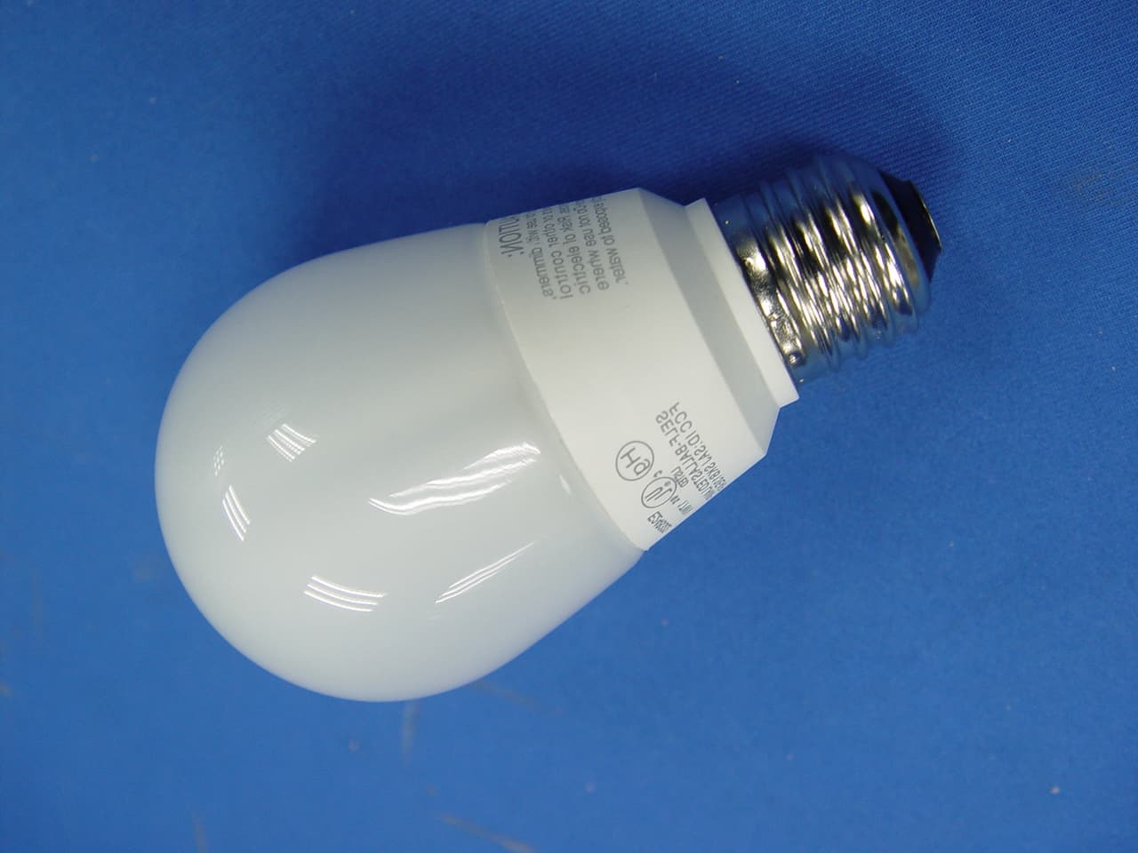
SAJEFA13J
Mar 26, 2006Self Ballasted Lamp
Equipment Class
8CC - Part 18 Consumer Device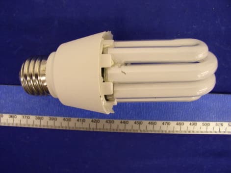
SAJSKB13WAP
Jul 13, 2004Self Ballasted Lamp
Equipment Class
8CC - Part 18 Consumer Device